 FREE 1 to 3-Day Delivery on Orders $149+ Details
How to Install Addictive Desert Designs Rear Frame Gusset & Bump Stop Kit (09-14 All) on your Ford F-150
Installation Time
3 hours
Tools Required
- 90’ drill
- ½” drill bit
- ¾” wrench
- ¾” – ½” drive socket and ratchet or impact gun
- 13MM socket and ratchet
- 1-1/4 wrench (for the top bolt on the bump stop)
PREPARATION STEPS
1. Disconnect the negative terminal on the battery. With the vehicle on level ground and the emergency brake set, block the front tires.
2. Jack up the rear of the vehicle and support the frame rails with jack stands. Never work under an unsupported vehicle!
3. Remove the rear tires.
4. Remove the spare tire.
5. You do not need to remove the bed for this installation, but it will make the installation much easier.
6. You will need the following tools:
a. 90’ drill
b. ½” drill bit
c. ¾” wrench
d. ¾” – ½” drive socket and ratchet or impact gun
e. 13MM socket and ratchet
f. 1-1/4 wrench (for the top bolt on the bump stop)
7. Hardware Included:
a. 6 – 4 ½” x ½” Grade 8 Bolts
b. 4 – 4” x ½” grade 8 Bolts
c. 6 – 1 ½” x ½” Grade 8 Bolts
d. 32 - ½” Grade 8 Washers
e. 16 – ½” Locknuts
f. 4 – 3/16” x 2” x 2” x ½” OD Square Washers
INSTALLATION INSTRUCTIONS
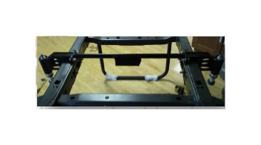
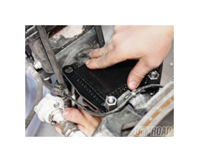
1. Remove factory stock bump stop and mount from the frame.
2. Locate the Bump Stop Assemblies, determine which are the driver and passenger sides. Use the hole from the factory bump stop and install bolt to hold the side frame gusset bracket to the frame. Make sure to tighten the factory 13mm bolt to ensure that the plate is mounted securely before moving to the next step. Do this on both sides of the truck
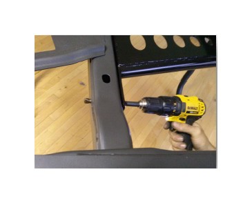
3. Using the Bump Stop Assemblies as a template, drill a ½” hole through the frame gusset and into the inside portion of the stock frame. Pay attention to drill as straight as possible.
**** Caution: Be careful not to drill into the factory hard brake lines on the inside of the framerail on the driver’s side of the truck.
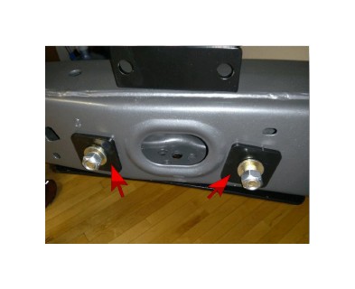
4. Use the 4½” x ½” Grade 8 Bolts to go through the bump stop bracket assembly, the side frame gusset plate, and through the stock frame. Place one ½” washer on the bolt and insert from the outside inward.
5. Locate the 3/16” thick square 2” x 2” plates. Place these plates on the bolt on the inside of the frame rail. Then place a standard ½” washer over the threaded end and start the nut on the bolt. ***Do not tighten these bolts yet. It will be tightened later.
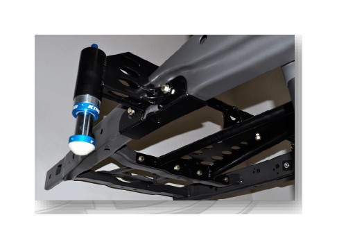
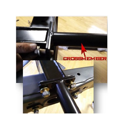
6. Locate the 1-1/2” tube cross member. Slide the tube up over the exhaust and on top of the frame rail. Line these plates up with the bump stop can assembly.
***The cross member mount in the center is tapered with the longer (bigger) side toward the Rear of the truck. This will line up with the under frame support.
7. Install 4 of the 1½” x ½” Grade 8 Bolts with washers through the cross member outer mounting plate to attach it to the bump stop mount assembly. Use washers and start the nuts. ****Do not tighten bolts yet.
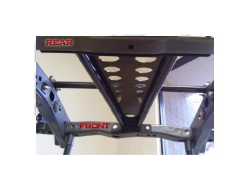
8. Locate the large triangular frame support assembly. Place the assembly under the truck with the wide end facing the rear. From under the frame place the assembly against the top plate of the cross member from step 7.
9. Locate the 1½” x ½” Grade 8 Bolts with washers to secure the triangular frame support to the cross member through the 2 holes. Make sure you put washers on the bolts on both sides and install the nut on the threaded end. Tighten these bolts now.
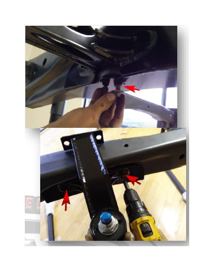
10. Next, locate the 2 holes in the front smaller side of the triangular frame support. Take the 90’ drill and ½” drill bit and drill through the frame assembly through both sides of the cross member. Install 4½” x ½” Grade 8 Bolts to secure the triangular frame support to the factory cross member. Make sure you use washers and put the nuts on the threaded end of the bolt. ****Do not tighten the bolts yet.
11. Locate the 4 holes in the rear larger side of the triangular frame support. Again, take the 90’ drill and ½” drill bit and drill through the stock cross member. Install 4½” x ½” Grade 8 Bolts to secure the triangular frame support to the stock cross member. Make sure you use washers and put the nuts on the threaded end of the bolt.
12. Now tighten all of the bolts mounting the triangular frame support to the cross members. You should have all 8 bolts mounting this assembly tight.
13. Locate the bump stop and remove the Schrader valve cap and mounting nut. Insert the bump stop into the outer bump stop mount assembly. Align the bump stop locating pin in the top cap of the mounting can. This will slide in and must be located before tightening the nut on the top mount.
****Make sure you align the pin before tightening the nut.
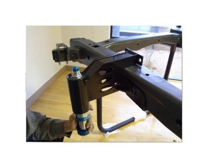
14. Tighten the top nut on both bump stops to ensure they are secure. Replace the Schrader valve cap.
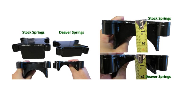
15. Check your bump stop pad assembly to make sure you have the correct size. If you have Deaver Springs, your pad assembly will be smaller than if you have stock springs. Refer to the pictures following this step for reference. Deaver Spring pad assemblies will be a little under 1/2” from the top of the pad assembly to the middle of the axle cutout. The stock spring pad assemblies will measure to about 1 1/4”. These measurements are not exact.
16. Locate the bump stop mount pad assembly and u-bolts. Set the bump stop pad on the top of the axle tube near the spring perch. Slide the u-bolt up from the bottom of the axle assembly through the mounting holes in the bump stop pad assembly. This will fit just between the shock mount and the spring perch on the axle. Make sure the bump stop pad is aligned on the axle to meet the bump stop when the suspension collapses. Follow step 17 for the correct alignment.
17. To ensure they are aligned correctly you must re-install the rear wheels and let the truck down off the jack stands to check for the alignment of the pads with the bump stops. The bump stop shaft should be 90 degrees to the pad when looking at the contact area where the bump stop will touch the bump stop pad on the rear axle. You should rotate the bump stop pad and u-bolts until they line up with the bump stop before tightening the nuts on the u-bolts. Once aligned, tighten the nuts on the u-bolts evenly by tightening them a little at a time and going in a clock wise rotation as you tighten.
***After tightening the nuts on the U-bolts, you must cut any excess threads off so that the U-bolt sits flush with the nut. Failure to do so may result in damage to your shock***
18. Re-install spare tire.
19. Check all of the mounting bolts that you have installed
20. Test drive truck over bumpy terrain.
21. You will hear contact from the bump stop and the mounting plate. This is normal and is expected.
22. . Check, and re-tighten if needed, all mounting bolts after 100 miles and periodically thereafter.
