FREE 1 to 3-Day Delivery on Orders $149+ Details
How to Install Rough Country Premium N2.0 Lifted Struts for 3.5 in. Lift on your Sierra

Shop Parts in this Guide
WARNING: DO NOT DIS-ASSEMBLE STRUT WITH OUT THE USE OF A STRUT COMPRESSOR.
Instructions
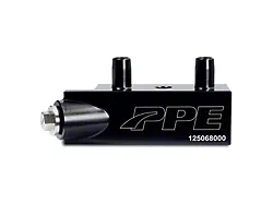
1. Remove the strut for the truck and place the strut into a strut compressor. Make sure to locate or mark the position of the lower eyering sleeve or barpin. Compress the spring to remove tension from the strut top plate. Remove the center nut with a 15mm socket. Retain factory nut. See Photo 1.
2. Remove the strut from the bottom of the assembly as shown in Photo 2.
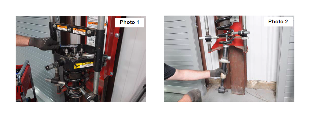
3. Remove the factory lower coil spring isolator from the OEM strut. See Photo 3. *Note* Some models may not be equipped with a lower spring isolator.
4. Twist the shaft on the new supplied strut to unlock the piston from the packaging position. Next place the isolator onto the new supplied strut. See Photo 4.
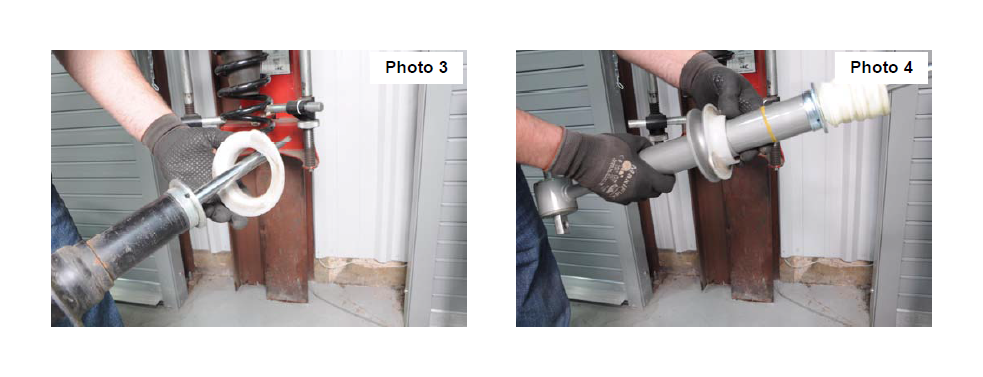
5. Make sure the bump stop is on the new supplied strut and slide the up through the bottom of the factory coil spring and hand tighten the factory nut. Make sure the barpin is located in the same position as the OEM strut. See Photo 5.
6. Using a 15mm socket tighten the center nut on the strut plate. Torque to 33-35 ft-lbs. See Photo 6.
7. Install the strut back into the truck using factory hardware.
8. 3.5” 4wd GM kits will use the supplied hardware in the kit box.