FREE 1 to 3-Day Delivery on Orders $149+ Details
How to Install Rough Country 4.75 in. Suspension & Body Lift Kit w/ Upper Control Arms on Sierra
Installation Time
5 hours
Tools Required
- 18MM Wrench
- 15MM Wrench
- 21MM Wrench
- 11MM Wrench
- 10MM Wrench
- Floor Jack
- Jack stands
- Strut Compressor
- Die Grinder
- 8mm Socket
- 10mm Socket / Wrench
- 11mm Socket / Wrench
- 12mm Socket / Wrench
- 13mm Socket / Wrench
- 14mm Socket / Wrench
- 15mm Socket / Wrench
- 16mm Socket / Wrench
- 18mm Socket / Wrench
- 19mm Socket / Wrench
- 21mm Socket / Wrench
- 22mm Socket / Wrench
- Hand Grinder
- #15, #40, & #45 Torx bit
- Jack
- Jack Stands
- Wood Blocks (2x4)
- Pliers
- Hammer
- Phillips Screwdriver
- Drill Motor
- 1/2” Drill Bit
- Reciprocating Saw

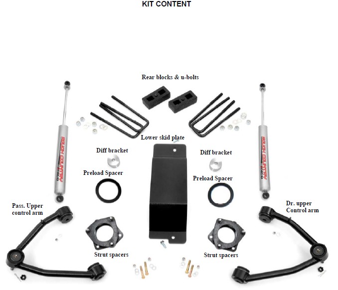
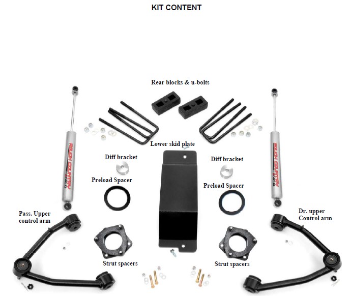
Shop Parts in this Guide
FRONT INSTALLATION
1. Park the vehicle on a level surface and chock the rear wheels.
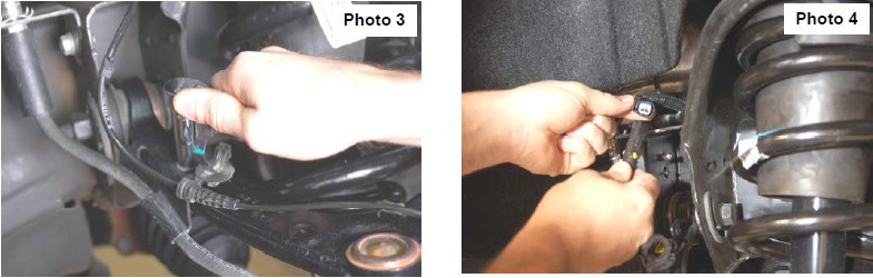
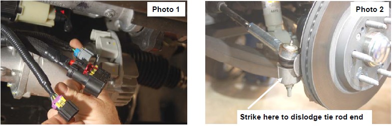
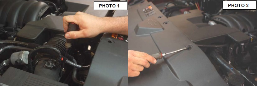
2. Jack up the front of the vehicle. Place jack stands under the frame rails and lower onto jack stands letting the front suspension hang. 3. Remove the tires and wheels. Remove the 6 bolts holding the factory skid plate using a 15mm socket. Unplug the three connectors going to the electric power steering. See Photo 1.
4. Retain factory hardware and front skid plate for reuse.
5. Using a 21mm wrench, remove the tie-rod nut as shown in Photo 2. Strike the front of the mount to dislodge the tie rod end. Remove from the knuckle.
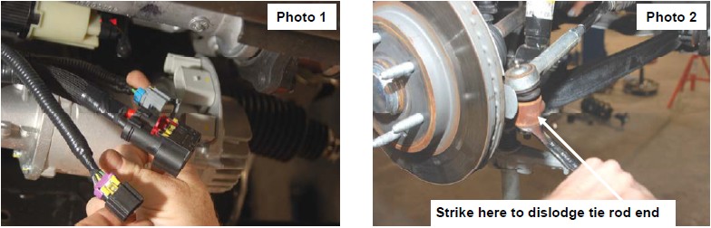
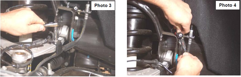
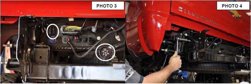
6. Remove the sensor wire from the plastic clip. Remove the brake line bracket from the control arm using a 10mm wrench. See Photo 3.
7. Remove and unplug the ABS sensor wire from the frame as shown in Photo 4.
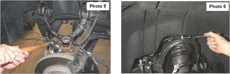
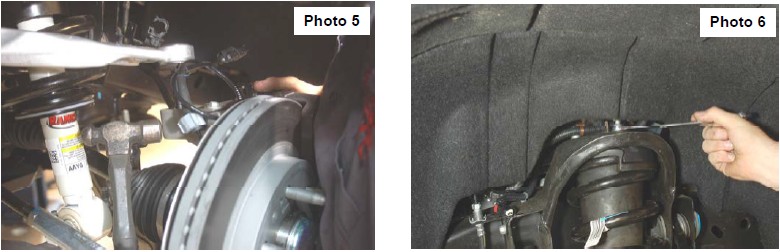
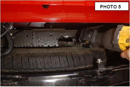
8. Remove sway bar link with 15mm socket and wrench. Place jack stand under knuckle for support and then remove upper ball joint nut using a 18mm wrench. See Photo 5. Strike the knuckle as shown to dislodge the ball joint. Separate the upper control arm from the knuckle.
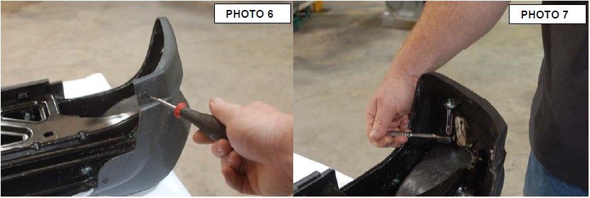
9. Using a 18mm wrench, remove the upper strut nuts as shown in Photo 6. Retain factory hardware for reuse.
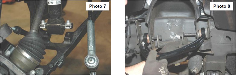
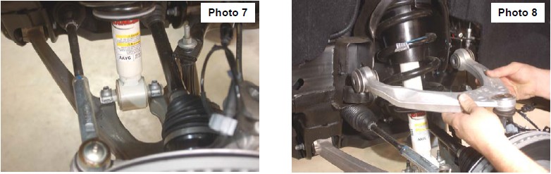
10. Using a 15mm wrench, remove the 2 bolts securing the lower strut mount to the lower control arm and remove the strut from the vehicle. Retain stock hardware. See Photo 7.
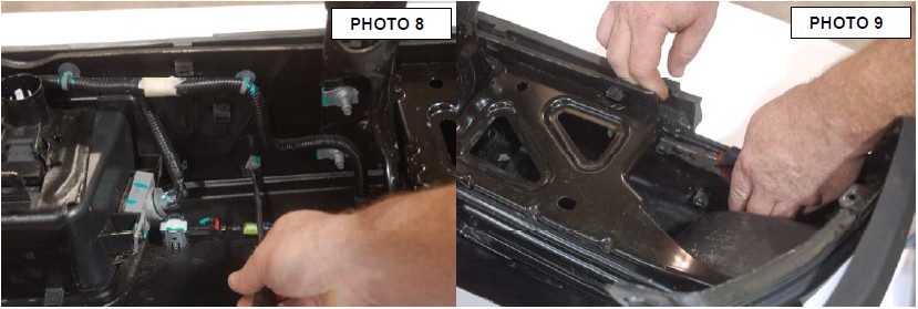
11. Mark location of alignment cams on upper control arms to allow installation of new arm to same position. Using a 21mm wrench and 21mm socket, remove the upper control arms from the vehicle. See Photo 8. Retain the hardware.
12. Using a 18mm socket and wrench remove the four bolts holding in the factory cross member. Retain factory hardware.
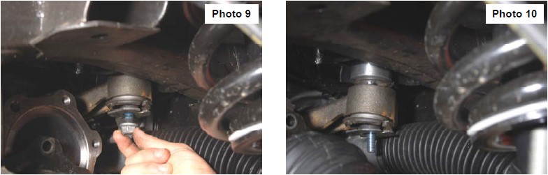
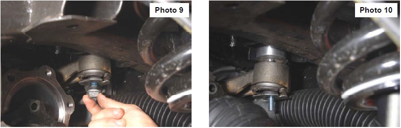
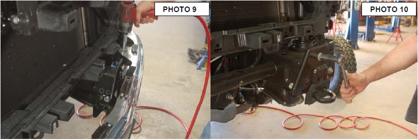
13. Use a jack stand to support the front diff. Remove the front driver and passenger bolts holding the diff mount to the frame with a 15mm and 18mm wrench. See Photo 9.
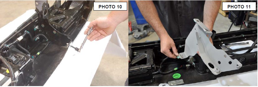
14. Lower the jack stand and pull down on the front of the diff to allow enough room to slide the two aluminum diff drop spacer into place. Use the supplied 7/16” x 5” bolts, lock washers, and nuts. Tighten with a 16mm and 18mm socket and wrench. See Photo 10.
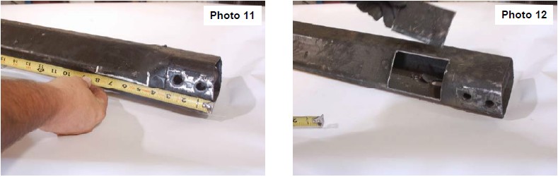
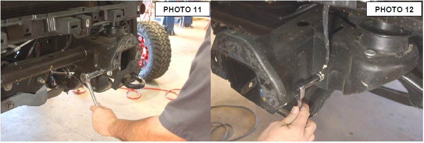
15. On the driver side of the factory cross member measure from the end of the tube and make marks at 4.5” and 8” on the front side as shown in Photo 11. Measure 1/4” for the bottom, and 2” from the back side and mark.
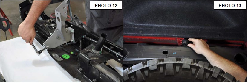
16. Using a die grinder and cut across the marks as shown in Photo 12. Hold the cross member into place and check clearance between the cross member and front diff.
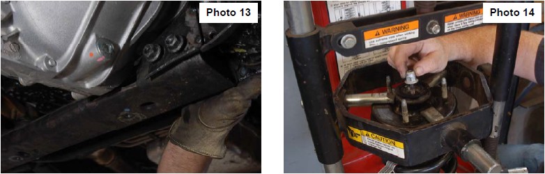
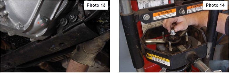
17. Insert factory hardware into the stock cross member and tighten with a 18mm socket and wrench. See Photo 13.
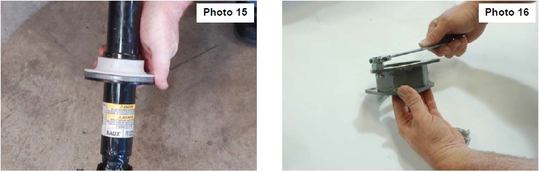
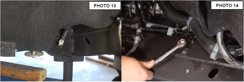
18. Place the strut in a strut compress and apply pressure on the coil spring. Place a alignment mark on the strut top and one end of the lower bar pin, this will be used for later reference. Using a 18mm wrench remove the strut cap nut. Slowly let pressure off the coil spring and disassemble strut. See Photo 14.
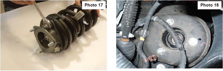
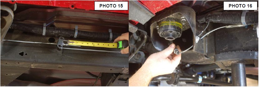
19. Place the supplied preload spacer between the lower coil seat and the plastic isolator ring as shown in Photo 15.
20. Place strut assembly back in spring compress, turn the alignment marks that you made earlier 180 degrees apart. This will turn the bar pin in the correct location when the strut spacer is installed.
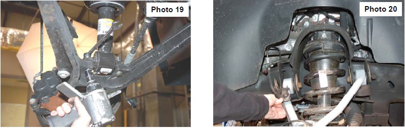
21. Using the supplied 10mm studs place each stud into the smaller sized holes in the strut spacer facing upward. Use the supplied sleeve to slide over each stud to act as a spacer allowing you to pull the stud through the hole with the 10mm nut and a 17mm wrench, locking the stud into place. Remove sleeve and repeat on the other five studs. See Photo 16.
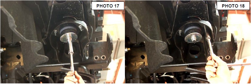
22. Place the strut spacer on top of the stud and tighten using factory hardware and a 18mm wrench. See Photo 17.
27. Install the strut assembly in the factory mount with the supplied 10mm nuts/washers &lock-washers on the upper mount. Tighten using a 17mm wrench. Note: Locking washer must be installed between nut and regular washer on studs. See Photo 18.
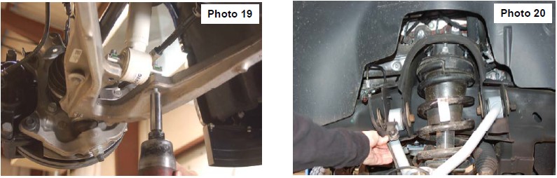
28. Install the strut in the lower control arm using factory hardware and . See Photo 19. It may be necessary to jack up the lower control arm with a floor jack to align lower strut holes.
29. Reinstall the sway bar on the lower control arm using a15mm wrench.
30. Reinstall the knuckle to the upper control arm with the supplied castle nuts/cotter pins. Tighten using 3/4” wrench to 50 ft/lbs. DO NOT OVER-TORQUE THE CASTLE NUT. Reinstall the tie rod end into the knuckle with factory hardware and using a 21mm wench.
31. Install the brake line bracket on the new control arm with the supplied 1/4” lock nut / washer and using a 7/16” wrench. See Photo 20. Driver side shown.
32. Reconnect the ABS wire that was disconnected.
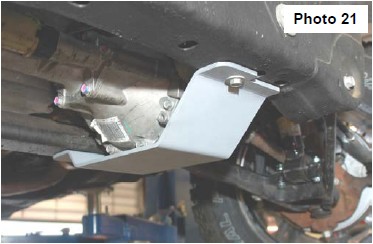
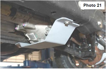
33. Locate and install the new lower skid plate below the differential in the factory location with the factor hardware and using a 15mm wrench. See Photo 21.
34. Reconnect the three connectors going to the electric power steering.
35. Reinstall the wheels/tires.
36. Jack up the vehicle and remove the jack stands.
37. Lower the vehicle to the ground.
REAR INSTALLATION
1. Chock the front wheels.
2. Place a floor jack under the differential and jack up the rear of the vehicle.
3. Place jack stands under the frame rails and lower onto the jack stands.
4. Remove the tires/wheels.
5. Remove the factory shock absorbers using a 21mm wrench & socket. Retain the factory hardware for reuse.
6. Remove the factory u-bolts using a 21mm socket, then remove the factory blocks. Lower the axle using the floor jack to allow for the new 3” block to be installed.

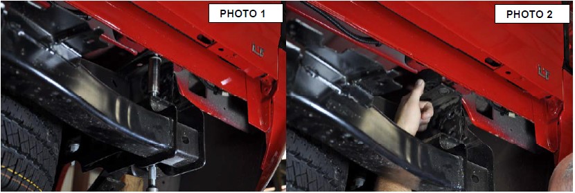
7. Install the block on the factory spring pad with the flat part of the block on the spring and the thinner end towards the front. Jack up the axle to meet the springs, making sure to align the center pin. See Photo 1
8. With the floor jack applying slight pressure to the rear axle to keep the pin aligned, install the new supplied u-bolts and tighten in a crossing pattern, using a 7/8” socket.
9. Locate the new shock absorbers part # 658726, and install the shock absorbers in the factory mounting locations using the factory hardware. Tighten using a 21mm wrench & socket. See Photo 2
10. Install the tires/wheels.
11. Jack up the vehicle to remove the jack stands. Remove the jack stands and lower the vehicle to the ground.
POST INSTALLATION INSTRUCITONS
1. Lightly grease the ball joints. Do not over grease the ball joint as this could cause ball joint boot failure.
2. Have a qualified alignment center align the vehicle immediately.
3. Have headlights adjusted to proper settings.
4. Wheels must be retighten at 50 miles.
5. All kit components must be retightened at 500 miles and then every three thousand miles after installation. Periodically check hardware for tightness.
6. Install “Warning to Driver” decal on sun visor.
7. On some vehicles the front lower skirting will need to be trimmed if using certain wheel /tire combinations and with heavy offset wheels. Trim only as needed.
FRONT INSTALLATION
1. Park the vehicle on a level surface and chock the rear wheels.
2. Jack up the front of the vehicle. Place jack stands under the frame rails and lower onto jack stands letting the front suspension hang.
3. Remove the tires and wheels. Remove the 6 bolts holding the factory skid plate using a 15mm socket. Unplug the three connectors going to the electric power steering. See Photo 1.
4. Retain factory hardware and front skid plate for reuse.
5. Using a 21mm wrench, remove the tie-rod nut as shown in Photo 2. Strike the front of the mount to dislodge the tie rod end. Remove from the knuckle.
6. Remove the sensor wire from the plastic clip. Remove the brake line bracket from the control arm using a 10mm wrench. See Photo 3.
7. Remove and unplug the ABS sensor wire from the frame as shown in Photo 4.
8. Remove sway bar link with 15mm socket and wrench. Place jack stand under knuckle for support and then remove upper ball joint nut using a 18mm wrench. See Photo 5. Strike the knuckle as shown to dislodge the ball joint. Separate the upper control arm from the knuckle.
9. Using a 18mm wrench, remove the upper strut nuts as shown in Photo 6. Retain factory hardware for reuse.
10. Using a 15mm wrench, remove the 2 bolts securing the lower strut mount to the lower control arm and remove the strut from the vehicle. Retain stock hardware. See Photo 7.
11. Mark location of alignment cams on upper control arms to allow installation of new arm to same position. Using a 21mm wrench and 21mm socket, remove the upper control arms from the vehicle. See Photo 8. Retain the hardware.
12. Using a 18mm socket and wrench remove the four bolts holding in the factory cross member. Retain factory hardware.
13. Use a jack stand to support the front diff. Remove the front driver and passenger bolts holding the diff mount to the frame with a 15mm and 18mm wrench. See Photo 9.
14. Lower the jack stand and pull down on the front of the diff to allow enough room to slide the two aluminum diff drop spacer into place. Use the supplied 7/16” x 5” bolts, lock washers, and nuts. Tighten with a 16mm and 18mm socket and wrench. See Photo 10.
15. On the driver side of the factory cross member measure from the end of the tube and make marks at 4.5” and 8” on the front side as shown in Photo 11. Measure 1/4” for the bottom, and 2” from the back side and mark.
16. Using a die grinder and cut across the marks as shown in Photo 12. Hold the cross member into place and check clearance between the cross member and front diff.

17. Insert factory hardware into the stock cross member and tighten with a 18mm socket and wrench. See Photo 13.
18. Place the strut in a strut compress and apply pressure on the coil spring. Place a alignment mark on the strut top and one end of the lower bar pin, this will be used for later reference. Using a 18mm wrench remove the strut cap nut. Slowly let pressure off the coil spring and disassemble strut. See Photo 14.
19. Place the supplied preload spacer between the lower coil seat and the plastic isolator ring as shown in Photo 15.
20. Place strut assembly back in spring compress, turn the alignment marks that you made earlier 180 degrees apart. This will turn the bar pin in the correct location when the strut spacer is installed.
21. Using the supplied 10mm studs place each stud into the smaller sized holes in the strut spacer facing upward. Use the supplied sleeve to slide over each stud to act as a spacer allowing you to pull the stud through the hole with the 10mm nut and a 17mm wrench, locking the stud into place. Remove sleeve and repeat on the other five studs. See Photo 16.

22. Place the strut spacer on top of the stud and tighten using factory hardware and a 18mm wrench. See Photo 17.
27. Install the strut assembly in the factory mount with the supplied 10mm nuts/washers &lock-washers on the upper mount. Tighten using a 17mm wrench. Note: Locking washer must be installed between nut and regular washer on studs. See Photo 18.

28. Install the strut in the lower control arm using factory hardware and . See Photo 19. It may be necessary to jack up the lower control arm with a floor jack to align lower strut holes.
29. Reinstall the sway bar on the lower control arm using a15mm wrench.
30. Reinstall the knuckle to the upper control arm with the supplied castle nuts/cotter pins. Tighten using 3/4” wrench to 50 ft/lbs. DO NOT OVER-TORQUE THE CASTLE NUT. Reinstall the tie rod end into the knuckle with factory hardware and using a 21mm wench.
31. Install the brake line bracket on the new control arm with the supplied 1/4” lock nut / washer and using a 7/16” wrench. See Photo 20. Driver side shown.
32. Reconnect the ABS wire that was disconnected.
33. Locate and install the new lower skid plate below the differential in the factory location with the factor hardware and using a 15mm wrench. See Photo 21.
34. Reconnect the three connectors going to the electric power steering.
35. Reinstall the wheels/tires.
36. Jack up the vehicle and remove the jack stands.
37. Lower the vehicle to the ground.
REAR INSTALLATION
1. Chock the front wheels.
2. Place a floor jack under the differential and jack up the rear of the vehicle.
3. Place jack stands under the frame rails and lower onto the jack stands.
4. Remove the tires/wheels.
5. Remove the factory shock absorbers using a 21mm wrench & socket. Retain the factory hardware for reuse.
6. Remove the factory u-bolts using a 21mm socket, then remove the factory blocks. Lower the axle using the floor jack to allow for the new 3” block to be installed.
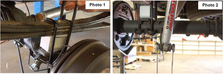
7. Install the block on the factory spring pad with the flat part of the block on the spring and the thinner end towards the front. Jack up the axle to meet the springs, making sure to align the center pin. See Photo 1
8. With the floor jack applying slight pressure to the rear axle to keep the pin aligned, install the new supplied u-bolts and tighten in a crossing pattern, using a 7/8” socket.
9. Locate the new shock absorbers part # 658726, and install the shock absorbers in the factory mounting locations using the factory hardware. Tighten using a 21mm wrench & socket. See Photo 2
10. Install the tires/wheels.
11. Jack up the vehicle to remove the jack stands. Remove the jack stands and lower the vehicle to the ground.
POST INSTALLATION INSTRUCITONS
1. Lightly grease the ball joints. Do not over grease the ball joint as this could cause ball joint boot failure.
2. Have a qualified alignment center align the vehicle immediately.
3. Have headlights adjusted to proper settings.
4. Wheels must be retighten at 50 miles.
5. All kit components must be retightened at 500 miles and then every three thousand miles after installation. Periodically check hardware for tightness.
6. Install “Warning to Driver” decal on sun visor.
7. On some vehicles the front lower skirting will need to be trimmed if using certain wheel /tire combinations and with heavy offset wheels. Trim only as needed.
FRONT INSTALLATION INSTRUCTIONS
1. Disconnect battery using a10mm socket
2. Using a screwdriver disconnect the air filter inlet hose from air box. See Photo 1. Lock the steering wheel and mark upper and lower steering shaft. Remove steering shaft from rack and pinion using a 11mm socket.
3. Remove the ten plastic clips from the radiator bezel using a screwdriver. See Photo 2.
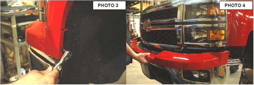
4. Remove the painted bumper bezel from truck using a 7mm socket, remove the two bolts on both side. See Photo 3.
5. Unclip the painted bumper bezel from the grill. There are six clips behind the bumper. Pull the sides of bumper bezel out then pull back to remove. See Photo 4. This may take two people .
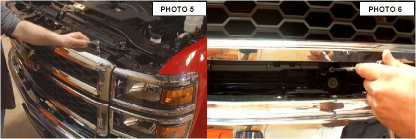
6. Remove the 8 bolts holding the front grill on using a 10mm socket. There are 4 bolts on top See Photo 5 and 4 bolts on bottom See Photo 6 of the grill. There are two clips on each side. Pull straight out to release clips
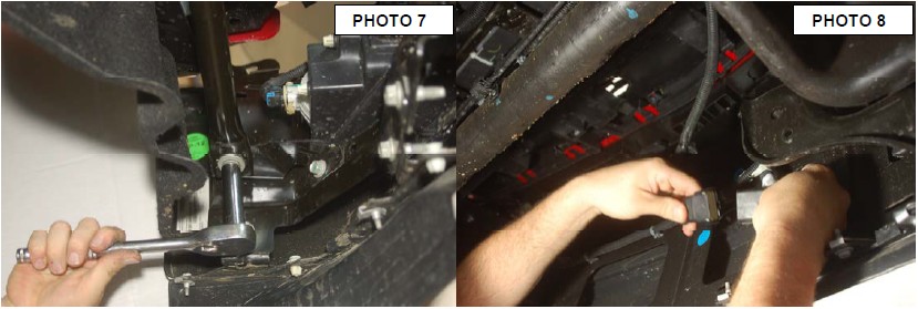
7. Remove the side bumper support bracket using a 15mm socket . See Photo 7.
8. Unplug the fog lights and wiring harness from bumper. See Photo 8.
9. Use a 18mm socket to remove the four bolts holding the bumper on to the frame then remove bumper. See Photo 9.
10. Remove front bumper brackets using a 15mm socket. See Photo 10.
11. Then remove tow hooks using a 18mm socket and wrench. See Photo 11.
12. Using a 10mm socket remove the ground wires from frame. Two of the ground wires are on both front body mounts. See Photo 12.
13. The other ground wire is on passenger side body mount behind the tire. See Photo 13.
14. Remove the O2 sensor wire clip from frame just above passenger side body mount. On driver side remove the wiring loom bracket using a 13mm socket. See Photo 14. Remove the wire clips from the top of strut bolts.
15. Measure the emergency brake cable adjustment bolt from back of nut to the end of threads and record this measurement for later use. ( Should be about 2.5” ). See Photo 15.
16. Then adjust bolt to allow slack so the brake cable can be disconnected. Then release the metal clips holding the emergency cable to frame on body mount. See Photo 16.
17. Loosen the front body mount bolts using a 18mm socket and a 21mm on the other body mount bolts. See Photo 17. Remove the nuts from the body bushing using a 15mm socket. See Photo 18. Only remove the bolt on one side at a time. Lift the body off of frame just enough to remove body bushing. Look an make sure no other wires or brake lines are being stretched. Front body mount bolt must come out from the top.
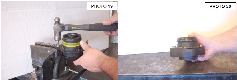
18. Once the bushing is out knock the two studs out using a hammer and vise. See Photo 19. Replace the two stud with the supplied 3/8” x 2.25” bolts, washers, and nuts. Install cab body puck on body bushing and place on truck. See Photo 20.
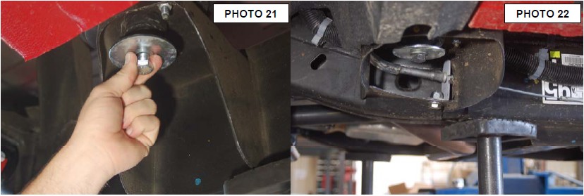
19. Install the 1.25” x 3” round body puck onto of rear cab body bushing. Use a 14mm socket and wrench to tighten new bolt. Lower body onto body bushing and install body bolts but do not tighten at this time. Install a new rear cab bolt 14mm x 140mm. See Photo 21. Repeat step for other side. Make sure the wiring does not get pinch under the flag bolt on the two front body mounts while installing. Once all body puck are in tighten all bolts using 19mm for front body bolts 21mm for middle bolts and 22mm for rear cab bolts.
20. Install emergency brake line bracket using the supplied 1/2” x 1” bolt, washer, and nut. Use a 19mm socket and wrench to tighten. See Photo 22. Reconnect the emergency brake cable. Take a 1/4 off inch off the original measurement taken adjust the parking brake cable to around 2.25” from the back of the nut to the end of the threads.
21. Reinstall ground wires and O2 sensor clip back onto frame using 10mm socket. Ground wire on passenger side body mount be hide tire will need a clip removed to get slack in wire.
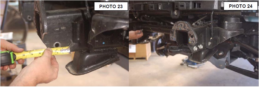
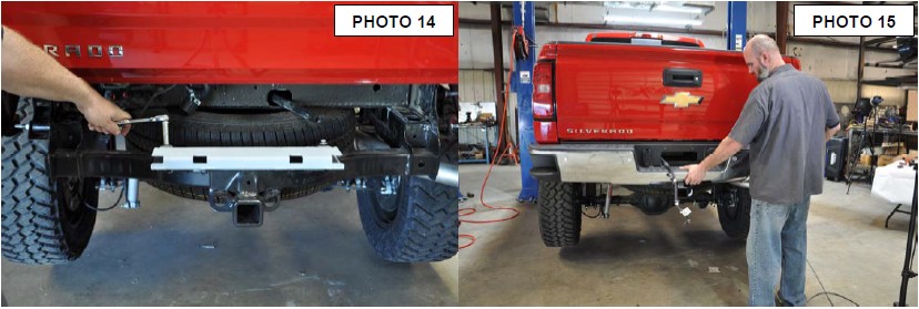
22. On the front frame horns measure the tow hook mounting hole on the side with only one hole 1 1/2” back and 1 3/16” up from bottom of frame. See Photo 23. Mark the area and drill a new hole for the tow hooks using a 1/2 drill. Flip the tow hooks and install bolts. Tighten using 18mm socket. See Photo 24.
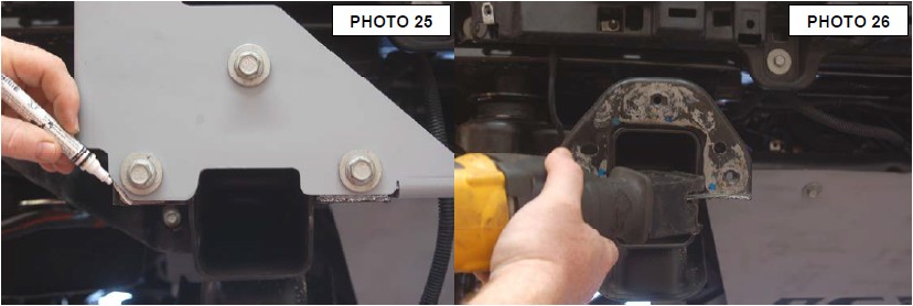
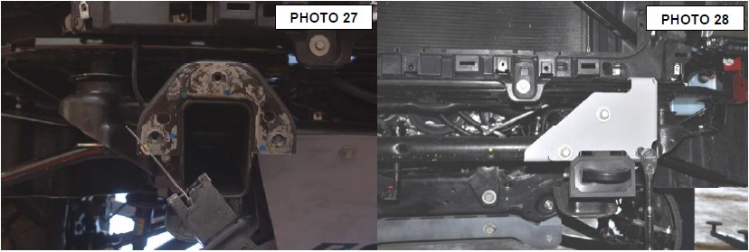
23. Install new front bumper brackets using stock hardware, push up on the bracket when you tighten the bolts. Using the bracket for a template mark and remove the lower inside of frame horn and out side corners. Use a sawzall or cut off wheel to remove the material. See Photo 25, 26, and 27.
24. After cutting reinstall the bumper bracket with factory bolts and the supplied 10mm x 30mm button head bolt and washer for the outside hole. Pull up on the bracket and tighten bracket using a 15mm socket and a 6mm allen wrench. See Photo 28.
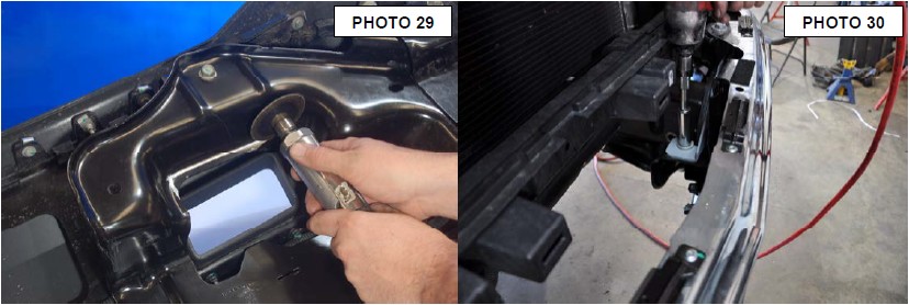
25. On the inside of the front bumper where the tow hooks holes are measure 1/4 down on the inner bumper bracket and cut even with the sides of the holes. See Photo 29.
26. Install front bumper using stock hardware with the supplied 12mm nuts. Use a 18mm socket and wrench to tighten bumper bolts. See Photo 30.
27. Reinstall front grill using stock hardware and a 10mm socket to tighten all 8 bolts. Reinstall painted bumper bezel using stock hardware. Reinstall steering shaft using a 15mm. Reconnect air inlet hose to air box. Reinstall radiator bezel using the stock plastic clips.
28. Tighten the side bumper support bracket using a 15mm socket. Push the bracket up while tightening the bolts
BED/REAR BUMPER INSTALLATION INSTRUCTIONS
**Note** The bumper is removed in the first three pictures to help show locations for the bolts and electrical plugs. The bumper is not removed until step 3.
1. Loosen the 8 bolts holding the bed on using a 18mm socket. See Photo 1. Remove the six rear bolts on bed leaving the front bolts near cab in but loose. Lift the rear of bed up just enough to place one of the body puck between frame and bed. This is done so rear bumper can be removed. See Photo 2.
2. Unplug the rear bumper wiring from the junction box on the frame and unplug the 7 way connector from bumper. See Photo 3.
3. With the license plate remove reach be hide the bumper and remove the two bolts using a 13mm wrench. One is on the left and one on the right. Using a 15mm, 18mm and a 21mm socket remove bumper bolts. See Photo 4. ( note bumper was remove to show better picture). Remove bumper and place on a clean surface.
4. Mark and cut the tap off the frame for the spare tire tube. Cut straight across the top making the top flat with no ridge. See Photo 5.
5. Using a torx 15 to remove lower bumper screws from the plastic bumper cover. See Photo 6.
6. Using a 7mm socket remove the screws from the inside of bumper. See Photo 7.
7. Using a screwdriver remove the metal clips from the plastic bumper cover. There will be five metal clips to be removed. See Photo 8.
8. Using a pair of pliers to release the plastic clips holding the bumper cover to metal part of the bumper, while pulling on the bumper cover to separate. Only remove enough to allow removal of bumper mounting bracket. See Photo 9.
9. Using a 45 torx remove the five bolts holding the bumper mounting bracket. See Photo
10. 10. Remove the threaded body clip from the stock bumper brackets and place clips in the same area on the new supplied bumper brackets. See Photo 11.
11. Install new bumper brackets using stock hardware and a 40 torx to tighten. See Photo 12.
12. Reassemble rear bumper
13. Remove the body puck from the rear of bed that was place to help remove the bumper and install the bed bolts on one side of the truck to hold the bed in place while installing bed pucks. Hand tighten bolts. Remove the bolt from front of bed that was left loose earlier.
14. Lift one side of the bed at a time and install the five 1 1/4 body pucks. See Photo 13. Use the supplied 12mm bolts, washers. Repeat this step for other side. Use a 19mm socket to tighten bed bolts
15. Install rear bumper step support bracket using the stock hardware. Use a 13mm socket to tighten. See Photo 14.
16. Reinstall rear bumper using stock hardware. See Photo 15. Make sure spare tire tube go back in bumper correctly.
17. Plug in the 7 way connector and bumper wiring. Tighten bumper using a 15mm, 18mm and a 21mm sockets. Make sure bumper is level
18. Reconnect battery