FREE 1 to 3-Day Delivery on Orders $149+ Details
How to Install Mopar Pyrometer Gauge - Digital Stepper Motor - Black on your Dodge Ram
Read instruction thoroughly to verify all required parts are there before installing this product.
Contents:
For Pyrometer Gauge
1 - Wire Harness – 10 ft. - Includes Attached 3⁄ 16" Probe
1 - Hose Clamp (adjustable) – 2½" – 3½"
2 - Set Screws
1 - Pyrometer Probe Adapter - Clamp On
1 - Pyrometer Probe Adapter - 1⁄ 8" NPT
2 - Aluminum Thumb Nuts
1 - Mounting Bracket
2 - Lock Washers
1 - Rubber Grommet
Important
Pyrometers are sensitive, high accuracy instruments. They must be handled and installed with care to insure proper performance. Carefully read and follow these instructions, and your pyrometer will provide you with a long and accurate life.

INSTALLATION
1. Check that you have all parts required for installation, and the engine is cool.
2. Disconnect the negative (-) battery cable.
3. Gauge mounts in a 2 1/16” hole. Use supplied brackets and nuts to secure gauge to dash.
4. Drill 1” diameter hole where wires pass through sheet metal (such as firewall) and install rubber grommet provided. (Grommet will require slit.)
5. Connect the white wire to dash lighting or switchable 12v light source.
PROBE INSTALLATION
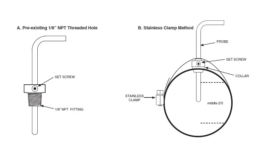
1. Begin by installing the thermocouple in the exhaust, then work back to the gauge. Installing the probe in the proper location will insure optimal temperature readings. For non-turbo engines, install the probe 1-2 inches from the cylinder head. For turbo engines, remove the exhaust manifold and install the probe 1-2 inches from the cylinder head. If the exhaust manifold can not be removed, install the probe 1-2 inches after the turbo exhaust outlet (Exhaust gas temps could drop over 200˚ when installing after the turbo). CLEAN ALL METAL FILINGS out of the exhaust manifold. Metal filings will damage the turbo impellor if they go through the turbo. The probe can be mounted in two different ways, so please use the method best suited for your needs.
A) Pre-existing 1/8” NPT Threaded Hole: Simply screw the threaded fitting into the hole, insert the probe, and tighten the set screw snugly onto the probe. (Caution: do not over tighten set screw or damage to probe may occur.) Make sure the probe is oriented so the wires do not come in contact with, or become too close to the manifold or other hot engine parts. See illustration for details.
B) Stainless Clamp Method: This method is for applications that require frequent removal of the manifold or header for service, or just faster and easier installation. Drill a 7/16” diameter hole about 6” down from the junction of the exhaust pipe to manifold junction. Undo the clamp and slide the probe into the hole in the clamp. Slide the set screw collar onto the probe. Before tightening the collar in position make sure that when inserted, the probe will have it’s tip in the middle two-thirds of the exhaust stream. Tighten screw collar in position. (Caution: do not over tighten set screw or damage to probe may occur.) Hold the clamp open when inserting the probe into the 13/32” hole. Re-join the clamp ends and tighten in position. Make sure the probe is oriented so the wires do not come in contact with, or become too close to the manifold or other hot engine parts. See the illustration below for details.
2. With the probe installed, the wire harness can now be routed to the gauge. The wire harness is an integral part of the pyrometer calibration. It may not be shortened or lengthened without affecting the gauge calibration. You will need to determine a suitable location to coil the excess wire, and tie it loosely with a wire tie. (Loosely tying the excess coil prevents embritlement caused by vibration.) Pass the harness through the fire wall using an existing hole, or drill a 1” diameter hole and use the rubber grommet provided to protect the wire from damage.
Power-Up
The pointer will move backward to the stop pin and then display actual temperature. This procedure is an auto-calibration function and is performed on every power-up. While this test is being performed, the gauge may make a clicking sound. This is normal.