FREE 1 to 3-Day Delivery on Orders $149+ Details
How to Install K&N Blackhawk Cold Air Intake on your Sierra

Shop Parts in this Guide
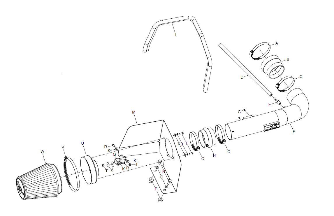
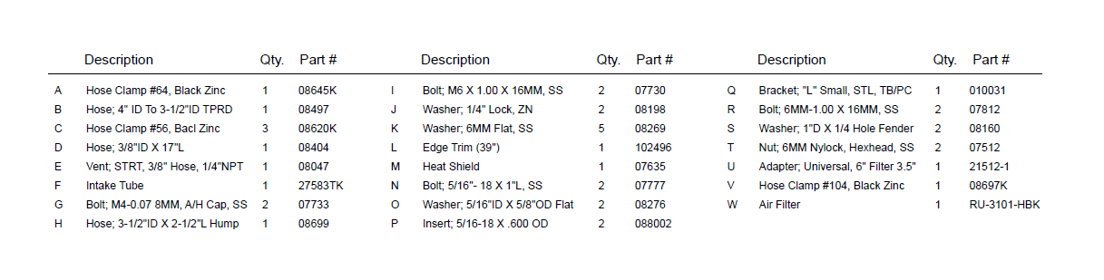
PARTS LIST:
NOTE: FAILURE TO FOLLOW INSTALLATION INSTRUCTIONS AND NOT USING THE PROVIDED HARDWARE MAY DAMAGE THE INTAKE TUBE, THROTTLE BODY AND ENGINE.
TO START:
1. Turn off the ignition and disconnect the negative battery cable
NOTE: Disconnecting the negative battery cable erases pre-programmed electronic memories. Write down all memory settings before disconnecting the negative battery cable. Some radios will require an anti-theft code to be entered after the battery is reconnected. The anti-theft code is typically supplied with your owner’s manual. In the event your vehicles’ anti-theft code cannot be recovered, contact an authorized dealership to obtain your vehicles anti-theft code..
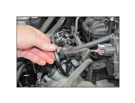
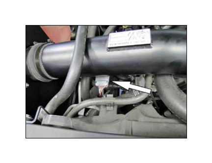
2. Disconnect the mass air electrical connection.
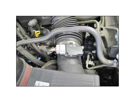
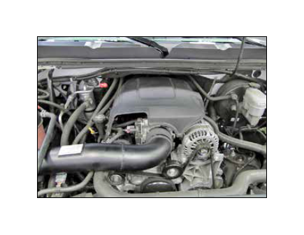
3. Lift up on the engine cover and remove as shown.
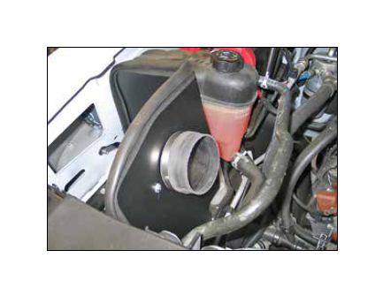
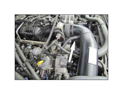
4. Unhook the radiator hose mount from the intake tube.
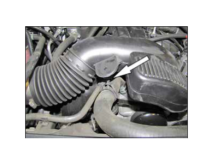
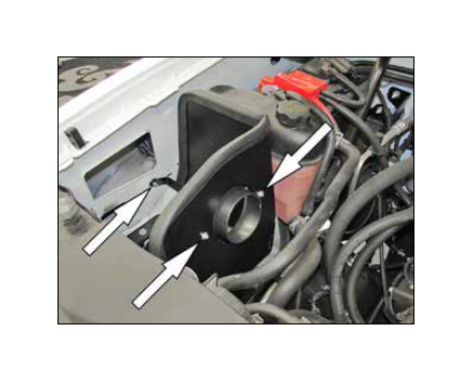
5. Unhook the crankcase vent line from the intake tube plenum as shown.
6. Loosen the hose clamps which secure the stock intake tube, then remove the intake tube from the vehicle.
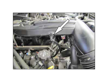
7. Rotate the crankcase vent line counter clockwise on the valve cover port, and then release the locking tab and remove the crankcase vent line from the valve cover.
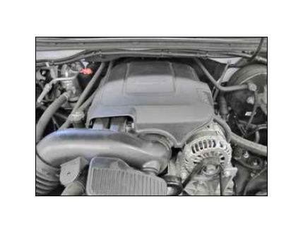
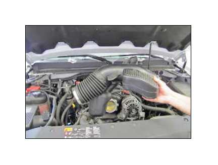
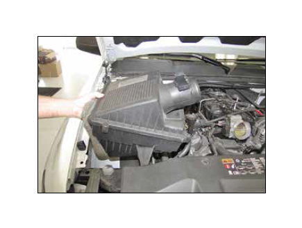
8. Pull firmly upward to release the air cleaner assembly from the mounting tray grommets. Then remove the assembly as shown. NOTE: K&N recommends that customers do not discard factory air intake.
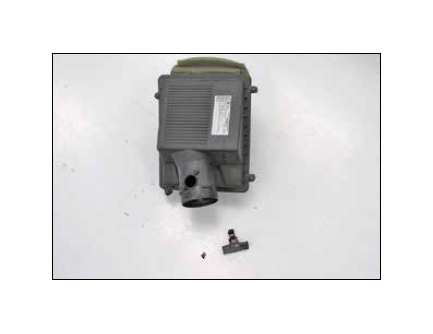
9. Remove the two screws securing the mass air sensor to the air box and then remove the mass air sensor from the air box as shown.
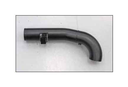
10. Install the mass air sensor into the K&N® intake tube and secure with the provided hardware.
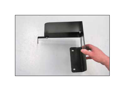
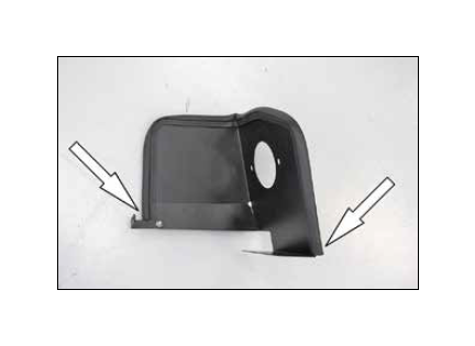
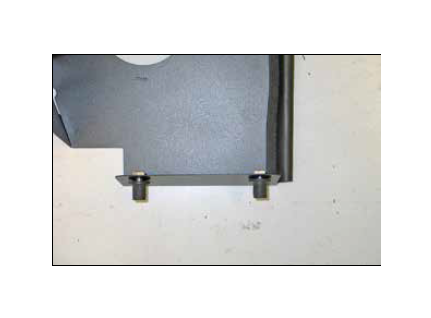
11. Install heat shield mounting bracket (#010031) onto the heat shield as shown using the provided hardware.
12. Install the provided edge trim onto the heat shield as shown. Note: Some trimming will be necessary.
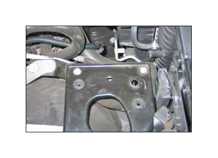
13. Remove the air box mounting grommet shown from the air box mounting plate.
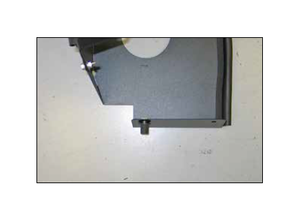
14. Secure the 5/16” inserted nut to the heat shield as shown.
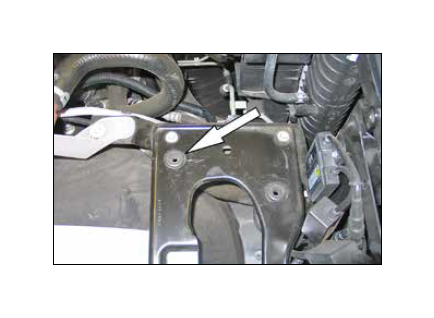
15. Set the heat shield assembly into position with the inserted nut installed into the air box mounting grommet location. Mark the heat shield mounting location to be drilled.
NOTE: Some vehicles may already have this hole in the mounting plate, if the vehicle is already equipped with the hole, skip to step #17.
16. Remove the heat shield assembly and drill a 5/8” hole at the marked location.
17. Install the reaming 5/16” inserted nut into the heat shield as shown.
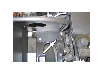
18. Reinstall the heat shield assembly onto the air box mounting plate and secure the two 5/16” bolts provided.
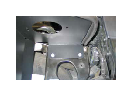
19. Secure the mounting bracket to the inner fender with the hardware provided. Then Install the filter adapter onto the heat shield and secure with the provided hardware.
20. Install silicone hose (#08699) onto the filter adapter and secure with the provided hose clamp.
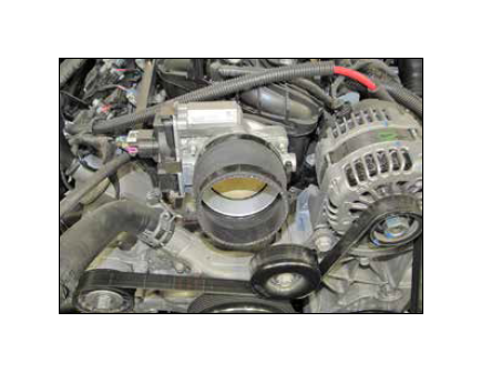
21. Install silicone hose (#08497) onto the throttle body and secure with the provided hose clamp.
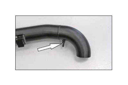
22. Install the provided ¼” NPT fitting into the K&N® intake tube as shown.
NOTE: Plastic NPT fittings are easy to cross thread. Install the vent fitting “hand” tight, then turn it two complete turns with a wrench.
23. Install the K&N® intake tube into the silicone hose at the filter adapter and then into the silicone hose at the throttle body, then secure with the provided hose clamps.
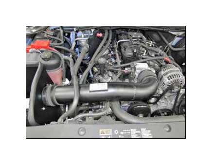
24. Install the provided crankcase vent hose onto the valve cover vent port and then connect the remaining open end to the ¼” NPT fitting in the K&N® intake tube.
25. Install the K&N® air filter onto the filter adaptor and secure with the provided hose clamp.
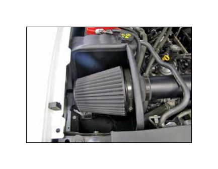
26. Reconnect the mass air electrical connection.
27. Reinstall the engine cover.
28. Reconnect the vehicle’s negative battery cable. Double check to make sure everything is tight and properly positioned before starting the vehicle.
29. The C.A.R.B. exemption sticker, (attached), must be visible under the hood so that an emissions inspector can see it when the vehicle is required to be tested for emissions. California requires testing every two years, other states may vary.
30. NOTE: Most General Motors vehicles have the Vehicle Emissions Certification Information (VECI) label affixed to the air filter box. In order to be compliant with California emissions laws, the label MUST remain in the engine compartment. If the Vehicle Emission Control Information label is removed during modification, a new replacement label must be obtained and installed in a readily visible position in the engine compartment. The label shall not be affixed to any equipment which is easily detached from the vehicle. We recommend that the label is affixed to the underside of the hood adjacent to the hood latch. The label is Vehicle Identification Number dependent and can be ordered from the vehicle dealership. In order to receive the proper decal please bring your VIN with you. Failure to have the VECI under the hood may result in failure of a pre-registration smog test.
31. It will be necessary for all K&N® high flow intake systems to be checked periodically for realignment, clearance and tightening of all connections. Failure to follow the above instructions or proper maintenance may void warranty.
ROAD TESTING:
1. Start the engine with the transmission in neutral or park, and the parking brake engaged. Listen for air leaks or odd noises. For air leaks secure hoses and connections. For odd noises, find cause and repair before proceeding. This kit will function identically to the factory system except for being louder and much more responsive.
2. Test drive the vehicle. Listen for odd noises or rattles and fix as necessary.
3. If road test is fine, you can now enjoy the added power and performance from your kit.
4. K&N Engineering, Inc., requires cleaning the Blackhawk InductionTM intake system’s air filter element every 100,000 miles. When used in dusty or off-road environments, our filters will require cleaning more often. We recommend that you visually inspect your filter once every 25,000 miles to determine if the screen is still visible. When the screen is no longer visible some place on the filter element, it is time to clean it. To clean, purchase our Synthetic Filter Cleaner, part number 99-0624 and follow the easy instructions.