FREE 1 to 3-Day Delivery on Orders $149+ Details
How to Install SLP 1900 TVS 520 HP Supercharger on your Sierra
Installation Time
1 days
Tools Required
- 1/4” and 3/8” Drive Ratchets with Extensions
- Metric and Standard Socket Sets (short and deep recommended)
- Metric and Standard Wrench Sets
- 3/8” Drive Torque Wrench (7-35 ft-lb range)
- Hex Key Set
- 2” Hole Saw and Drill motor
- Coolant (meeting GM standards)
- 6” Scale, Tape Measure, or Other Measuring Device
- Brake Parts Cleaner
- Assembly Lubricant (White Lithium Grease or Petroleum Jelly)
- Electrical Tape
- Sharp Knife or Razor Blade
- Trim Pad Tool (for pushpin removal)
- Fender Cover (2)
- 3/8” Split Loom Convolute
- Harness Wrap Tape
- Medium Strength Thread Locker - Loctite 242 (Blue) or equivalent
VEHICLE CALIBRATION INFORMATION
THIS KIT WAS SHIPPED WITH AN UNPROGRAMMED SCT HAND HELD PROGRAMMING DEVICE (7416-INST). THE DEVICE MAY NOT HAVE THE LATEST SOFTWARE INSTALLED. FAILURE TO UPDATE SCT DEVICE MAY RESULT IN ECM DAMAGE. PRIOR TO BEGINNING THE INSTALLATION OF THIS KIT, PLEASE PROCEED WITH THE FOLLOWING STEPS. THIS SHOULD BE DONE IN ADVANCE OF ANY VEHICLE DISASSEMBLY TO AVOID DELAYS DURING YOUR INSTALLATION. CALIBRATION SUPPORT IS PROVIDED MONDAY – FRIDAY 8 AM TO 5 PM EST.
UPDATING SCT DEVICE
1) Make sure you have the SCT Updater Software installed on your Windows PC. If you do not have it follow this link: http://www.sctflash.com/software/SCTDeviceUpdater.exe.
2) After downloading and installing the update software, open the program. There should be an icon on the desktop.
3) Once Updater is open on your desktop. Plug in your device.
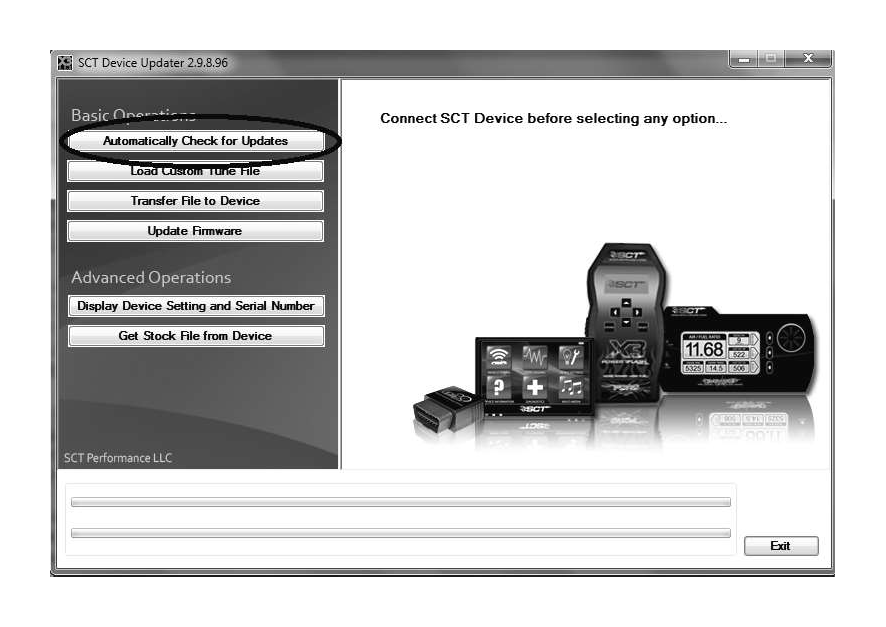
4) With the device plugged in select Automatically Check for Updates from the Basic Operations menu.
5) Your device should start to Update. Notice the bottom bar it will let you know what part of the update it’s on. This can take some time so be patient. Your internet connection and computers speed can impact updating times. Average time is 5-10 minutes.
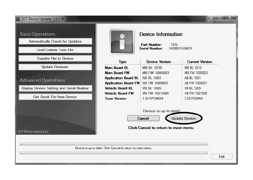
6) You know you are done when SCT Device Updater displays "Device is up to date”.
OBTAINING YOUR FACTORY CALIBRATION
1) Plug the SCT programmer (7416) into the OBD port of the vehicle the supercharger kit will be installed into.
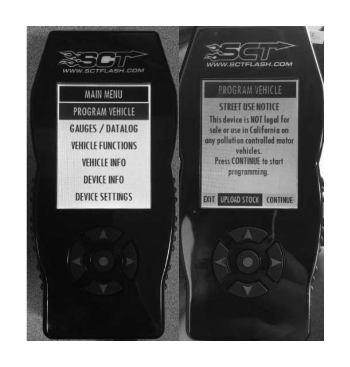
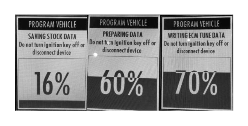
2) Select “Program Vehicle” from the menu screen. Select “Upload Stock” to accept the terms of usage.
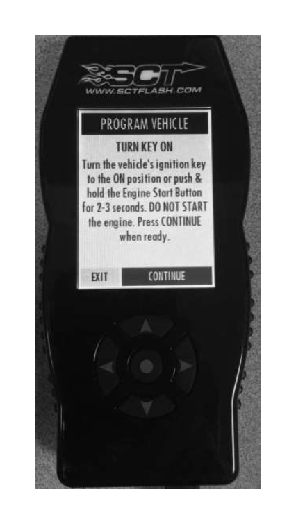
3) When prompted, turn the ignition to the KEY ON position and press “Continue”. DO NOT START THE ENGINE.
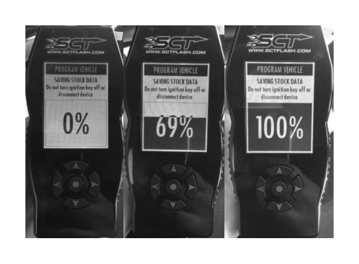
4) Wait for the programmer to finish saving stock data.
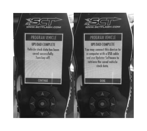
5) Turn the ignition to the KEY OFF position, press “Continue” and wait for the vehicle to power down.

6) The upload is now complete. Press “Continue” and then “Done”.
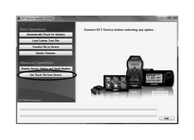
7) You may now disconnect the programmer from the vehicle, re-connect it to your Windows PC and open the same update software used in step 2 of “Updating SCT Device”.
8) Select the “Get stock file from device”.
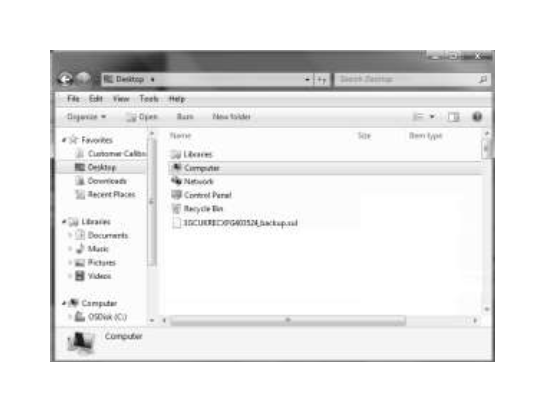
9) Select “Browse” and save the stock file to your desktop.
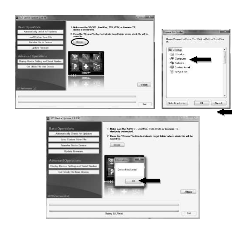
10) Add the text “backup” to the file name that contains the VIN number and e-mail a copy of the file to “[email protected]” .
In the e-mail subject line write: Calibration Request for Kit # XXXXXX (Enter Kit PN)
11) SLP will reply to your e-mail within one business day (Monday to Friday, 8 am to 5 pm EST) with the calibration file for your vehicle.
12)FAILURE TO FOLLOW THE ABOVE STEPS MAY DELAY THE INSTALLATION OF THIS KIT. SLP NEEDS THIS DATA IN ORDER TO PROVIDE YOU WITH THE LATEST CALIBRATION FILES AVAILABLE FOR YOUR VEHICLE. IF YOU HAVE A NEW MODEL YEAR VEHICLE THAT IS NOT YET AVAILABLE IN OUR DATABASE, THE TURN AROUND TIME FOR THE CALIBRATION MAY EXCEED 1 BUSINESS DAY. IF THE CALIBRATION IS NOT YET SUPPORTED, SLP WILL NOTIFY YOU OF THIS DELAY AS TO NOT CAUSE YOUR VEHICLE FROM BEING IMMOBILIZED DURING THIS TIME.
13) Save a copy of the file attached to the e-mail sent back from SLP to the desktop of your PC. This is your new calibration file.
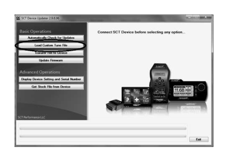
14) Plug the SCT device into your PC.
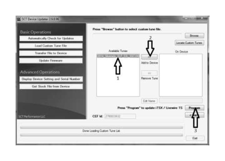
15) Open the SCT Updater Software and select “Load Custom Tune File”.
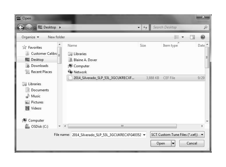
16)Then select “Locate Custom Tune”.
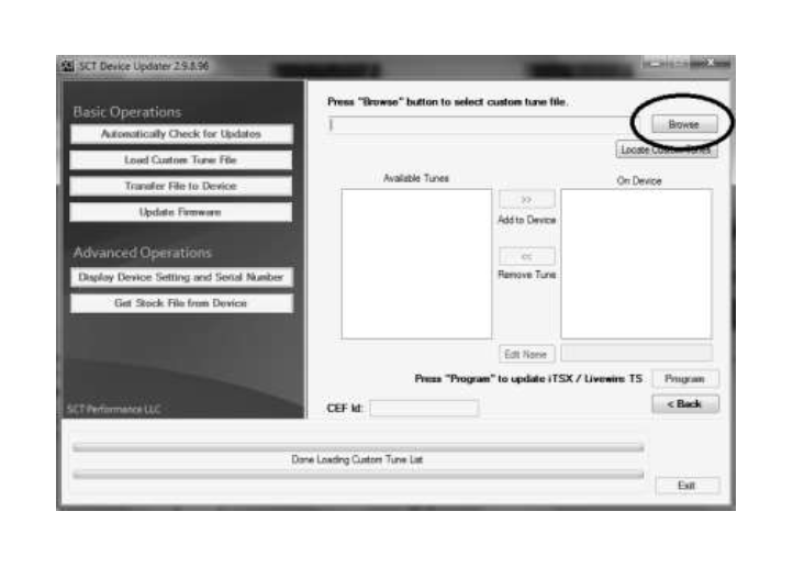
17) Locate and open the file that was attached in the e-mail sent back from SLP on the desktop of your PC.
18) Select the tune from the left column (#1), next select the right arrows (#2) then
“Program” (#3).
19) Your device is now ready to reprogram the vehicle.
PROGRAMMING THE VEHICLE
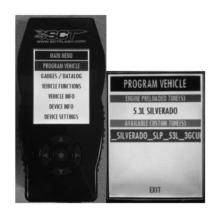
1) Plug the SCT programmer (7416-INST) into the OBD port of the vehicle that is to be calibrated.
2) Select “Program Vehicle” from the menu screen. Select the SLP custom tune.
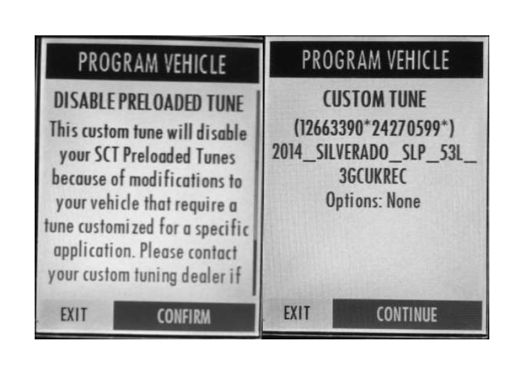
3) Select “Confirm”, then “Continue”.
4) Wait for the programmer to finish the flashing process.
5) When prompted, turn the ignition key to the “Off” position and unplug the SCT programmer from the OBD port.
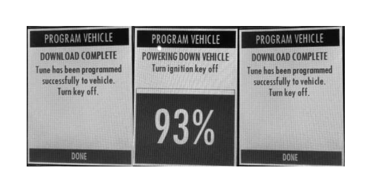
6) Select “Done”. Programming is now complete.
INFORMATION ABOUT THE SUPERCHARGER BYPASS OPERATION
There is a great deal of misinformation about the function of supercharger bypass systems. The supercharger is a positive-displacement pump; that is, so long as it is rotating, it is always pumping air. During low demand or high vacuum operation (i.e. idle, deceleration, and light throttle cruise), the pumping action is undesirable as it creates unwanted heat and noise. The bypass circuit, when open, prevents any pressure buildup across the supercharger and allows air to circulate through the rotors, allowing the supercharger to “idle” freely during these conditions. This results in reduced noise, and by reducing heat buildup in the intake, significantly improves street and strip performance. As throttle demand increases, the bypass circuit is closed, resulting in full performance from the supercharger. The bypass circuit is never used to limit or control boost during full-throttle operation and defeating or altering the bypass function will not result in improved performance in any condition, and will result in poor drivability.
SAFETY PRECAUTIONS
STOP! CAREFULLY READ THE IMPORTANT SAFETY PRECAUTIONS AND WARNINGS BEFORE PROCEEDING WITH THE INSTALLATION!
Appropriate disassembly, assembly methods and procedures are essential to ensure the personal safety of the individual performing the kit installation. Improper installation due to the failure to correctly follow these instructions could cause personal injury or death. Read each step of the installation manual carefully before starting the installation.
Always wear safety glasses for eye protection.
Place the ignition switch in the OFF position.
Always apply the parking brake when working on the vehicle.
Block the front and rear tire surfaces to prevent unexpected vehicle movement.
If working without a lift, always consult vehicle manual for correct lifting
specifications.
Operate the engine only in well-ventilated areas to avoid exposure to carbon monoxide.
Do not smoke or use flammable items near or around the fuel system.
Use chemicals and cleaners only in well-ventilated areas.
Batteries can produce explosive hydrogen gas which can cause personal injury. Do not allow flames, sparks or flammable sources to come near the battery.
Keep hands and any other objects away from the radiator fan blades.
Keep yourself and your clothing away from moving parts when the engine is running.
Do not wear loose clothing or jewelry that can be caught in rotating or moving parts.
Allow the engine, cooling system, brakes and exhaust to cool before working on a
vehicle.
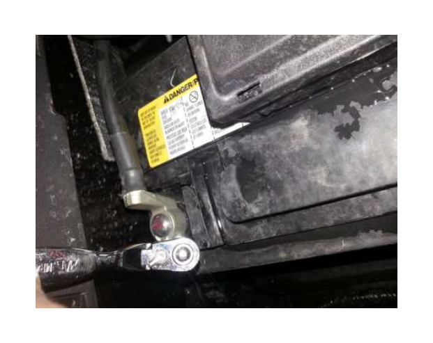
Disconnect both the Negative (-) and Positive ( ) Battery Terminal Leads (in this order) to reduce the risk of electric shock.
SECTION A – DISASSEMBLY
The following section will guide you through the disassembly of the stock components. Special care should be taken to label fasteners and parts that are taken off during this procedure since many will be reused:
1. Plug the provided SCT programmer (7416-INST) into your vehicle and make a copy of the factory calibration file prior to the disassembly of any components on the vehicle. Refer to pages 2 thru 9 of this manual. Failure to complete this step prior to dismantling vehicle may result in a delay of your build due to calibration files not being available.
2. Cover both fenders with fender covers to protect the vehicle finish.
WARNING: Do not smoke or carry lighted tobacco or open flame of any type when working on or near any fuel-related components. Highly flammable mixtures are always present and can be ignited, resulting in personal injury.
a. Remove the engine cover.
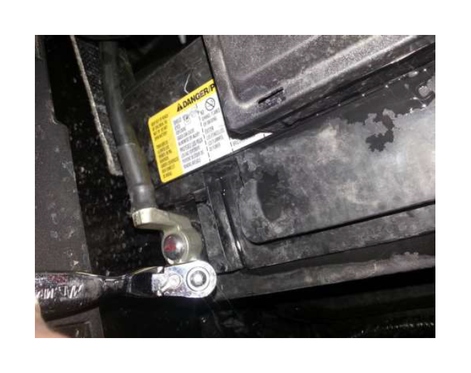
3. Using a 10mm socket, disconnect the (-) negative & ( ) positive connections to the battery.
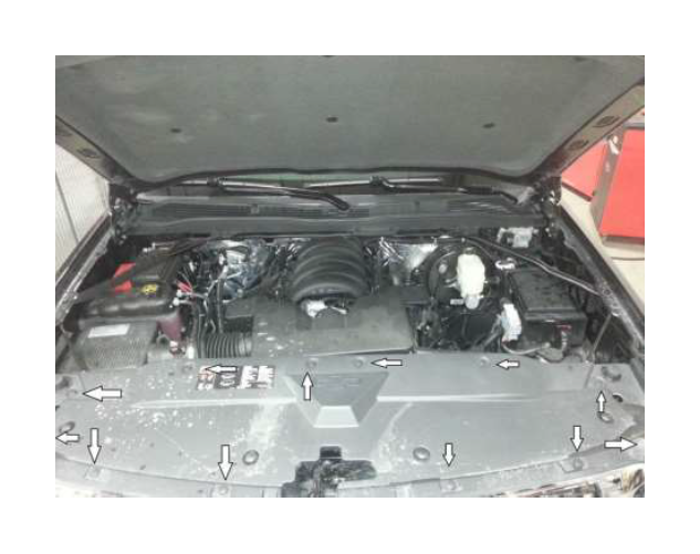
4. Remove the (12) push pins securing the upper radiator closeout panel.

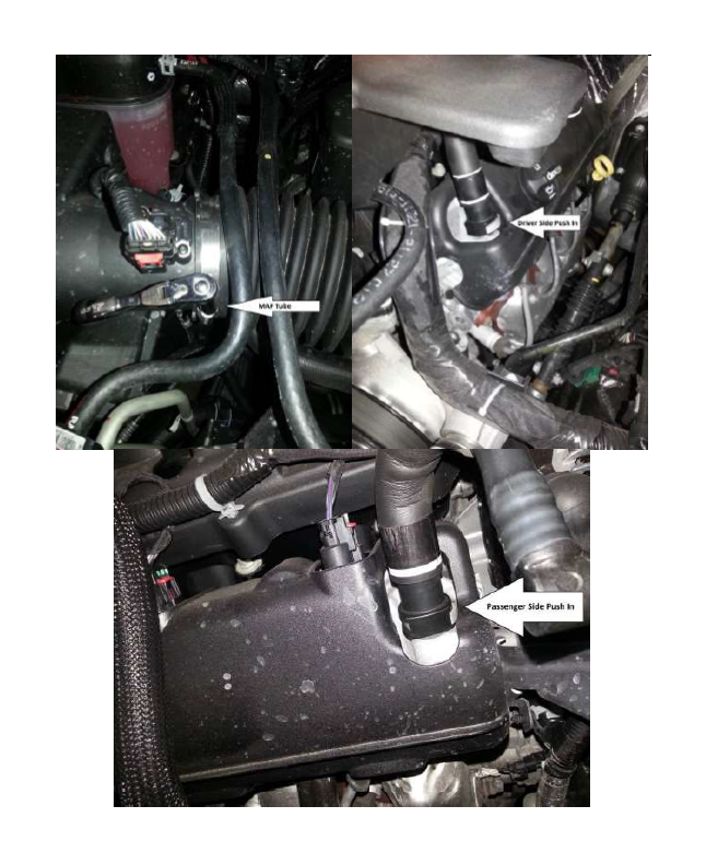
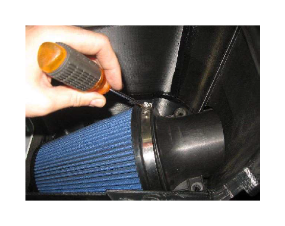
5. Loosen the worm drive clamps (8mm) that secure the clean air tube to the throttle body and MAF tube. Remove the PCV line from the front of the passenger side valve cover. Remove the PCV line from the driver’s side valve cover. Remove clean air tube from vehicle.
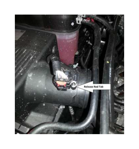
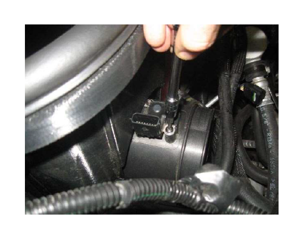
6. Disconnect the Mass Air Flow (MAF) sensor electrical connector from the MAF Sensor on the air box, by pulling the red locking tab back and pressing the release tab.
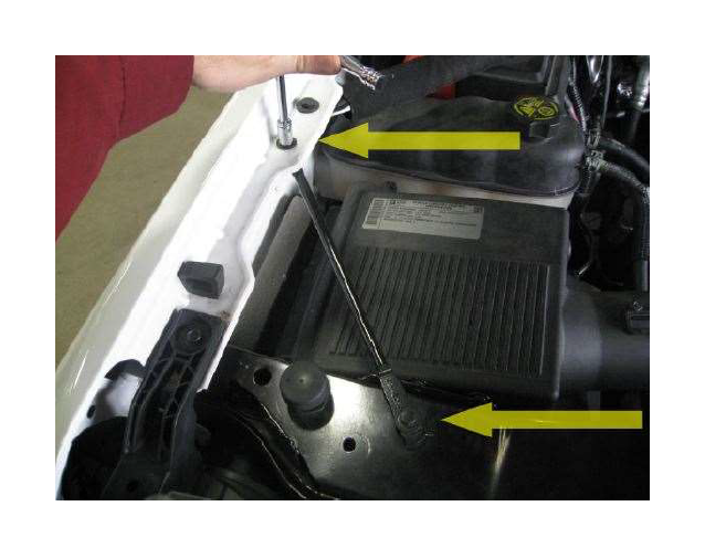
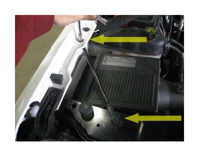
7. Remove the fender to front core support brace. It is held in by 2 bolts (10mm socket).
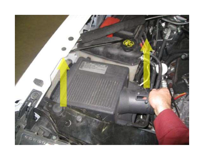
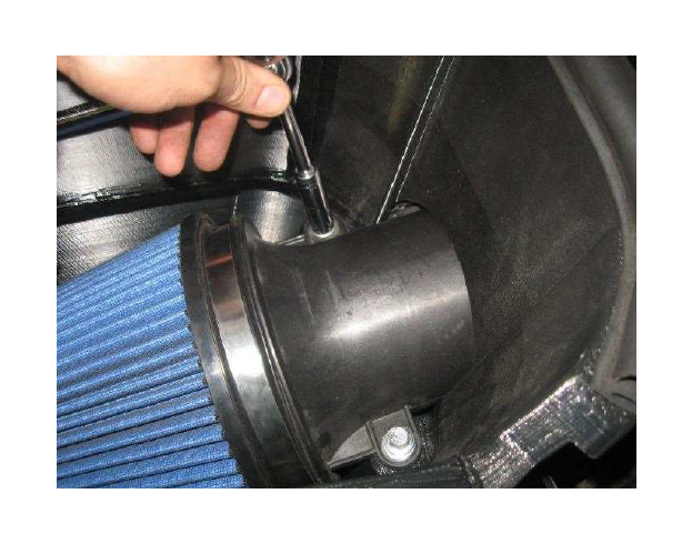
8. Remove the factory air box as an assembly from the vehicle. It is retained by 3 rubber grommets. Pull up and out with some force from the vehicle.
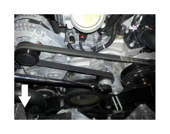
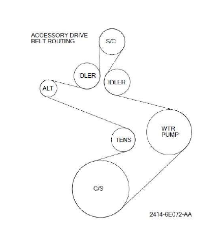
9. Release the accessory drive belt by rotating the tensioner counter clockwise with a ½ inch breaker bar, slip the belt off the alternator pulley and remove the belt completely.
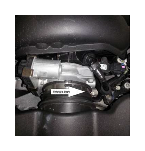
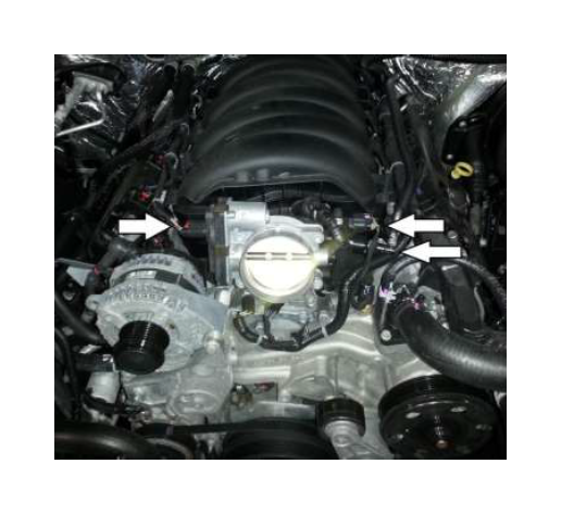
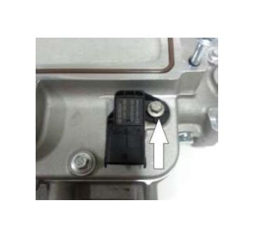
10. Disconnect the throttle body (pull locking tab outward then depress connector), MAP sensor (Pull tab sideways then depress connector) and the vapor management valve wiring harnesses pull locking tab outward then depress connector).
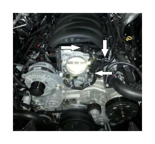
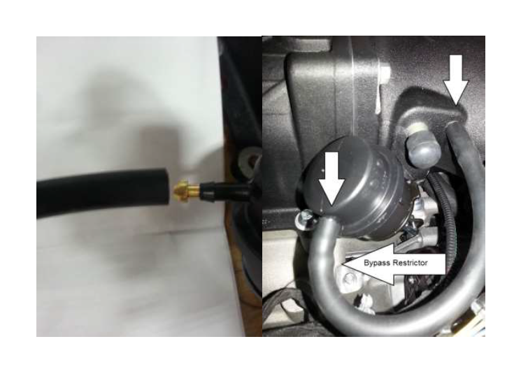
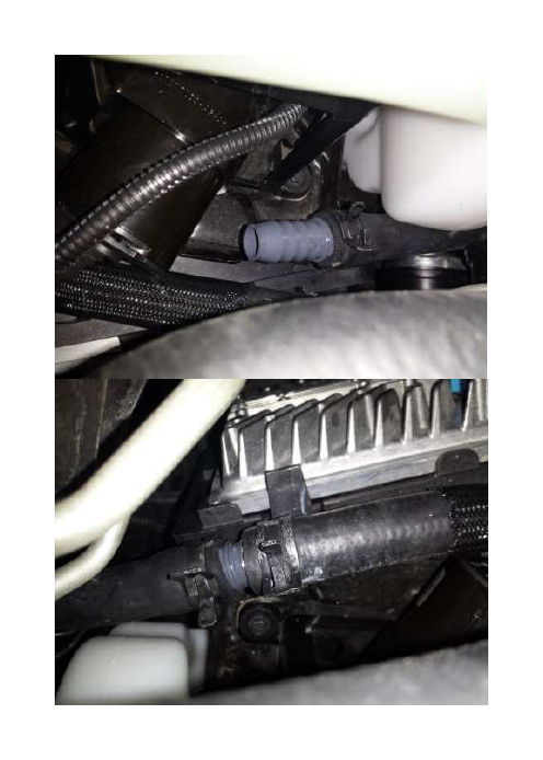
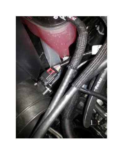
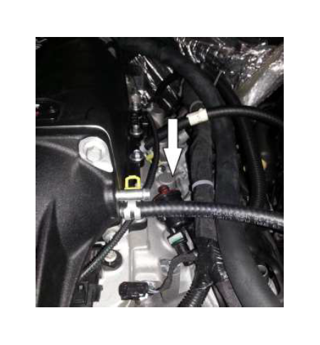
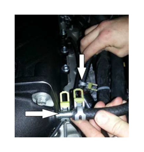
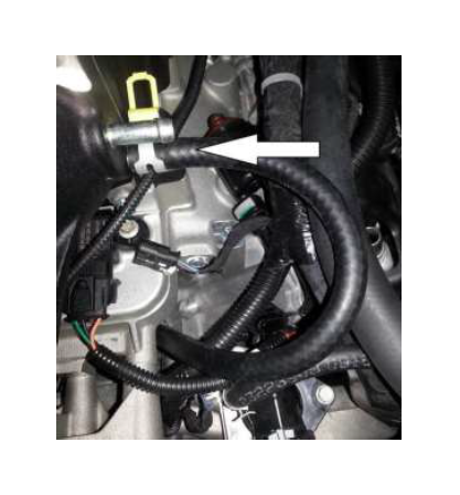
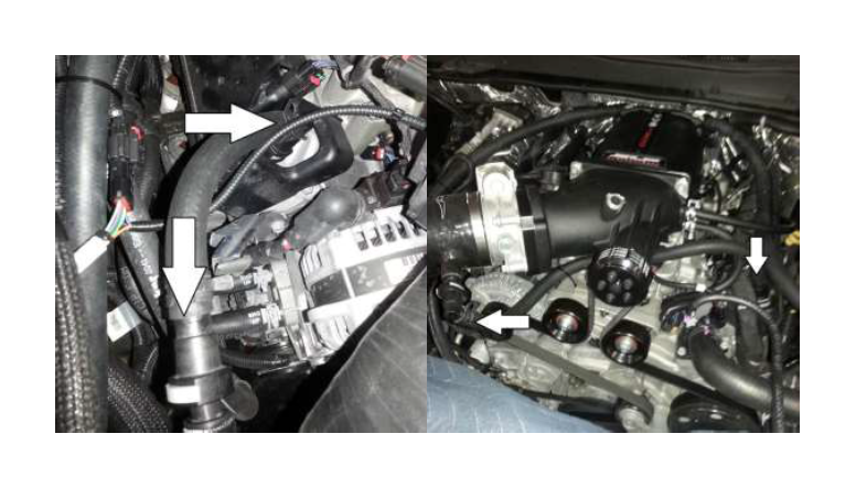
11. Disconnect the three (3) SAE quick connect fittings shown below.
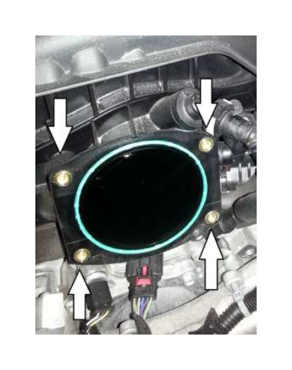
12. Remove the four (4) bolts (10mm socket) holding the throttle body to the intake. Using a pick tool remove the stock throttle body O-ring. Place the throttle body, the bolts and the O-ring aside as they will be reused.
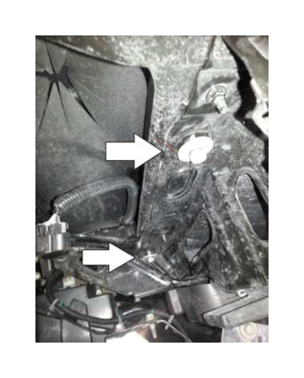
13. Remove the 2 studs and the 2 bolts securing the sounds deadening cover to the intake. Note: the cover will not be removed until the intake manifold is removed.

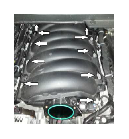
14. Remove the 10 manifold bolts (10mm socket) along the cylinder heads. Note: there is a cutout in the plastic cover at each location. (It may be easier to remove each bolts from the locking sleeve in the intake manifold before pulling it out the manifold.)
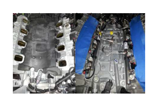
15. Pull the intake upwards and out towards the front of the vehicle. Leave the plastic cover on the vehicle as the intake manifold slides forward.
16. Once the intake manifold is removed pull the plastic cover slightly forward and remove the clips connecting the wiring harnesses on the back of the cover. The cover should then slide out.
17. Remove the isolator that was below the intake manifold. Cover the intake ports with tape to keep debris from falling into the cylinders and causing damage.
SECTION B – MODIFICATIONS
The following section will guide you through the required modifications of existing components and build up of the assemblies used to complete the installation.
PCV Modification
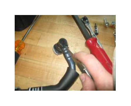
1. Using a knife, carefully cut the tubing to remove a 90° SAE fittings and straight SAE fittings from the stock PCV lines.
2. Using a sharp knife cut piece of 3/8” hose (2414SC-6758) to a length of 7.5 inches. Connect 1 takeoff 90° SAE fitting to one and a straight to the other using two (2) ½ inch constant tension clamp (2UTG7)
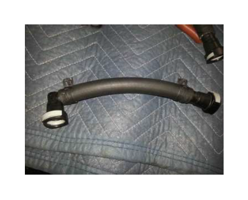
3. Cut another section of bulk 3/8” hose (2414SC-6758) to a length of 27 inches. Connect the fittings using two (2) constant tension clamp (2UTG7).
SECTION C – SUB ASSEMBLY
Intake Manifold Assembly
1. Remove the Fuel Charging Assembly (2414-9H487) from the packaging. Carefully place it onto a clean and sturdy work area-.
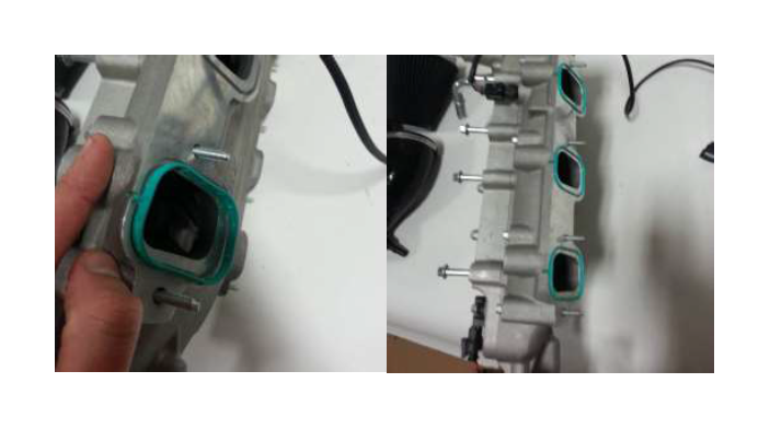
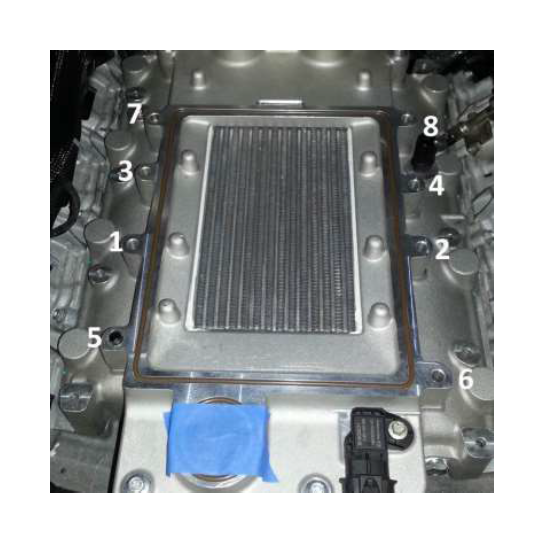
2. Take the 8 supplied GM gaskets (12626354), align them with the cutout feature in the intake manifold (2414-9H487). Push them into place.
3. Apply some o-ring lubricant onto the new 3 Bar TMAP Sensor (BV6Z-9F479) and install into the front of the intake manifold. Install the M6x16 fastener (W500213). These can be found in Hardware Kit B (2414-TVSHWKB). Torque to 10 Nm.
4. Connect the TMAP jumper harness 2414-12A690 to the TMAP. It can be found in hardware kit E (2414-TVSHWKE).
5. Connect the MAF extension harness (2414-12B579W) from hardware kit E (2414-TVSHWKE) to the charge air temperature sensor.
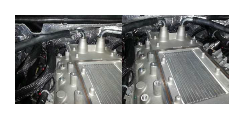
6. Install the supercharger sealing gasket (R07060166) as well as the supercharger bypass gasket (R07060183) into the machined grooves on the upper intake. These can be found in Hardware Kit B (2414-TVSHWKB). Note: Use grease or Vaseline to hold the O-ring in place if it is lifting up. Care should be taken to avoid “rolling the O-ring” and causing a vacuum leak.
7. Install the FEAD bracket (2414-8B653) to the fuel charging assembly (2414-9H487) using (4) M8 bolts (W704752-S437). Torque to 30Nm.
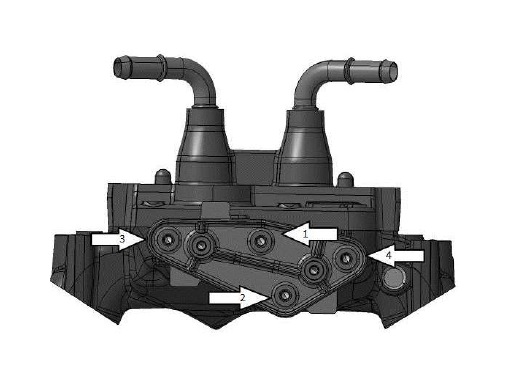
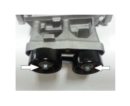
8. Install the idlers (953045) onto the machined bosses and fasten them with M8 bolts (R18020060-00-AA). Torque to 30Nm.
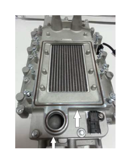
Note – If a vacuum source is required for a boost gauge, there is a plug in the rear
passenger side of the intake manifold. It is a 1/8 NPT thread.
Supercharger Assembly
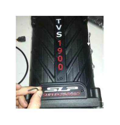
1. Remove the Supercharger (2414-6F066) from the protective packaging and place on a suitable work surface.
2. Install the SLP Badge (010036203) onto the front cover and the TVS1900 Badge (100034001) onto the housing of the supercharger using the four (4) M4x6 fasteners (940706400) found in Hardware Kit B (2414-HWKB). Apply a small amount of blue thread locking compound to the bolts and torque to 3 Nm.
3. Plug the following vacuum port using, the vacuum cap (162611) from hardware kit D (2414- TVSHWKD).
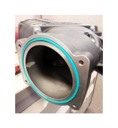
4. Insert the gasket (61436) from hardware kit B (2414-TVSHWKB) into the groove on the supercharger inlet.
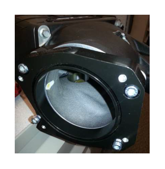
5. Place the throttle body spacer [(2414-9P687) 5.3L or (241462-9P697) 6.2L] as shown on the supercharger inlet. (Note: the position of the cutout on the spacer) Fasten it with 4 (90128A264) bolts, torqueing the bolts to 10Nm.
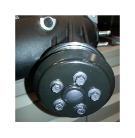
6. Install the supercharger pulley (2414-6K83) on the supercharger using some Loctite on the 5 bolts (W500013-S307) from hardware kit B (2414-TVSHWKB). Torque the bolts to 8-12 Nm. Hint: You may need to torque the supercharger pulley bolts once the FEAD belt is installed.
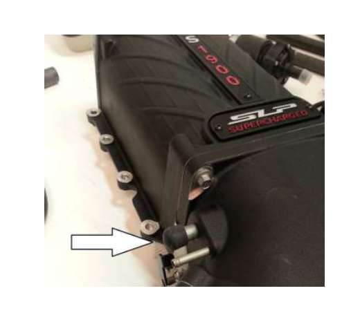
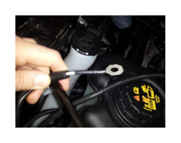
7. Slide the bypass restrictor (ZEX-NS6500M) into the bypass housing. Slide the vacuum line (R18140001-00) over the bypass restrictor and connect the other side to the supercharger as shown.
I/C Pump Wiring Harness
1. Remove the Intercooler Pump Wiring Harness (R07080026) from Hardware Kit E (2414- TVSHWKE).
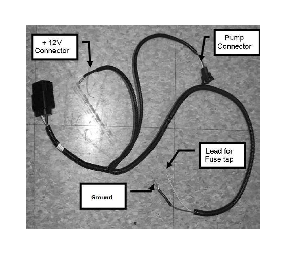
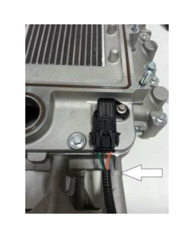
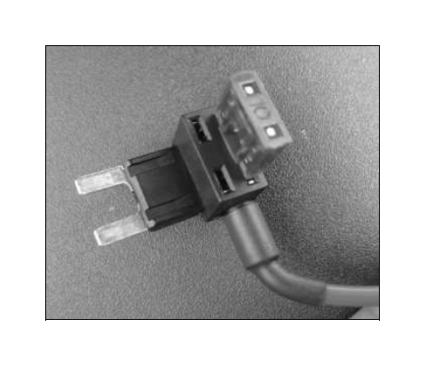
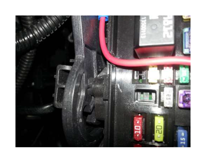
2. Connect and secure the Fuse Tap (Micro2Fusetap) to the lead for the fuse tap on the wire harness indicated above. Use the supplied connector and shrink tube.
3. Install the 10 amp fuse (APT-10A) into the top location of the fuse tap (Fuse tap will look slightly different then what is shown).
4. Cut the eyelet off of the power connector shown. Using the splice connector (020777617) the red 18 gauge wire (6659T54) to the end. These items can be found in hardware kit H (2414- TVSHWKH).
5. Connect the eyelet connector (7113K614) to the other end of the red wire. Use the convolute (FCL1/4) to cover the exposed red wire. These items can be found in hardware kit H (2414- TVSHWKH).
Intercooler Reservoir & Pump Bracket
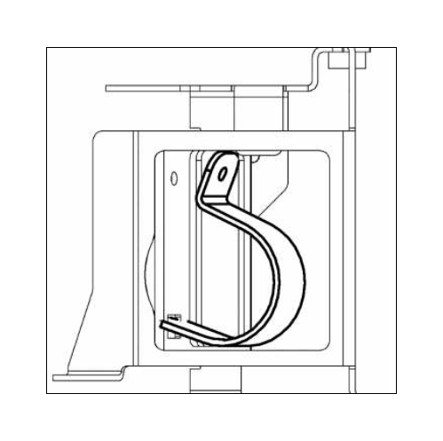
1. Using the Intercooler Pump Bracket (R07070065), hook the bracket onto the Degas Bottle Bracket (R07070059) and leave the pump bracket loose.
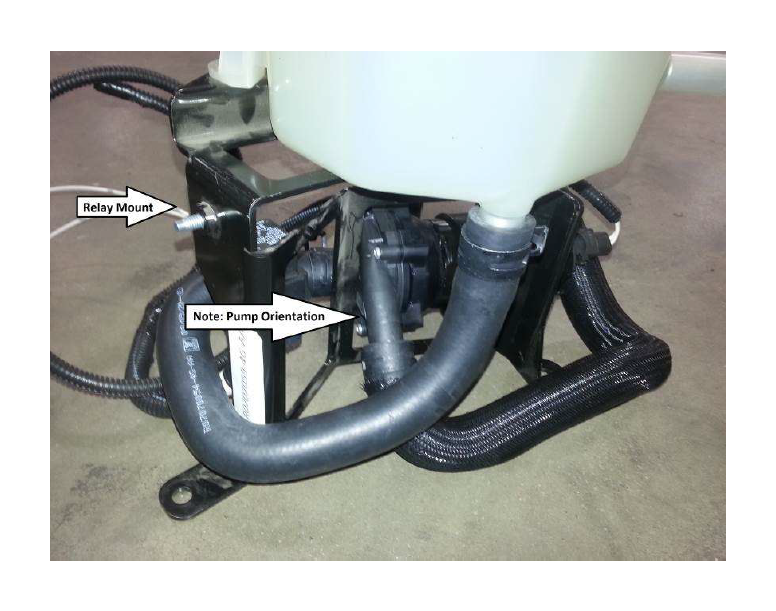
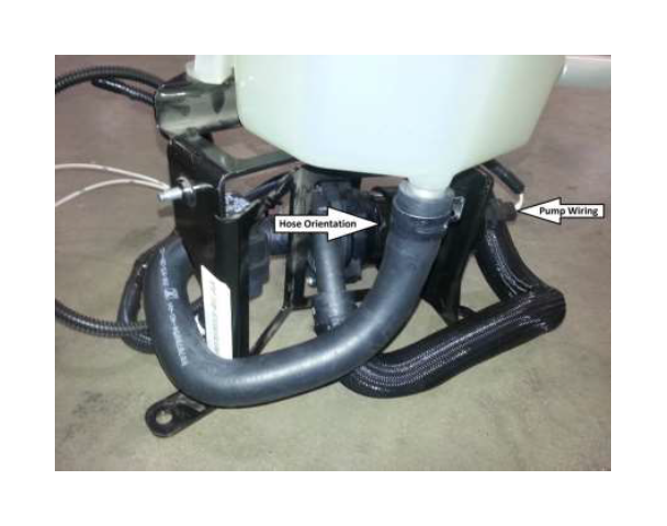
2. Slide the Intercooler Electric Pump (F8YH-8501) into the bracket. Orient the intercooler pump as shown below.
3. Secure the pump in place with (1) M6 x 1.0 x 16 mm bolt (W500213) found in Hardware kit F (2414-TVSHWKF) such that the edge of the bracket is roughly 5mm from the back pump rotor housing. Orient the pump so the outlet is roughly 20 deg from horizontal. Torque to 8 – 12 Nm.
4. Mount the relay of the Intercooler Wiring Harness (R07080026) to the bracket using (1) M6 x 1.0 x 16mm bolt (W500213) found in Hardware kit F (2414-TVSHWKF). Torque to 8 – 12 Nm.
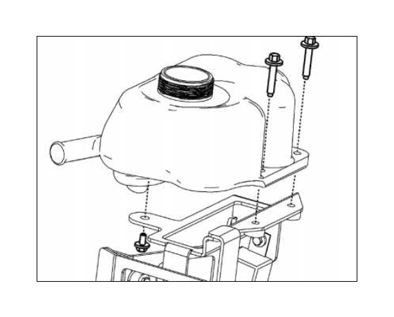
5. Mount the Degas Bottle (R07070007) to the bracket using (2) M6 x 1.0 x 35.5mm bolts (N808429) and (1) M6 cap screw (R18020010) with an M6 washer (R18030002) found in Hardware kit F (2414-TVSHWKF). Torque all fasteners to 8 – 12 Nm.
6. Use the formed hose (R07070054) to connect the outlet of the degas bottle with the inlet of the pump. Use two (2) ¾” constant tension clamps (R07070058) to secure it in place.
7. Connect the Intercooler Pump plug on the wiring harness to the Intercooler Pump.
Air Box Assembly
1. Install the J-Clip (95210A175) as shown into the air box tray.
2. Install the grommet (9600K53) into the air box tray as shown.
3. Place the bulb seal (Part Number 2414-9B624) onto the top of the air box (Part Number 2414- 9A612) and clip into the holes. Trim ends as required.
4. Clean off the fender well, then attach the inlet seal (2414-9F673) as shown.
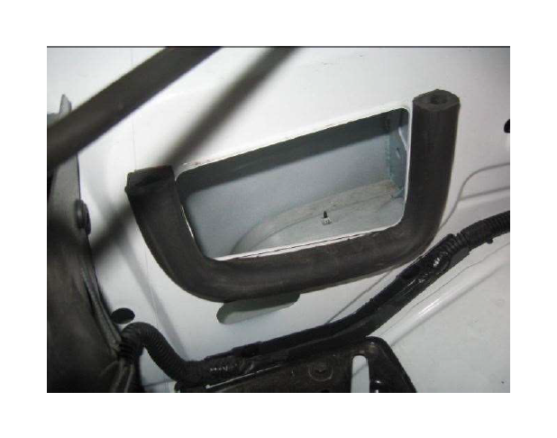
5. Insert the air box assembly into the truck, push down to seat the posts into the grommets.
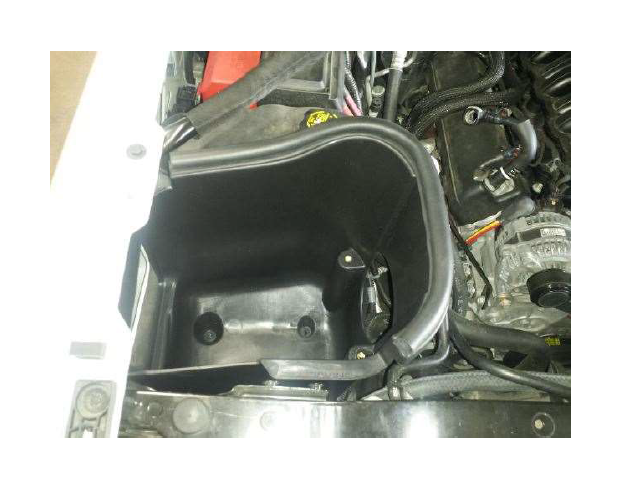
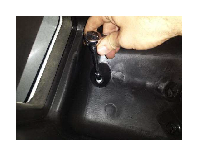
6. Thread and tighten the provided M6 bolt (N605891) into the bottom of the air box, tighten to 10 Nm.
7. Insert the Filter tube (131550-12B579) into the air box tray.
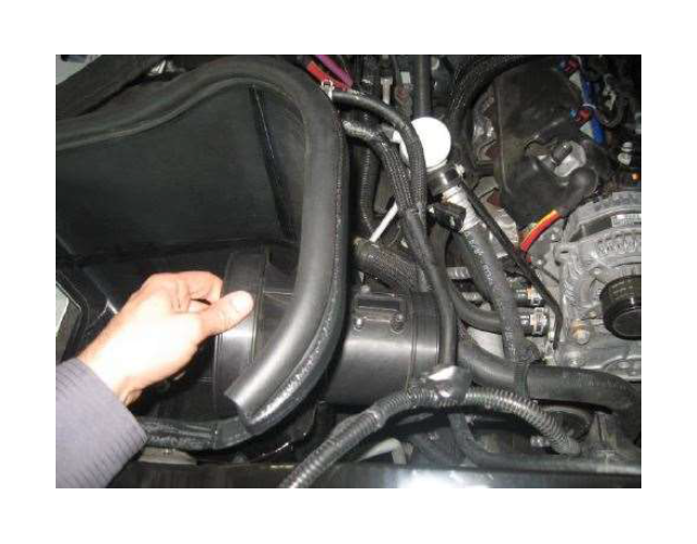
8. Install the air filter (997-494-BLK) onto the filter tube. Make sure the metal rib on the filter points down when the filter tube is oriented as shown. Tighten the filter clamp to 3 Nm.
9. Remove the MAF sensor from the stock airbox assembly (T15 torx). Install the MAF sensor into the Filter tube (2414-12B579), torque the screws to 2Nm.
10. Using the two M8 bolts (W500224), attach the Filter Tube to the Air Box. Tighten to 10Nm.
SECTION D – INSTALLATION
Intercooler Reservoir Assembly Mounting
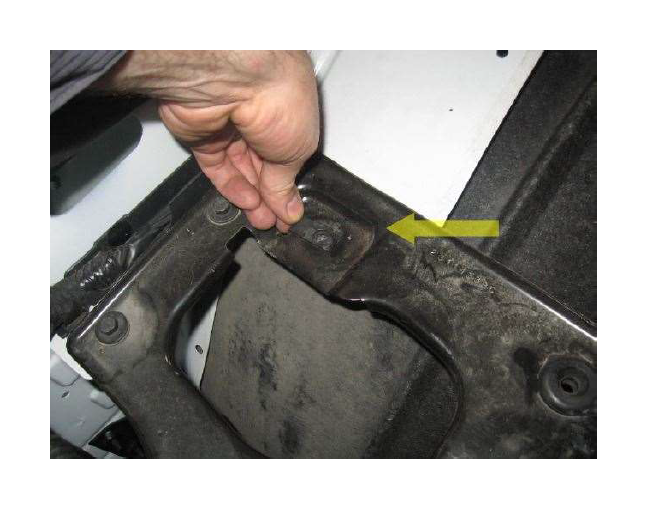
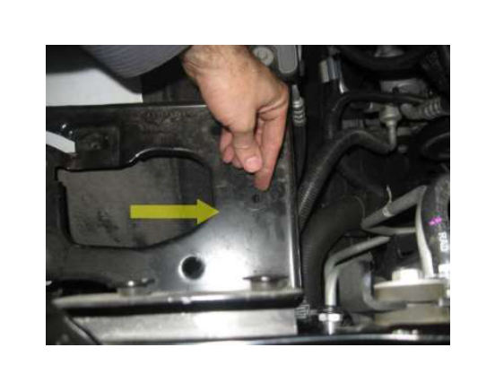
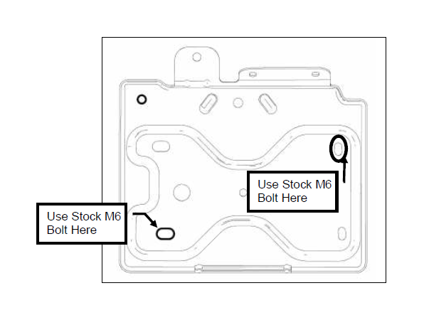
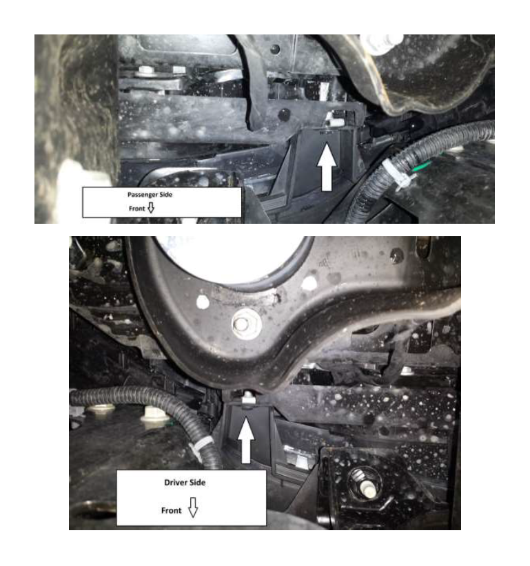
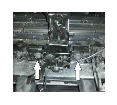
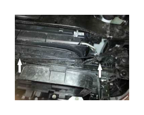
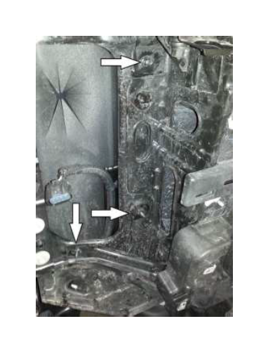
1. Install the intercooler reservoir assembly in the spare battery tray by using the two (2) bolts shown that hold the tray in place. Make sure not to pinch or crush any of the wiring. Torque the stock fasteners to 8 – 12 Nm. Torque the bolt and nut to 20 – 30 Nm.
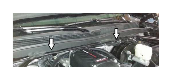
2. Route the power wire along the top of the cowl. Using zip ties or electrical tape, secure the loom to the preexisting loom that runs across the top of the cowl. (Supercharger is not installed at this point.
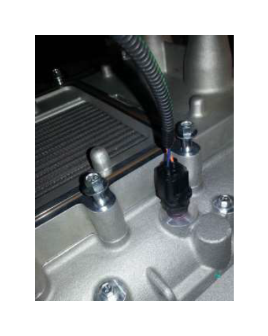
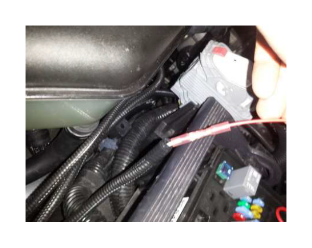
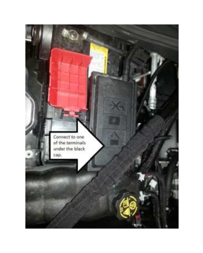
3. Connect the positive eyelet of the wiring harness to the mounting stud next to the battery.
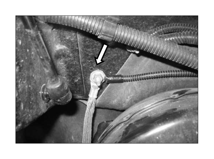
4. Run the long lead of wires from the intercooler wiring harness in between the fuse box and the fender to the cowl area of the truck. Connect the ground eyelet to the grounding post on the cowl wall. Torque the nut to 10 Nm.
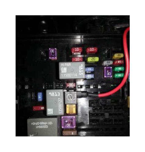
5. Connect the fuse tap to the under hood fuse 34 (ECM).
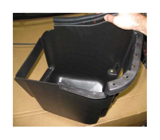
6. Use side cutters or a suitable cutting tool to cut a small opening allow the wire to exit the box without being pinched.
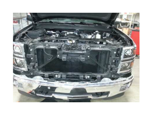
Intercooler Low Temperature Radiator (LTR) Mounting
2014 – 2015 Silverado & Sierra
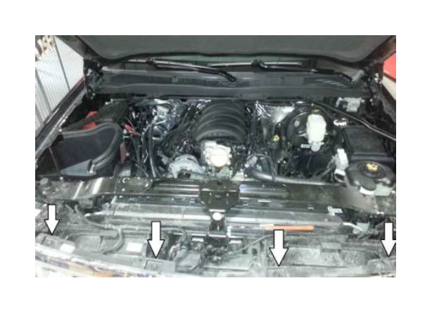
1. Remove the four (4) M6 bolts (10mm socket) holding the grille to the upper front structure.
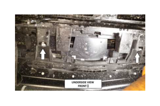
2. Remove the (4) M6 bolts (10mm ratcheting wrench) holding the fascia to the lower core support.
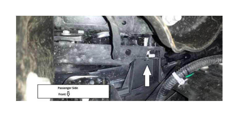
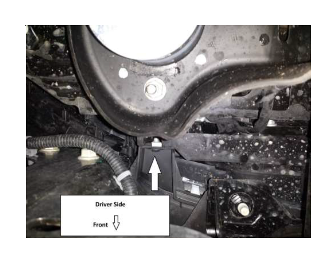
3. Remove the bolts (7mm socket) holding bumper trim piece to the wheel well opening. There are two (2) bolts per side.
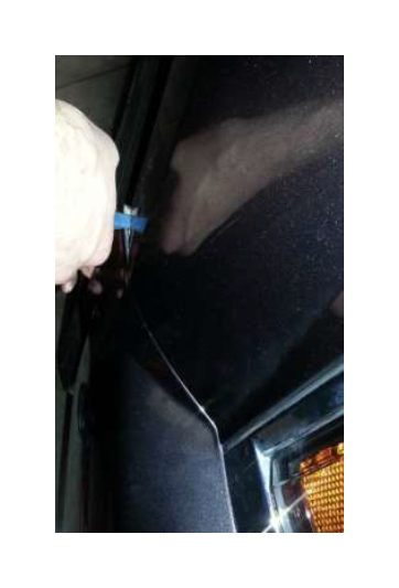
4. Use a plastic trim tool to pry the plastic tabs to remove the grill and front fascia closeout panel away from the vehicle. Note: Make sure vehicle is in a warm location to help prevent the plastic tabs from breaking.
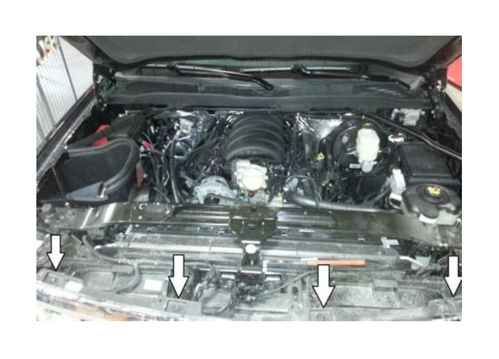
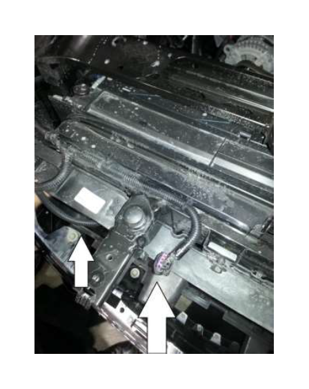
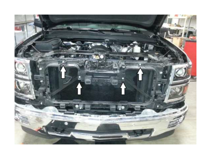
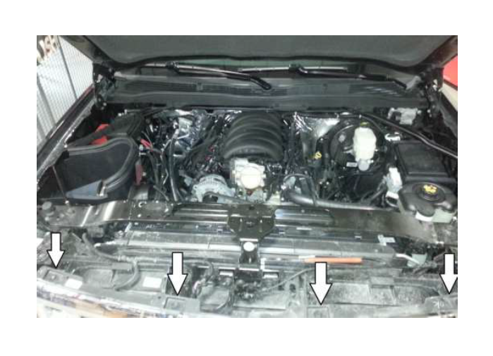
5. Remove the 4 bolts (10mm socket) as shown below.

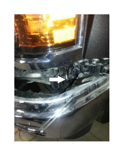
6. Remove the 4 bolts (10mm) holding the driver side headlight in. Repeat this step for the passenger side headlight. Pull the headlight and disconnect it from the electrical harness. Place it aside to protect it from damage.
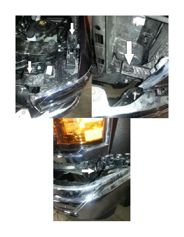
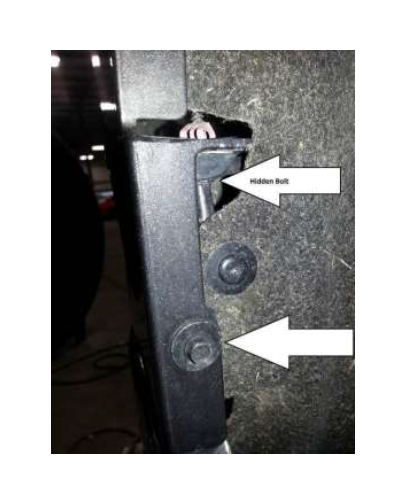
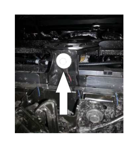
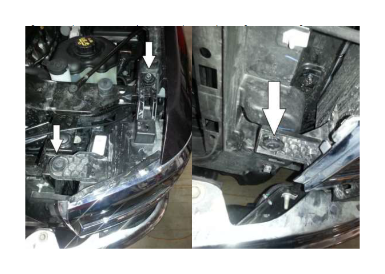
7. Remove the bolt (13mm socket) above the hood release lever.

8. Remove two (2) bolts (13mm socket) from behind the passenger side headlight. Repeat for driver side of vehicle.
9. Remove two (2) bolts holding the hood latch to the core support. Note: Make sure to mark where the latch is located to help with re alignment of the hood.
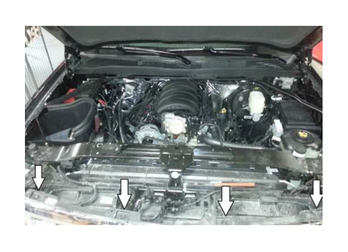
10. Remove the (3) nuts. Repeat this step for the driver’s side.
11. Disconnect the wiring connectors at the hood release lever and the ambient air temperature sensor. Remove the clips holding the wiring harness to the radiator closeout panel.
12. Remove the hood release cable from the clips along the radiator closeout panel.
13. Remove the radiator closeout panel by pulling away from the vehicle. Continue at step 17.
14. Remove the four (4) M6 bolts (10mm socket) holding the grille to the upper front structure.
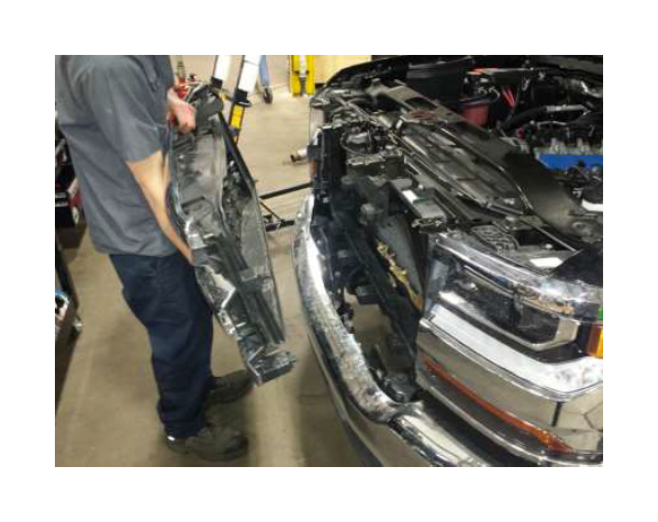
15. Pull the grill outwards making sure to release the clips holding it to the core support.
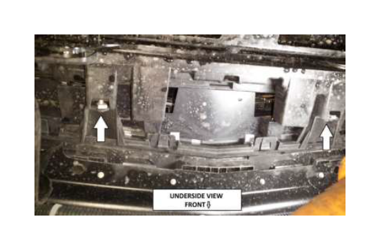
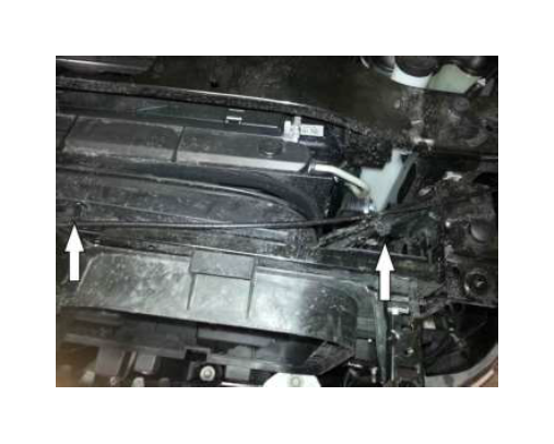
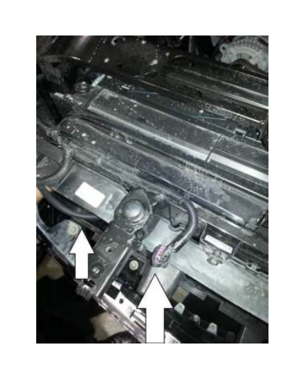
16. Remove both bolts holding the core support together. Push the core support towards the engine to allow for room to install the LTR into position.
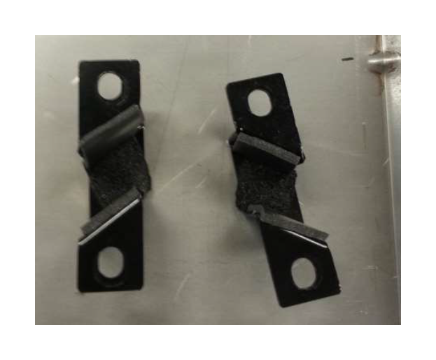
17. Attach the adhesive foam (2414-8K241FOAM) to the three (3) sides of each bracket (2414- 8K244 and 2414-8K245) as shown below.
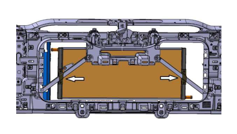
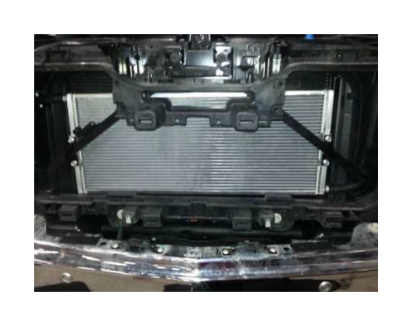
18. Mount the LTR (2414-8K229) using four (4) bolts (90386A108) to attach the brackets (2414- 8K244 and 2414-8K245) to the cross brackets in the grill. Torque to 15 Nm.
19. Using a paint marker, mark the locations that need to be trimmed in order for the coolant hoses to not make contact with the radiator shield.
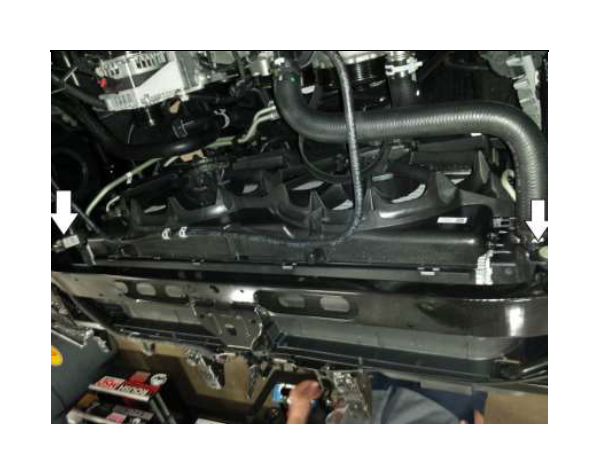
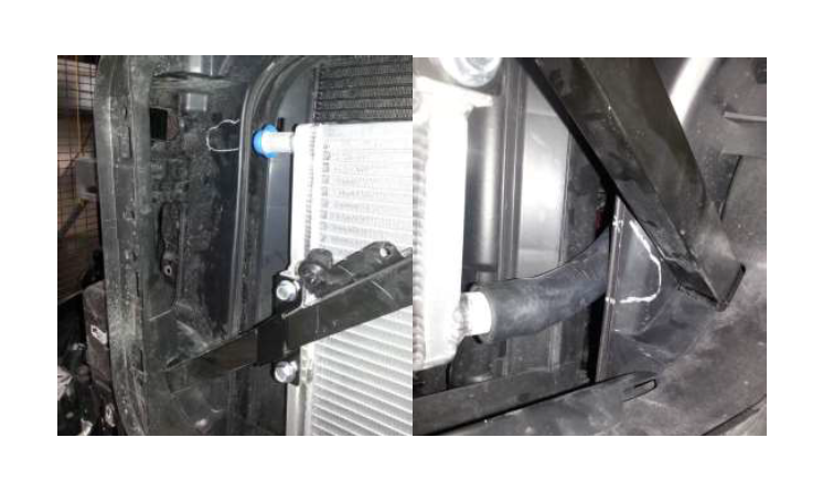
20. Attach the coolant hose (R07070056-4G) using a constant tension clamp (R07070058-4G) to the outlet of the low temp radiator (passenger side). Route the hose through the cut opening into the engine bay. Make sure not to pinch the line when it is in place. Use the protective sleeve (1150- 8K579SLV) on the line in locations that it will rub against any surfaces.
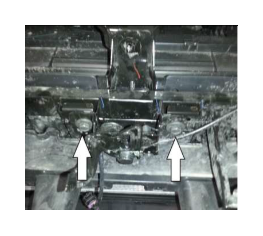
21. Attach the coolant hose (R07070055-4G) using a constant tension clamp (R07070058-4G) to the inlet of the low temp radiator (passenger side). Route the hose in-between the horns on the driver’s side of the vehicle. Make sure not to pinch the line when it is in place.
2014 – 2015 Silverado & Sierra Steps 22-33
22. Reconnect the hood release cable from the clips along the radiator closeout panel.
23. Reconnect the wiring connectors at the hood release lever and the ambient air temperature sensor. Push the clips holding the wiring harness to the radiator closeout panel.
24. Reinstall the (3) nuts. Torque to 10Nm. Repeat this step for the driver’s side.
25. Reinstall two (2) bolts holding the hood latch to the core support. Note: Make sure to relocate the bolt holes to line up with the old location. Torque to 15 Nm.

26. Reinstall two (2) bolts (13mm socket) from behind the passenger side headlight. Torque to 10 Nm. Repeat for driver side of vehicle.
27. Reinstall the bolt (13mm socket) above the hood release lever. Torque to 15Nm.
28. Connect the headlight electrical connectors. Re-install the 4 bolts (10mm) holding the driver side headlight in. Torque to 10 Nm. Repeat this step for the passenger side headlight.
29. Reinstall the 4 bolts (10mm socket) as shown below Torque to 15Nm.
30. Reinstall the grill by lining it up and pushing the tabs back into the locked position.
31. Reinstall the bolts (7mm socket) holding bumper trim piece to the wheel well opening. There are 2 bolts per side. Torque to 3 Nm.

32. Reinstall the four (4) M6 bolts (10mm socket) holding the grille to the upper front structure. Torque to 10 Nm
33. Reinstall the (4) M6 bolts (10mm ratcheting wrench) holding the fascia to the lower core support. Torque to 10 Nm. Continue at step 35.
2016 Silverado & Sierra
34. Reinstall the four (4) M6 bolts (10mm socket) holding the grille to the upper front structure. Torque to 10 Nm
35. Connect the intercooler hose to the hose routing out of the degas bottle using the ¾” X ¾ hose adaptor (28605) using two (2) constant tension clamps (CT19X12-BO).
Intake Manifold and Supercharger
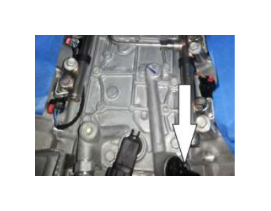
36. Connect the piece (15 inches) of bulk VMV line (2414SC-6758) to the port below the intake manifold. Use a constant tension clamp (7329K11) to secure it. It is easier to connect it now before the intake manifold is attached.
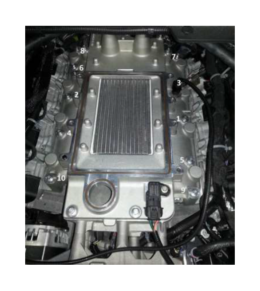
37. Remove the tape from the cylinder heads. Carefully place the intake manifold assembly (with gaskets) down onto the cylinder heads. Be careful not to damage any sealing surfaces or gaskets during this step. Fasten the intake using ten (10) M6 x 1.0 x 74.5mm bolts (N807072- S437). These can be found in Hardware Kit B (2414-TVSHWKB). Torque to 8 – 12 Nm in the sequence shown.
38. Connect the LTR Outlet by routing the hose along the stock heater lines to the passenger side intercooler fitting. Use the protective sleeve (1150-8K579SLV) from the hardware kit H (2414- TVSHWKH) on both the upper cooling system hoses. Secure using one (1) ¾” constant tension clamp (R07070058-4G) found in hardware kit D (2414-TVSHWKD). Connect the degas bottle inlet to the driver side intercooler fitting by using the CAC Outlet to Degas Inlet Hose (R07070057). Secure the hose using two (2) ¾” constant tension clamps (R07070058-4G).
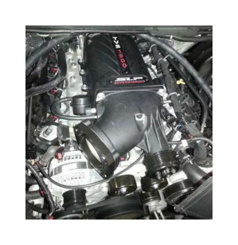
39. Place the supercharger (2414-6F066) onto the intake manifold and secure using eight (8) M8 x 1.25 x 84mm bolts (11116111). Torque to 20 – 30 Nm in the sequence shown.
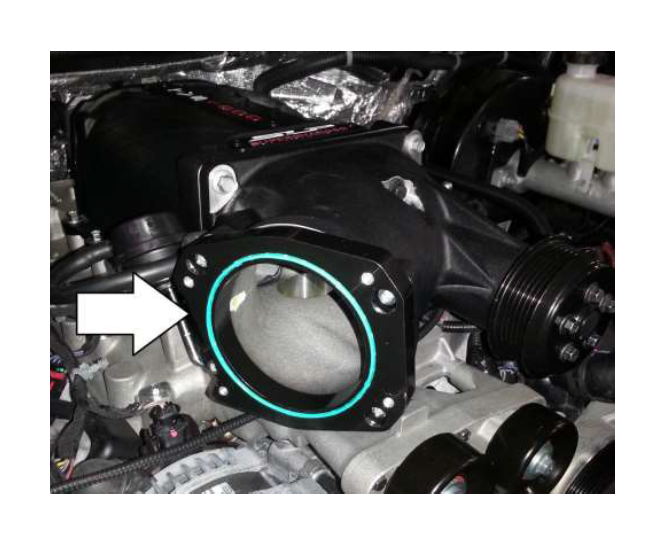
40. Install the takeoff throttle body O-ring onto the throttle body spacer. Then install the takeoff throttle body on the throttle body spacer. Torque to 10 Nm.
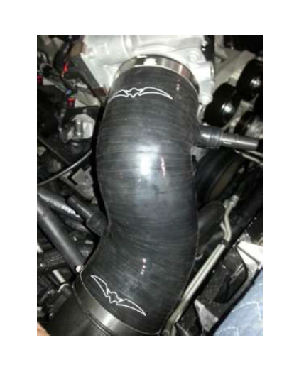
41. Install the clean air tube attaching the throttle body to the MAF tube. [5.3L (2414SC-9B660) 6.2L (2414SC62-9B660)] Torque the clamps to 3 Nm.
42. Connect the MAF jumper harness (2414-12B579W) to the trucks MAF harness and then connect the harness to the MAF. Make sure the harness is ran underneath the supercharger.
43. Remove the VMV solenoid from the stock intake manifold and attach it to the stock line running up the side of the driver’s side valve cover. Re attach the stock electrical connector.
44. Using a piece of the supplied 3/8” line, 18 inches (2414SC-6758), attach it to the solenoids using the constant tension clamp (7329K11) on both sides and route it to the top port on the supercharger.
45. Connect the other piece of bulk 3/8” line that was already connected to the port below the intake manifold to top of the supercharger port using a constant tension clamp (7329K11) from hardware kit H (2414-TVSHWKH).
46. Route the new serpentine belt (K060878) as shown below. Use a ½” drive breaker bar to release tension to install the belt.
47. The PCV hoses that where already modified can now be installed on the vehicle as shown. The short hose is for the passenger side while the long hose travels under the supercharger to the driver’s side as shown.
29. Reinstall the fender to radiator core support bar (10mm socket).
30. Reinstall the front grill and radiator trim cover by reinstalling the push clips.
30. Reinstall the battery connections. Connect the positive cable to the battery first then connect the negative cable.
31. Inspect all underhood wiring harnesses for potential interference issues. Use zip ties to safely position the harness away from any areas of concern.
32. Fill the intercooler system through the degas bottle. The coolant should be approximately one inch below the top of the cap. Install the degas bottle cap (9C3Z-8101) and tighten when full.
Vehicle Reprogramming
Follow the SCT instructions on pages 9 – 14.
Final Assembly
Important: The coolant system can trap a large amount of air. It is very important to verify that the air is purged and that coolant is flowing properly through the systems. SLP recommends vacuum filling the system to properly evacuate the trapped air.
1. Inspect all under hood wiring harnesses for potential interference issues. Use zip ties to safely position the harness away from any areas of concern. Ensure the supercharger bypass has adequate clearance around the actuator.
2. Once the PCM has been successfully re-calibrated, start the engine and check for unusual noises, dash service lights, and unusual operation. If problems are detected, immediately stop the engine or vehicle, diagnose and repair the problem.
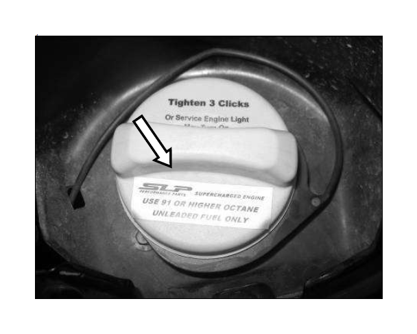
3. Place the Premium Fuel Only Decal (0102040127) beneath the fuel fill cap or on the fill cap itself. With the supercharger system installed, the vehicle is no longer calibrated to run E85 or lower octane fuel. PREMIUM FUEL ONLY is REQUIRED. (Sticker not included with Tuner Kit)
4. Install the Premium Fuel Only – Do not use E85 sticker (R07110005) over the sticker on the fuel door. (Sticker not included with Tuner Kit).

5. Keep your SCT device in a safe location. (the glove box). If you are a retail shop installing this kit, please ensure the end customer gets this device. Each unit is married to the vehicle to which it is flashed and they need to be kept together for any future customer needs.
6. Congratulations, you can now go enjoy your new SLP Supercharged Truck/SUV!!!