FREE 1 to 3-Day Delivery on Orders $149+ Details
How to Install ReadyLIFT 6.5 in. Off Road Lift Kit on your Sierra
***Important*** Check kit contents with Bill of Materials to ensure that all parts are included prior to starting installation. Kit components and hardware are of high grade and specification, do not substitute or modify components or hardware. Contact ReadyLIFT® Suspension customer service with any questions that you may have.
***Important*** Read and study this manual prior to installation, and familiarize yourself with the kit components and procedures. If you are not confident in your abilities or tools, do not perform the installation and refer to one of our Pro-Grade Installers.
1. Park the vehicle on a clean, flat surface and block the rear wheels for safety. Engage the parking brake.
2. Record stock vehicle ride height measurements on both the front and the rear, this will provide and guideline on vehicle rake and lift height. Measure from the center of the wheel up to the bottom edge of the fender well opening and record on chart provided on page 2.
3. Disconnect the vehicle power source at the ground terminal on the battery.
***2014 and newer models equipped with EPAS (Electronic Power Assist Steering), disconnect the power steering control module connector to avoid arching of the contacts in the internal power relay from a hammer blow or impact wrench.***
4. Lock Steering Wheel in straight forward position with the column lock or steering wheel locking device.
5. Raise the front of the vehicle and support with jack stands at each frame rail behind the lower control arms.
6. Remove the front wheels.
7. Remove all factory skid plate and hardware.
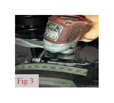
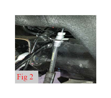
8. Remove the brake line bracket from the frame, and the upper control arm and steering knuckle. Unclip the abs wire from the brake line bracket. (Fig 1, 2, 3)
9. Remove the brake caliper/bracket assembly from the knuckle. Hang the caliper out of the way using a S-Hook or suitable strap. Do Not let the caliper hang by the brake hose. (Fig 4)
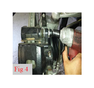
Repeat for both driver and passenger side
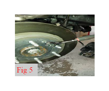
10. Remove the brake rotor bolt and then remove rotor from hub. (Fig 5)
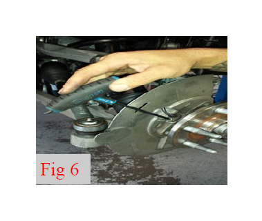
11. Remove the ABS Sensor and Line from the steering knuckle. Hang ABS line out of the way along with brake caliper. (Fig 6)
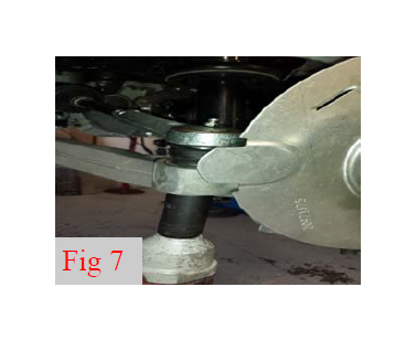
12. Remove the tie rod ends from the steering knuckles. Strike the tie rod boss with a dead blow hammer to break the taper loose. (Fig 7)
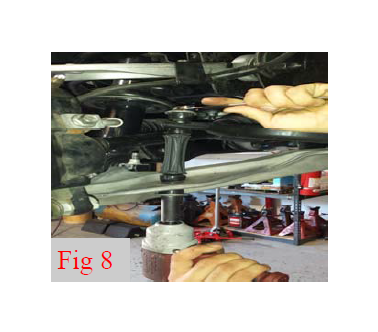
13. Remove the sway bar end links from the sway bar and the lower control arms. (Fig 8)
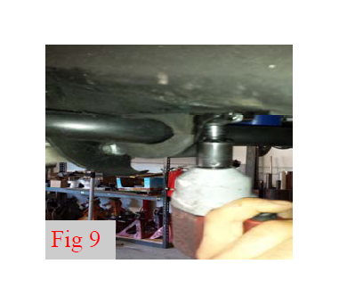
14. Remove the four sway bar mounting bolts. Remove the sway bar from the vehicle noting direction of sway bar in relationship to the vehicle. (Fig 9)
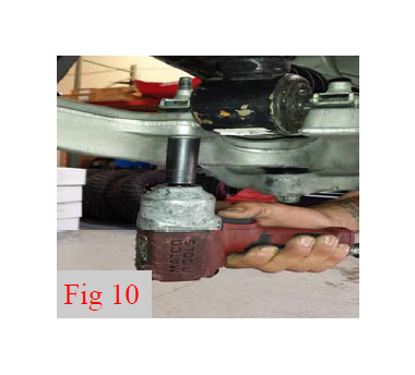
15. Remove the bolts from the strut to lower control arm. (Fig 10)
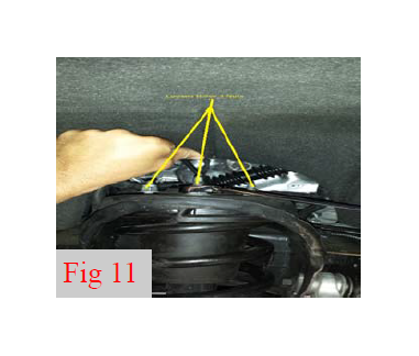
16. Remove the upper strut nuts and remove strut from vehicle. (Fig 11)
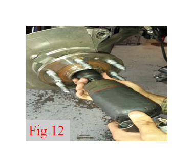
17. Remove the hub dust cap (Some factory hubs do not have dust caps) to expose the axle shaft nut. Remove the axle shaft nut. (Fig 12)
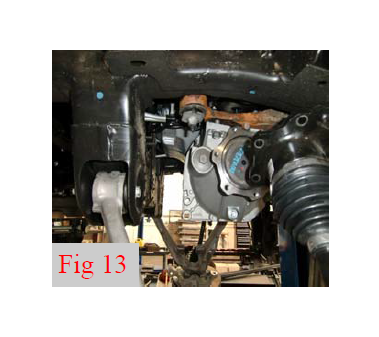
18. Remove the bolts that attach the CV axle to the differential housing. Remove CV axle assembly from the vehicle. (Fig 13)
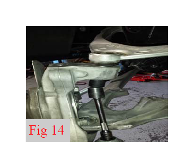
19. Loosen but do not remove the upper and lower ball joint nuts. Strike the ball joint boss on the knuckle with a dead blow hammer to dislodge the taper. Remove knuckle. (Fig 14)
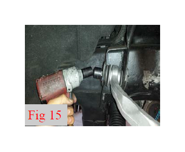
20. Remove the upper control arm cam bolts from the frame and remove the upper control arms from the vehicle. Mark cam bolt and hardware for install later. (Fig 15)
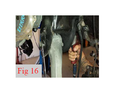
21. Remove the lower control arm mounting bolts and remove the lower control arms from the frame. **Note** retain factory taper washer behind nut. This will be reused later. (Fig 16)
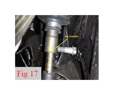
***Rotating the steering wheel while disconnected from the vehicle rack & pinion may cause damage to the steering column and / or internal clock spring.***
22. Remove the pinch bolt that connects the intermediate shaft to the rack and pinion. Remove the intermediate shaft from the rack and pinion unit. (Fig 17)
***Use extra caution not to damage any wiring or electronic components. Do not drop, hit, or tamper with the rack and pinion unit. Keep the rack and pinion unit in a safe and secure location until it is time to re-install.***
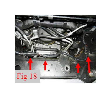
23. Disconnect the wiring harness and plugs from the Front cross member (Fig 18)
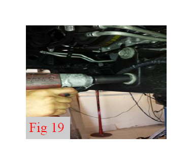
24. Support the rack and pinion unit with a jack or suitable device, remove the four mounting bolts that attach the rack and pinion to the frame. Remove the rack and pinion assembly from the vehicle. (Fig 19)
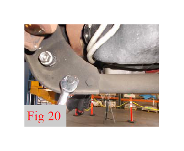
25. Remove the four bolts that attach the OEM cross member to the frame at the rear lower control arm pocket using 18mm. Remove the cross member from the vehicle and discard all. (Fig 20)
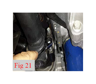
26. Remove the driveshaft mounting bolts and disconnect the driveshaft from the differential. Allow the driveshaft to rest out of the way. (Fig 21
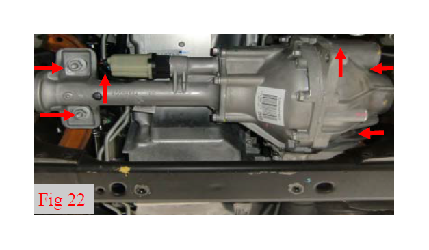
27. Disconnect the actuator connector, harness, and vent tube from the front differential. (Fig 22)
***Warning...The front differential is heavy and awkward. It is best removed by two people, and / or a suitable jacking device.***
27. Utilizing an appropriate jack, support the differential housing. Remove the front differential. (Fig 22)
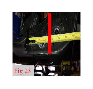
28. Locate the rear control arm pocket on drivers and passenger sides and measure 3 3/8” from the inner edge of the pockets out towards the frame / outside of truck. Mark a vertical cut line on both sides of the frame pocket and connect these lines up and over the top side. (Fig 23)
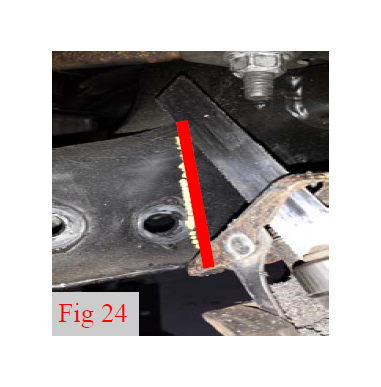
29. Using a cutting tool, cut along the line from to remove this section of cross member support from the control arm pocket. Round off the bottom corners and sand any sharp edges. Paint any exposed metal surface with quality rust preventative paint. (Fig 24)
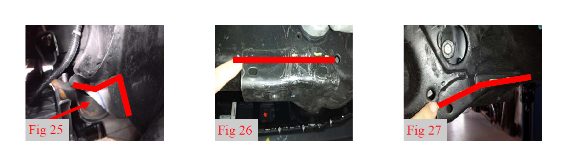
30. Using a cutting tool, cut the frame on the upper front driver side differential mount as marked. This is cut for clearance of the steering shaft extension u-joint. (Fig 25)
31. Using a cutting tool, cut the factory skid plate mounting bracket from the frame. The Cut line should parallel the front cross member profile. Sand, clean and paint exposed metal surface. (Fig 26, 27)
32. Using a cutting tool, trim the lower plates across the factory welds from both the upper control arm pockets on drivers and passenger sides. Sand and smooth all cut areas flush with the frame and upper control arm pockets. (Fig 28)
***DO NOT CUT INTO THE FRAME RAILS***
33. Using a suitable cutting tool, cut the upper control arm bump stop out completely from the upper control arm mounting pockets as shown. (Fig 29
34. The upper control arm frame pockets must be clean and free of excess material in order to accept the upper control arm drop brackets. Check for proper fitment at this time. It may be necessary to slightly “spread” the pockets for fitment. Use a heavy hammer to strike and open up the pockets. (Fig 30)
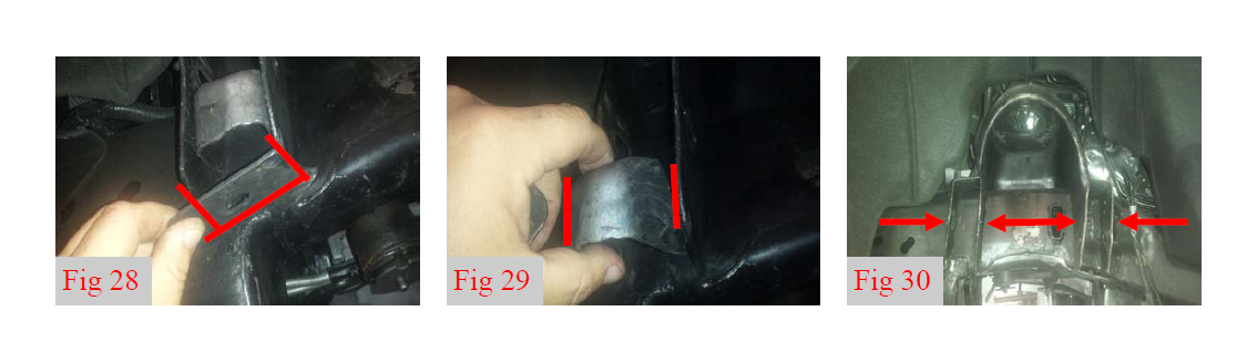
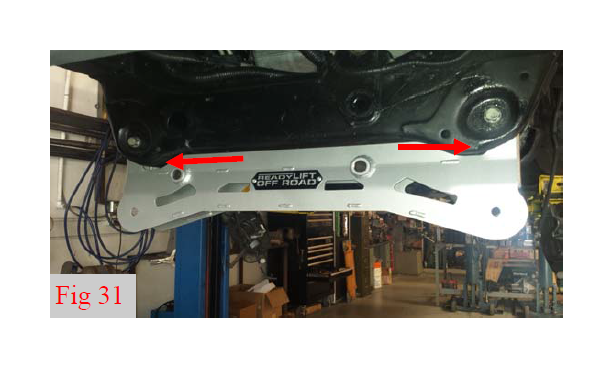
35. Front Cross Member Fitment. It may be necessary to slightly remove some material at the corners of the control arm pockets front and back in order to fit the new front cross member into the frame. It may also be necessary to “spread” open the pockets. Check the front cross member for fitment. Use a suitable cutting tool to remove material for fitment. Use a large hammer to strike the factory frame pocket tabs to “spread” them open to aid in cross member installation. (Fig 31)
***Rack and Pinion Clearance Instructions***
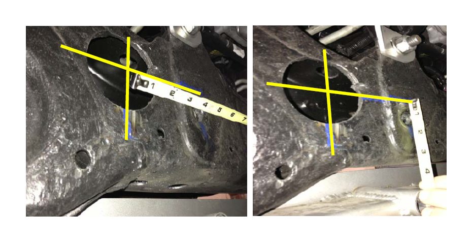
36. You will need to Drill / Cut a hole to make clearance for lowering the Rack and Pinion.
Measure from the lower mounting hole for the rack and pinion on the driver side 3 3/4” from the center of the mounting hole to the left or outside of the driver side of the frame and make a vertical line. Now measure from the same lower mounting hole 7/8” and make a horizontal line. Where these two lines intersect will be the center of the 3” hole. Use an appropriate metal cutting 3” hole saw to drill out the hole in the frame.
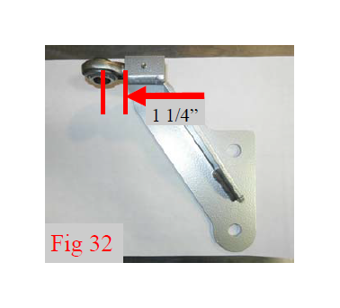
37. Locate the steering extension support bracket. Install ¾” rod end from bag 48-3303 into extension 1 1/4” from the face of threaded insert to center of the ball. Secure in the horizontal position with set screw. (Fig 32)
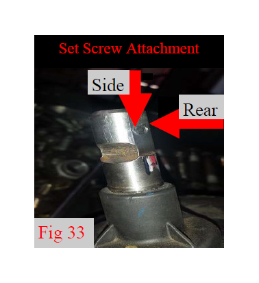
38. Locate the steering u-joint and steering extension shaft from bag 48-3303. Install steering shaft extension onto the factory rack and pinion shaft noting the location of the set screws for the new u-joint. Make sure the notch is in the same line as the factory notch on the rack and pinion shaft. (Fig 33)
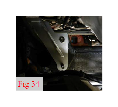
39. Install steering extension drop bracket assembly into the frame using one of the factory bolts from the rack and pinion and the supplied M16 flat washer and M16 nut from bag 48-3930-1 in the original upper hole. Note: Only install the top hole of the bracket as the lower will be used to install the steering rack. Do not tighten at this time. (Fig 34)
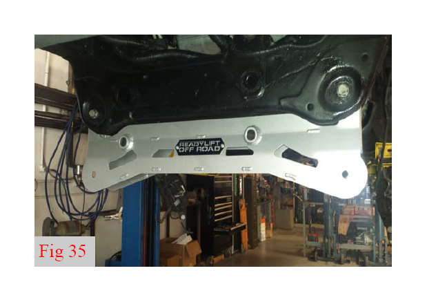
40. Install the front cross member using factory hardware. Insert the bolts from the rear. Make sure tapered factory washer has taper pressing into frame. Do not tighten at this time. (Fig 35)
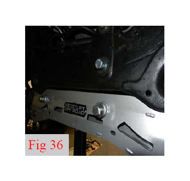
41. Install the factory rack and pinion unit lower mounting points with the previously installed u-joint and steering extension shaft assembly to the front cross member and frame using M16 x 170mm bolt and M16 x 6mm thick washer in the driver side hole, and the M12 x 140mm bolt and M12 x 5mm thick washer on passenger side hole from bag 48-3930-1. Do not tighten at this time. (Fig 36)
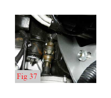
42. As you raise the rack and pinion unit, slide the steering extension shaft and u-joint assembly through the ¾ rod end attached to the support bracket. (Fig 37)
43. Attach the rack and pinion unit upper driver side mounting point to the factory cross member using M16 x 170mm bolt and M16 x 6mm thick washer making sure to pass through steering extension bracket lower mounting hole. Do not tighten at this time. (Fig 36)
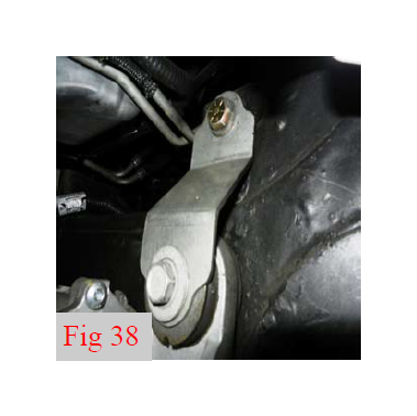
44. Install passenger side rack and pinion drop bracket using factory hardware on the backside of the rack and pinion mounting point and 1/2” x 1” bolt, washers, and c-nut to the original upper passenger side front cross member mount. Do not tighten at this time. (Fig 38)
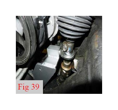
45. Install factory intermediate shaft onto the Readylift steering extension using factory pinch bolt using 11mm socket. Torque to165 inlbs. (Fig 39)
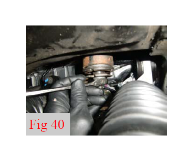
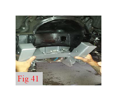
47. Locate and remove the nut from the factory differential hangers. The upper control drop brackets utilize this mount. (Fig 40)
48. Install the upper control arm drop bracket assemblies into the upper control arm frame pockets using the M14 x 80mm bolts, washers, and c-lock nuts from bag 48-3940 and brake line support bracket 48- 3600. The bracket is being used as a washer. Do not tighten at this time. (Fig 41)
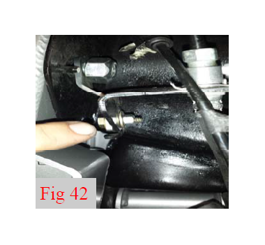
49. Install the front brake line support bracket onto the rear upper control arm drop bracket bolt. (Fig 42)
50. Attach the factory brake line bracket assembly to drop bracket using 1/4” x 3/4” bolt, washers and c-lock nut from bag 48-3960. Do not tighten at this time. (Fig 42)
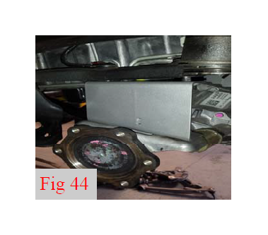
51. Install both the driver and passenger side differential drop brackets onto the existing factory mounts using the factory hardware. Do not tighten at this time. (Fig 43, 44)
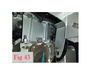
52. Install the differential onto differential drop brackets using 1/2” x 1 3/4” bolts, washers and c-lock nuts on the drivers drop bracket and 9/16” x 1 3/4” bolts, washers and c-lock nuts on the passenger drop bracket from bag 48-3930. ***Make sure to install bolts from the bottom facing up.*** Tighten all differential mounting hardware at this time starting with the top factory hardware, and moving down to the supplied hardware. Torque factory and 1/2” hardware to 95 ft-lbs. Torque 9/16” hardware to 100 ft-lbs. Connect electrical connector and vent tube to the differential. (Fig 43, 44)
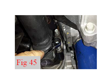
53. Re-attach the front drive shaft to the front differential using factory hardware, add a drop of Loctite. Torque to 18 ft-lbs. (Fig 45)
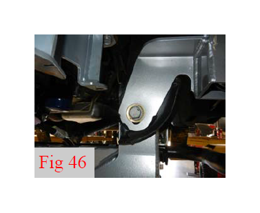
54. Install the Rear Cross Member into the frame pockets using the factory bolt and 5/8” flat washer from bag 48-3900, through upper control arm drop brace and the front cross member, taper washer facing the frame, and factory nut. Do not tighten at this time. (Fig 46)
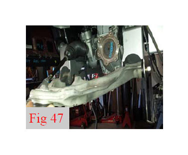
55. Install the factory lower control arms into the front and rear cross members using 5/8” x 4.5” and 5/” x 5.5 bolts, washers and c-lock nuts from bag 48-3900. Do not tighten at this time. (Fig 47)
56. Torque the cross members, upper control arm drops, rack and pinion mounting hardware at this time. Torque the cross member to 150 ft-lbs, upper control arm drops to 100 ft-lbs, Make sure the brake line brackets face straight down after this procedure. Torque the driver side rack and steering extension bracket bolts to 100 ft-lbs, passenger side bolts to 90 ft-lbs.
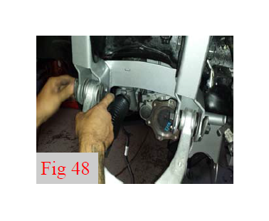
57. Install the factory upper control arms into the upper control arm drop down brackets using the factory cam eccentrics and bolts. Do not tighten at this time. (Fig 48)
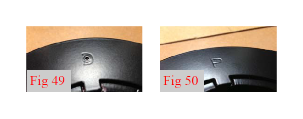
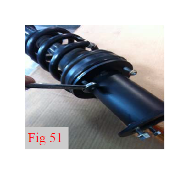
58. Locate and install the strut spacer onto their corresponding struts using supplied factory hardware. D is driver and P is passenger side. (Fig 49, 50, 51)
59. Install the strut assembly onto the frame using supplied 10mm flange nuts. Install the lower control arm to lower strut mount using factory hardware. Torque upper hardware to 30 ft-lbs and lower hardware to 90 ft-lbs.
Repeat for both driver and passenger sides
60. Install the CV Axles to the front differential using factory hardware. Add a drop of Locktite. Torque to 70 ft-lbs.
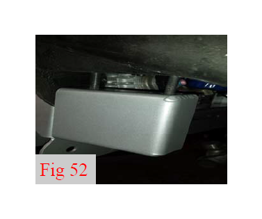
61. Install sway bar drop brackets onto the frame using the factory hardware. Torque to 45 ft-lbs. Attach the sway bar to the bottom of the drop down brackets using the 7/16” x 1 1/2” bolt, washers and clock nuts from bag 48-3934. Torque to 45 ft-lbs. (Fig 52)
62. Install the factory end links onto the sway bar and lower control arm using the factory hardware. Torque to 40 ft-lbs.
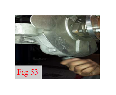
63. Install the factory knuckle to the lower ball joint (while sliding the axle into the hub assembly) using factory hardware. Torque to 110 ft-lbs. Install axle nut and washer. Torque to 150 ft-lbs. (Fig 53)
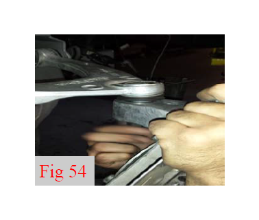
64. Install upper control arm to knuckle using factory hardware. Torque to 85 ft-lbs. (Fig 54)
65. Attach ABS wire to hub assembly using factory hardware. Torque to 5 ft-lbs.
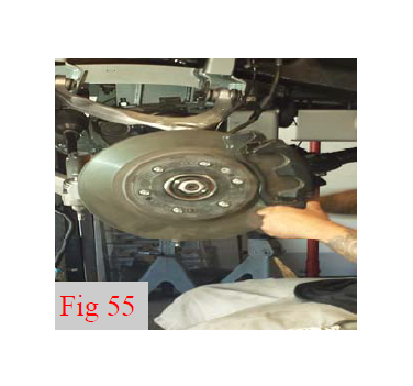
66. Install the factory brake rotor using the factory hardware. Torque to 5 ft-lbs. (Fig 55)
67. Install the factory caliper using the factory hardware. Torque to 100 ft-lbs. (Fig 55)
68. Install brake line brackets onto knuckles and control arms using factory hardware. Clip abs wire back into brake line bracket. Torque to 5 ft-lbs. Torque the brake line bracket to the drop bracket to 20 ftlbs.
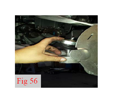
69. Install tie rod end onto knuckle using factory hardware. Torque to 85 ft-lbs. (Fig 56)
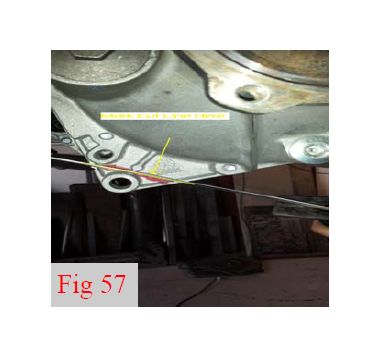
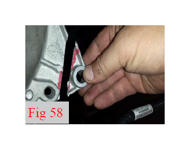
70. Cut the front ear off the differential as shown for skid plate clearance. (Fig 57, 58)
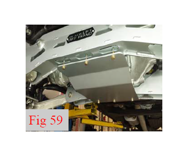
71. Install skid plate using 3/8” x 1” hardware from bag 48-3935. Torque to 45 ft-lbs. (Fig 59)
72. Double check all upper control drop brackets, differential drop brackets, and steering bolts at this time for tightness and proper torque.
73. Install the wheels and lower vehicle to the ground. Torque the lug nuts to the wheel manufactures specs.
74. Jounce the vehicle to settle the suspension. Torque the lower control arm bolts to 150 ft-lbs.
75. Center the upper control arm cam bolts and torque to 120 ft-lbs.
Rear Installation:
1. Block the front wheels and raise the rear of the vehicle. Place jack stands under the frame rails ahead of the spring hangers.
2. Remove the wheels.
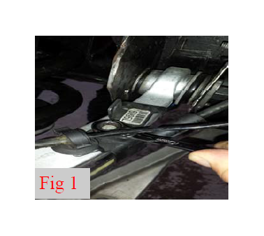
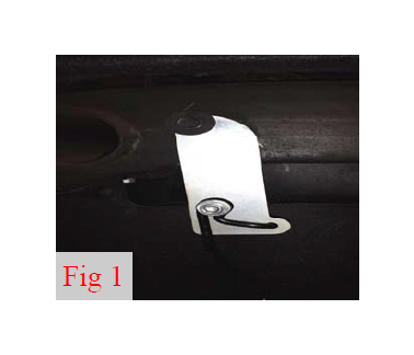
3. Disconnect the factory rear emergency brake line support bracket from the inner frame rail and install rear E-Brake Drop Bracket using 3/8” x 1” bolt, washers, and c-lock nut from bag 48-3960. Torque to 20 ft-lbs. (Fig 1)
4. Unbolt the factory hard line mounting bracket from the top of the frame.
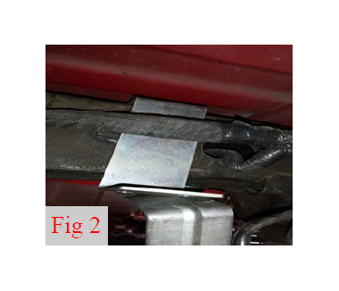
5. Gently pull down on the bracket and hard lines and install brake line drop bracket using the factory bolt to the frame. Attach the factory bracket using 1/4” x 3/4”bolt, washers, and c-lock nut from bag 48-3960. Torque to 10 ft-lbs (Fig 2)
6. Support rear axle with a suitable jack and remove the shocks. Discard shocks as they will not be reused.
7. Disconnect the ABS wires from their points on the frame rails under the bed and bottom of the frame. Disconnect the electrical connectors.
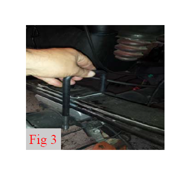
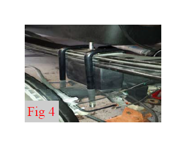
8. Slightly loosen but do not remove the driver side u-bolts. Remove the passenger side u-bolts completely and discard. Lower the axle just enough to remove the factory blocks and install the lift blocks. Locate the passenger side lift block, making sure the tapered end points to the front. Install the lift block on the axle pad aligning the center pin. Raise the axle and the block up to the spring while aligning the center pin. Install the provided u-bolts, washers and nuts. Snug the u-bolt nuts but do not fully tighten at this time. Repeat steps for driver side. (Fig 3, 4)
9. Remove the factory bump stops from the frame. Install bump stop onto extension and frame using M10 x 100mm Allen bolt from bag 48-3960. Torque to 45 ft-lbs.
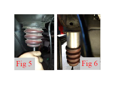
10. Install aftermarket shocks using factory hardware. Torque to 60 ft-lbs. (Fig 5,6)
11. Reconnect the ABS electrical connectors. Pull the ABS wires through the lower frame connector to gain slack for suspension travel and connect onto to the lower frame rail. Make sure there is slack at full droop. Zip tie the excess wire out of the way of suspension components and exhaust.
***Final install and checks***
Recheck that all hardware is of proper torque values and all electrical connections are hooked up. Start vehicle and verify that all dash warning lights are off. Cycle the steering wheel from lock to lock to check for any interference of steering intermediate shaft, steering extension, steering u-joint. wheels, tires, brake lines, hoses, wires, ect and ensure adequate clearance through out the suspension cycle. Adjust as necessary.
*** Due to manufacturer frame variances, if there is any contact between steering extension, ujoint or intermediate shaft, it may be necessary to remove extension from intermediate shaft and ujoint to adjust rod end in to gain clearance.*** If driving vehicle to an alignment shop, adjust toe prior to vehicle operation.
Install all warning tags and decals as directed:
1. Rear view mirror hanging warning card: Hang from rear view mirror to warn driver of vehicle modification.
2. Lifted truck warning decal: Apply decal to the upper left hand corner of the inside of the windshield facing the driver.
Give all installation instructions, warranty information, and all remaining literature to the end user to keep with vehicle records.
Final Checks & Adjustments
Post Installation Warnings: Once the vehicle is lowered to the ground, check all parts which have rubber or urethane components to insure proper torque. Torque wheels to factory specs. Move vehicle backwards and forwards a short distance to allow suspension components to adjust. Turn the front wheels completely left then right and verify adequate tire, wheel, brake line, and ABS wire clearance. Test and inspect steering, brake and suspension components for tightness and proper operation. Inspect brakes hoses and ABS lines for adequate slack at full extension.
***FAILURE TO PERFORM THE POST INSPECTION CHECKS MAY RESULT IN VEHICLE COMPONENT DAMAGE AND/OR PERSONAL INJURY OR DEATH TO THE DRIVER AND/OR OTHERS***
Vehicle Handling Warning: Vehicles with larger tires and wheels will handle differently than stock vehicles. Take time to familiarize yourself with the handling of your vehicle.
Wheel Alignment/Headlamp Adjustment:
It is necessary to have a proper and professional wheel alignment performed by a certified alignment technician. Align the vehicle to factory specifications. It is recommended that your vehicle alignment be checked after any off-road driving. In addition to your vehicle alignment, for your safety and others, it is necessary to check and adjust your vehicle headlamps for proper aim and alignment
Vehicle Re-Torque and Safety Inspection:
Upon completion of all services and adjustments performed on your vehicle, and within 50 miles of driving, check to ensure all fasteners and hardware are properly torqued to specification as noted in the vehicles factory service manual or the torque chart included.
***RECHECK ALL HARDWARE FOR PROPER TORQUE VALUES AFTER 500 MILES, AND THEN PERIODICALLY AT THE EACH SERVICE INTERVAL THERAFTER.***
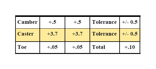
Recommended Alignment Specs