FREE 1 to 3-Day Delivery on Orders $149+ Details
How to Install Air Lift Performance 1000 Air Spring Kit (09-18 RAM 1500) on your Dodge RAM
Installation Time
2 hours
Tools Required
- Hoist or floor jack
- Safety stands
- Safety glasses
- Air compressor or compressed air source
- Spray bottle with dish soap/water solution
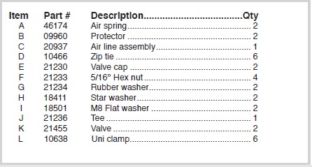
HARDWARE LIST
Installing the Air Lift 1000 System
GETTING STARTED
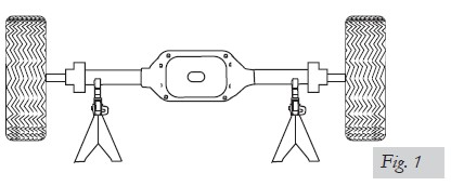
1. Jack up the rear of the vehicle or raise on a hoist. Support the frame with safety stands (Fig. 1).
2. Lower the axle or raise the body of the vehicle until the springs are completely extended (wheels hanging).
OBSERVE TENSION ON BRAKE LINE. DO NOT STRAIN.
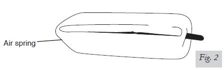
3. Remove the plastic cap from the barbed stem on the end of the air spring. Exhaust the air from the air spring by rolling it up toward the barbed stem. Replace the cap on the stem to hold the flat shape (Fig. 2). Fold air spring into a “hot dog bun” shape.
4. Insert the flattened air spring into the coil spring through the lowest opening with the stem at the top (Fig. 3).
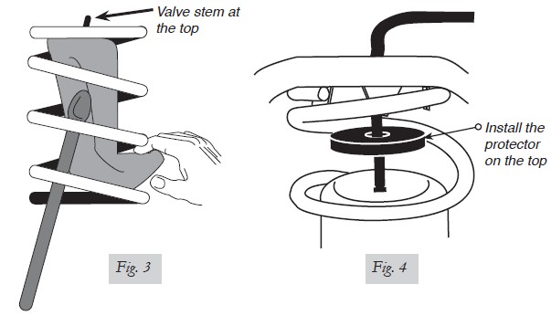
5. Push the air spring up within the coil by hand or with a blunt instrument such as a spoon-type tire iron.
6. When the air spring is completely within the coil, remove the cap and allow the air spring to assume its “as molded” shape. Push the cylinder down to the bottom of the spring so that the stem at the top can be accessed for attaching the hose.
7. Route the hose down from the outside of the frame, through the hole in the top spring seat (Fig. 4). Insert hose through the protector and attach to the cylinder per the next section.
INSTALLING THE AIR LINE
A tee air line installation is recommended unless the weight in the vehicle varies from one side to the other and unequal pressures are needed to level the load or compensate for axle torque transfer in racing applications. Dual air lines are used in this case.
TEE AIR LINE ROUTING
TO PREVENT THE AIR LINE FROM MELTING, MAINTAIN AT LEAST 8” (203.2MM) FROM THE EXHAUST SYSTEM TO THE AIR LINE.
1. Locate the desired tee location on the frame rail or cross member. Determine and cut adequate length of air line to reach from tee to the left and right side air springs.
LEAVE SUFFICIENT AIR LINE SLACK TO PREVENT ANY STRAIN ON THE FITTING DURING AXLE MOTIONS.
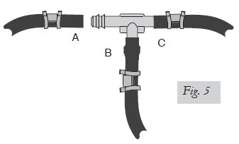
2. Slide an air line clamp onto the air line.
3. Push the air line over one side of the tee until all the barbs are covered. With a pair of pliers, slide the air line clamp forward until it fully covers the barbed section. Repeat entire procedure for other leg of the tee (Fig. 5).
4. Route the air line along the cross member and either the lower control arm or the upper spring seat to the air spring.
5. Insert the air line through the spring seat and spacers.
Use this procedure for all air line connections:
a. Slide the air line clamp onto the air line.
b. Push the air line over the barbed stem.
c. Compress the ears on the air line clamp with pliers and slide it forward to fully cover the barbed section.
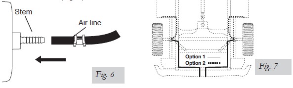
6. Push the air line onto the stem, covering all the barbs (Fig. 6). With the pliers, slide the air line clamp upward until it fully covers the barbed section.
7. Push the remaining air line over the last fitting on the tee and route it along the frame to the desired inflation valve location. Attach the air line with plastic straps or wire.
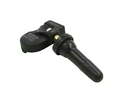
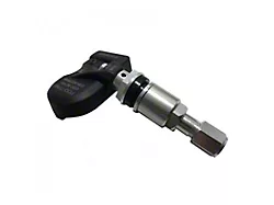
8. Select a location for the inflation valve in the gas cap well, the trunk, rear bumper, fender flange or behind license plate, insuring that the valve will be protected and accessible with an air hose (Fig. 7).
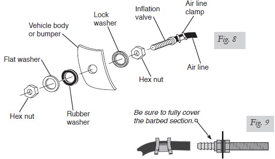
9. Drill a 5/16” (8mm) hole for the inflation valve and mount as shown (Fig. 8). The rubber washer serves as an outside weather seal.
10. Slide the air line clamp over the air line. Push the air line onto the fitting covering all barbs. Using pliers, slide the air line clamp forward until it fully covers the barbed section (Fig. 9).
DO NOT INFLATE AIR SPRINGS BEFORE READING THE MAINTENANCE AND OPERATION SECTION.
11. Continue to “Completing the Installation.”
DUAL AIR LINE ROUTING
TO PREVENT AIR LINE FROM MELTING, KEEP IT AT LEAST 8” (203MM) FROM EXHAUST SYSTEM.
1. Select a location for the inflation valves in the rocker panel flange, or rear bumper, assuring that each valve will be protected and accessible with an air hose.
2. Determine and cut adequate length of air line to reach from valve location to left side air spring.
LEAVE SUFFICIENT AIR LINE SLACK TO PREVENT ANY STRAIN ON FITTING DURING AXLE MOTIONS.
3. Insert the air line through the spring seat and spacer.
4. Slide air clamp onto the cut air line.
5. Push the air line onto the stem, covering all the barbed section (see Fig. 6). With pliers slide the air line clamp forward until it fully covers barbed section.
6. Repeat process for right side.
7. Drill 5/16” (8mm) hole for inflating valves and mount as illustrated. Rubber washer is for outside weather seal (see Fig. 8).
8. Route air line along control arm and frame to inflation valve location and cut off excess.
9. Slide a clamp onto the air line and push the air line over the fitting, covering all the barbs. With pliers slide the air line clamp forward until if fully covers the barbed section (see Fig. 9).
10. Raise axle or lower body until air springs lightly touch upper spring seat and lower spacers.
11. Check tail pipe clearance and ensure that it is at least 2-3 inches (50-75mm) from air springs. If necessary, loosen clamps and rotate or move to obtain additional clearance. If heat shields are supplied, install them. Attach shock absorbers if removed earlier in the installation.
DO NOT INFLATE AIR SPRINGS BEFORE READING THE MAINTENANCE AND
OPERATION SECTION.
COMPLETING THE INSTALLATION
1. Once the air line has been installed, raise the suspension or lower the body so that the air spring just touches the top and the bottom of the upper and lower spring mounts.
NOTE: The snap together protectors will nest inside of the coil spring upper mount. Inflate the air spring to 35psi (2.4 Bar).
2. Lower the vehicle to the ground. Read the “Maintenance and Servicing” section for proper care and for setting up the proper pressure in your suspension system.
CHECKING FOR LEAKS
1. Inflate the air spring to 30 PSI (2.1BAR).
2. Spray all connections and the inflation valves with a solution of liquid dish soap and water. Spot leaks easily by looking for bubbles in the soapy water.
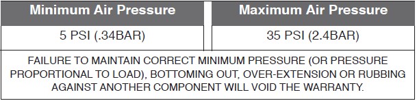
3. After the test, deflate the springs to the minimum pressure required to restore the system to normal ride height. Do not deflate to lower than 5 PSI (.34BAR).
4. Check the air pressure again after 24 hours. A 2-4 PSI (.14-.3BAR) loss after initial installation is normal. Retest for leaks if the loss is more than 5 PSI (.34BAR).
FIXING LEAKS
1. If there is a problem with the inflation valve:
a. Check the valve core by tightening it with a valve core tool.
b. Check the air line by removing the air line from the barbed type fitting. Cut the air
line off a few inches in front of the fitting and use a pair of pliers or vice grips to pull/
twist the air line off of the fitting.
DO NOT CUT OFF THE AIR LINE COMPLETELY AS THIS WILL USUALLY NICK THE BARB AND RENDER THE FITTING USELESS.
2. If the preceding steps have not resolved the problem, call Air Lift customer service at (800) 248-0892.
Before Operating
INSTALLATION CHECKLIST (To be completed by installer)
Clearance test — Inflate the air springs to 30 PSI (2.1BAR) and ensure there is at least 1/2” clearance around each bellow, away from anything that might rub against them. Be sure to check the tire, brake drum, frame, shock absorbers and brake cables.
Leak test before road test — Inflate the air springs to 30 PSI (2.1BAR), check all
connections for leaks with a soapy water solution. See “Checking for Leaks” on how to
spot leaks. All leaks must be eliminated before the vehicle is road tested.
Heat test — Be sure there is sufficient clearance from any heat sources — at least 6” (152mm) for air springs and air lines. If a heat shield was included in the kit, install it. If there is no heat shield, but one is required, call (800) 248-0892.
Fastener test — Recheck all bolts for proper torque. Re-torque after 100 miles (161 km).
Road test — The vehicle should be road tested after the preceding tests. Inflate the air springs to 25 PSI/2BAR (30 PSI [2.1BAR] if the vehicle is loaded). Drive the vehicle 10 miles and recheck for clearance, loose fasteners and air leaks.
Operating instructions — If professionally installed, the installer should review the
“Product Use, Maintenance and Servicing” section with the owner. Be sure to provide
the owner with all of the paperwork which came with the kit.
POST-INSTALLATION CHECKLIST
Overnight leak down test — Recheck air pressure after the vehicle has been used for 24 hours. If the pressure has dropped more than 5 PSI (.34BAR), then there is a leak that must be fixed. Either fix the leak yourself or return to the installer for service.
Air pressure requirements — Regardless of load, the air pressure should always be
adjusted to maintain ride height at all times.
Thirty day or 500 mile (800km) test —Recheck the air spring system after 30 days or 500 miles (800km), whichever comes first. If any part shows signs of rubbing or abrasion, the source should be identified and moved, if possible. If it is not possible to relocate the cause of the abrasion, the air spring may need to be remounted. If professionally installed, the installer should be consulted. Check all fasteners for tightness.
Product Use, Maintenance and Servicing
MAINTENANCE GUIDELINES
NOTE: By following these steps, vehicle owners will obtain the longest life and best results from their air springs.
1. Check the air pressure weekly.
2. Always maintain normal ride height. Never inflate beyond 35 PSI (2.4BAR).
3. If you develop an air leak in the system, use a soapy water solution to check all air line connections and the inflation valve core, before deflating and removing the spring.
4. When increasing load, always adjust the air pressure to maintain normal ride height. Increase or decrease pressure from the system as necessary to attain normal ride height for optimal ride and handling. Remember that loads carried behind the axle (including tongue loads) require more leveling force (pressure) than those carried directly over the axle.
CAUTION: FOR YOUR SAFETY AND TO PREVENT DAMAGE TO YOUR VEHICLE, DO NOT EXCEED MAXIMUM GROSS VEHICLE WEIGHT RATING (GVWR), AS INDICATED BY THE VEHICLE MANUFACTURER. ALTHOUGH YOUR AIR SPRINGS ARE RATED AT A MAXIMUM INFLATION PRESSURE OF 35 PSI (2.4 BAR), THE AIR PRESSURE ACTUALLY NEEDED IS DEPENDENT ON YOUR LOAD AND GVWR.
5. Always add air to the springs in small quantities, checking the pressure frequently. Cylinders require less air volume than a tire and inflate quickly.
6. Should it become necessary to raise the vehicle by the frame, make sure the system is at a minimum pressure (5 PSI [.34 Bar]) to reduce tension on the suspension/brake components. Use of on-board leveling systems do not require deflation or disconnection.
OPERATING TIPS
1. Inflate your air springs to 30 PSI (2.1BAR) before adding the payload. This will allow the air cylinder to properly mesh with the coil spring. After the vehicle is loaded, adjust your air pressure down to level the vehicle and for ride comfort.
2. When carrying a payload it will be helpful to increase the tire inflation pressure in proportion to any overload condition. We recommend a 2 PSI (.1BAR) increase above normal for each 100 lbs. additional load on the axle.
TROUBLESHOOTING GUIDE
1. Leak test the air line connections.
2. Inspect the air lines to be sure none are pinched. Zip ties may be too tight. Loosen or replace the tie and replace leaking components.
3. Inspect the air line for holes and cracks. Replace as needed.
4. Look for a kink or fold in the air line. Reroute as needed.
If the preceding steps do not solve the problem, it is possibly caused by a failed air spring - either a factory defect or an operating problem. Please call Air Lift at (800) 248-0892 for assistance.
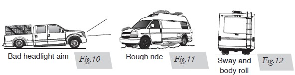
TUNING THE AIR PRESSURE
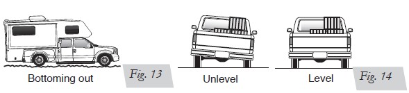
Pressure determination comes down to three things — level vehicle, ride comfort, and stability.
1. Level vehicle
If the vehicle’s headlights are shining into the trees or the vehicle is leaning to one side, then it is not level (fig. 17). Raise the air pressure to correct either of these problems and level the vehicle.
2. Ride comfort
If the vehicle has a rough and harsh ride it may be due to either too much pressure or not enough (fig. 18). Try different pressures to determine the best ride comfort.
3. Stability
Stability translates into safety and should be the priority, meaning the driver may need to sacrifice a perfectly level and comfortable ride. Stability issues include roll control, bounce, dive during braking and sponginess (fig. 19). Tuning out these problems usually requires an increase in pressure.
GUIDELINES FOR ADDING AIR
1. Start with the vehicle level or slightly above.
2. When in doubt, always add air.
3. If the front of the vehicle dives while braking, increase the pressure in the front air bags, if equipped.
4. If it is ever suspected that the air bags have bottomed out, increase the pressure (fig. 20).
5. Adjust the pressure up and down to find the best ride.
6. If the vehicle rocks and rolls, adjust the air pressure to reduce movement.
7. It may be necessary to maintain different pressures on each side of the vehicle. Loads such as water, fuel, and appliances will cause the vehicle to be heavier on one side (fig. 21). As much as a 50 PSI difference is not uncommon.