FREE 1 to 3-Day Delivery on Orders $149+ Details
How to Install SuperLift 2 in. Front Coil Spacer Leveling Kit (06-08 RAM 1500 Mega Cab) on your Dodge RAM

Shop Parts in this Guide
INTRODUCTION
Installation requires a professional mechanic. Prior to beginning, inspect the vehicles steering, driveline, and brake systems, paying close attention to the suspension link arms and bushings, anti-sway bars and bushings, steering linkage, ball joints and wheel bearings. Also check the steering sector-to-frame and all suspension-to-frame attaching points for stress cracks. The overall vehicle must be in excellent working condition; repair or replace all worn parts.
Read instructions several times before starting. Be sure you have all needed parts and know where they install. Read each step completely as you go.
NOTES:
• Prior to beginning the installation, check all parts and hardware in the box with the parts list below. If you find a packaging error, contact Superlift® directly. Do not contact the dealer where the system was originally purchased. You will need the control number from each box when calling; this number is located at the bottom of the part number label and to the right of the bar code.
• Front end realignment is necessary.
• A foot-pound torque reading is given in parenthesis ( ) after each appropriate fastener.
• Do not install any additional components or modify this system to gain additional suspension height.
• Prior to attaching components, be sure all mating surfaces are free of grit, grease, undercoating, etc.
• Speedometer recalibration will be recommended if a taller tire is used.
• A factory service manual should be on hand for reference.
• Use the check-off box “” found at each step to help you keep your place. Two “” denotes that one check-off box is for the driver side and one is for the passenger side.
PARTS LIST … The part number is stamped into each part or printed on an adhesive label. Identify each part and place the appropriate mounting hardware with it.
DISASSEMBLY
NOTE: Save all factory components and hardware for reuse, unless noted.
1) AIR INTAKE SYSTEM (gas models only)… Remove the air cleaner housing by loosening the clamp, then disconnect the air duct at the air cleaner cover. Lift the entire assembly from the four mounting pins and set the housing assembly aside.
2) PREPARE VEHICLE... Place vehicle in neutral. Raise front of vehicle with a jack and secure a jack stand beneath each frame rail, behind the lower trailing arms. Ease the frame down onto the stands, place transmission in low gear or “park”, and chock rear tires. Position a floor jack on each side of the front axle so that it supports, but does not raise, the axle. Remove front tires.
3) TRACK BAR… Disconnect the track bar from its axle mounting point.
4) VENT HOSE… Unclip the axle vent hose from the upper shock mount on the driver side.
5) ANTI-SWAY BAR LINKS… The anti-sway bar links connect the bar body-to-front-axle. Disconnect both links from the bar body. NOTE: Perform steps 6 through 10 one side at a time.
6) BRAKE HOSES… Remove the bracket securing the brake hose to the rear of axle-to- link arm brackets. Save the hardware and bracketry for re-use.
7) MARKING ECCENTRIC CAM BOLT ORIENTATION… The lower axle-to-frame link arms (one per side) are secured to the axle via eccentric cam bolts. Rotating these bolts changes front axle alignment. During reassembly, it is important that the eccentrics be returned to their original position to serve as a baseline for final alignment. Scribe a line on each eccentric, and the flanges they contact, for reference during reassembly.
8) UPPER and LOWER LINK ARMS … Loosen, but do not remove the four bolts (including eccentric cam bolts) that connect the upper and lower link arms to the front axle and frame.
9) SHOCK REMOVAL…
Remove the upper shock nut, followed by the three nuts that secure the shock tower -to- frame (nuts are accessed via the engine compartment). Remove the shock tower.
Remove the lower shock mounting bolt, then remove the shock through the top of the coil.
10) COIL SPRINGS… NOTE: Before removing the coil spring, make an indexing mark on the bottom coil spring wrap and the coil spring seat so the spring can be reinstalled in the same orientation as stock.
Remove the upper link arm-to-axle bolt then lower the axle enough to facilitate removing the coil spring.
Retain the factory rubber coil spring isolator, but discard the factory metal ring and attaching nuts.
Repeat steps 6 through 10 on opposite side.
ASSEMBLY
NOTE: Perform steps 11 and 12 one side at a time.
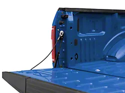
11) COIL SPACERS… [SEE PHOTO]
Position one coil spacer (#55-02-40004) in the coil tower, as shown. Using provided 7/16” flange nuts, start (do not tighten) the spacer nuts to temporarily hold it in place while the coil spring is installed.
Place the factory rubber isolator on top of the coil
spring, then position the coil beneath the coil spacer. Index the springs according to the marks made during disassembly.
NOTE: On some models the driveshaft must be disconnected at the axle to allow the axle to drop sufficiently for coil / spacer installation.
Raise the front axle enough to seat and hold the coil in place.
Reinstall the upper link arm-to-axle bolt. Do not tighten at this time.
Position the shock inside the coil spring then secure the bottom end using factory hardware
(89).
Remove the 7/16” flange nuts attaching the coil spacer-to-coil tower. Position the shock tower over the shock stem, and onto the coil spacer studs. Secure the coil spacer / shock tower assembly with the 10mm flange nuts (55).
12) BRAKE HOSES… Reattach the brake hose bracket that was detached in Step 5.
Perform steps 11 and 12 on opposite side.
13) VENT HOSE… Reattach the vent hose to the upper end of the driver side shock mount.
14) DRIVESHAFT… If disconnected, reconnect the front driveshaft (85).
15) TIRES / WHEELS... [SEE APPROPRIATE DIAGRAM] Tighten the lug nuts in the sequence shown.
WARNING: When the tires / wheels are installed, always check for and remove any corrosion, dirt, or foreign material on the wheel mounting surface, or anything that contacts the wheel mounting surface (hub, rotor, etc.). Installing wheels without the proper metal-to-metal contact at the wheel mounting surfaces can cause the lug nuts to loosen and the wheel to come off while the vehicle is in motion.
WARNING: Retighten lug nuts at 500 miles after any wheel change, or anytime the lug nuts are loosened. Failure to do so could cause wheels to come off while vehicle is in motion.
16) INITIAL CLEARANCE CHECK... With the vehicle’s frame rails still on jack stands, and the suspension “hanging” at full extension travel, cycle steering lock-to-lock and check all components for proper operation and clearances. Pay special attention to the clearance between the tires / wheels and brake hoses, wiring, etc.
17) ANTI-SWAY BAR LINKS… Lower vehicle to the floor. The suspension is now supporting vehicle weight. Connect both sway bar end links to the sway bar body using factory hardware (27).
18) TRACK BAR… Reattach the track bar to the axle mount using factory hardware (150).
19) UPPER and LOWER LINK ARMS… Prior to tightening the lower link arm-to-axle eccentric cam bolts (160), realign the eccentric cams using the scribe marks made during disassembly.
Tighten the lower link arms-to-frame (160). Tighten both axle and frame ends of the upper link arms (120).
20) AIR INTAKE SYSTEM (gas models only)… Position the air cleaner housing over the four pins; install the air duct to air cleaner cover and tighten the hose clamp (30 in. lbs.)
21) FINAL CLEARANCE and TORQUE CHECK... With vehicle on floor, cycle steering lock- to-lock and inspect the tires / wheels, and the steering, suspension, and brake systems for proper operation, tightness, and adequate clearance.
22) HEADLIGHTS... Readjust headlights to proper setting.
23) ALIGNMENT... Realign vehicle to factory specifications.
24) SUPERLIFT® WARNING DECAL… Install the WARNING TO DRIVER decal on the inside of the windshield, or on the dash, within driver’s view. Review the “IMPORTANT PRODUCT USE AND SAFETY INFORMATION / WARNINGS” text found at the end of this instruction sheet.