FREE 1 to 3-Day Delivery on Orders $149+ Details
How to Install Steel Craft STX600 Utility Running Boards - Black on your Dodge Ram

Shop Parts in this Guide
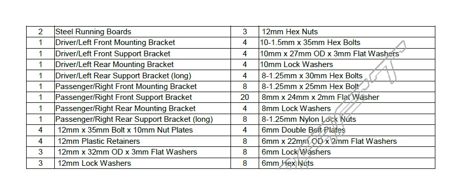
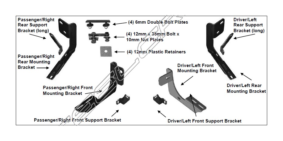
PARTS LIST:
PROCEDURE:
REMOVE CONTENTS FROM BOX. VERIFY ALL PARTS ARE PRESENT. READ INSTRUCTIONS CAREFULLY BEFORE STARTING INSTALLATION. DRILLING IS REQUIRED ON 2009-12 1500, 2010-12 25-3500 MODELS.
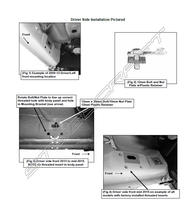
1. Starting at the driver side-front of the vehicle, remove the sealing tape covering the factory holes on the side of the inner panel, (Figure 1).
2. Determine the correct procedure to attach the driver side front Bracket for your model/year: Models without factory threaded inserts in body panel (Figures 1 & 3):
a. Partially thread a 12mm Plastic Retainer onto the threaded end of a 12mm Bolt and Nut Plate, (Figure 2). Insert the Bolt and Nut Plate into the oval hole and tighten the Plastic Retainer, (Figure 3). NOTE: The Plastic Retainer is designed to keep the Bolt/Nut Plate from falling into the body panel and to aid in Bracket installation.
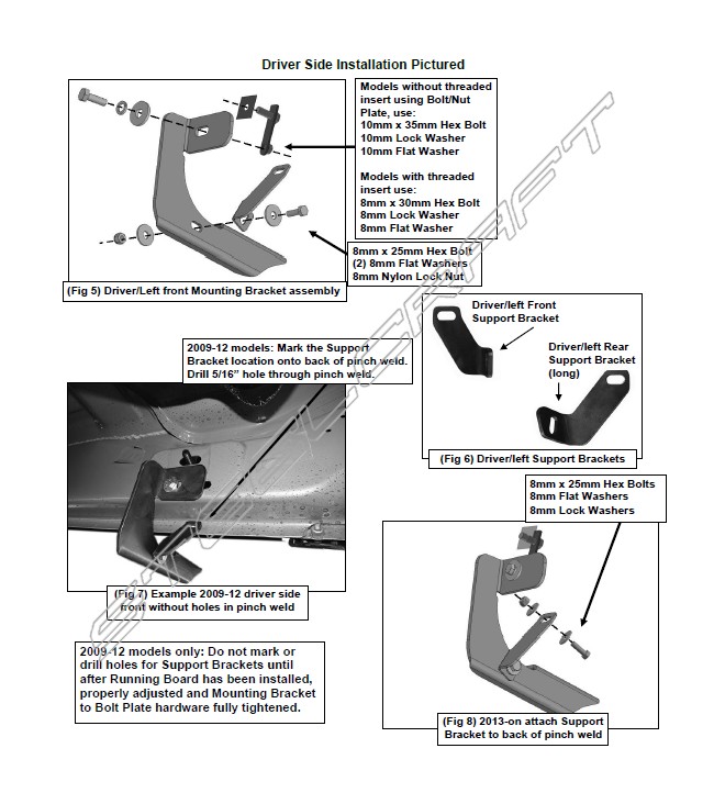
b. Select the driver side front Mounting Bracket, (Figures 5 & 9). Rotate the 12mm Bolt and Nut plate until the threaded nut lines up with the hole in the Mounting Bracket and body, (Figure 3). Attach the Bracket to the threaded Nut Plate with (1) 10mm x 35mm Hex Bolt, (1) 10mm Lock Washer and (1) 10mm Flat Washer, (Figures 5 & 7). Do not fully tighten hardware at this time.
Models with factory threaded inserts:
a. Attach the driver side Front Bracket to the threaded insert with (1) 8mm x 30mm Hex Bolt, (1) 8mm Lock Washer and (1) 8mm Flat Washer, (Figures 4, 5 & 7). Leave hardware loose.
3. Next, select the driver side front Support Bracket, (Figure 6). Attach the Bracket to the front of the front Bracket with (1) 8mm x 25mm Hex Bolt, (2) 8mm Flat Washers and (1) 8mm Nylon Lock Nut, (Figures 5 & 7). Rotate the Support Bracket to the back of the pinch weld. Line up the slot in the top of the Support Bracket with the factory holes in the pinch weld. Attach the Bracket to the pinch weld with (1) 8mm x 25mm Hex Bolt, (2) 8mm Flat Washers and (1) 8mm Nylon Lock Nut, (Figures 7, 8 & 15). Do not fully tighten hardware at this time. IMPORTANT: 2009-12 models are not equipped with factory holes and will require drilling through the pinch weld to attach the Support Bracket, (Figure 7). Do not drill through pinch weld at this time, (see Step 8).
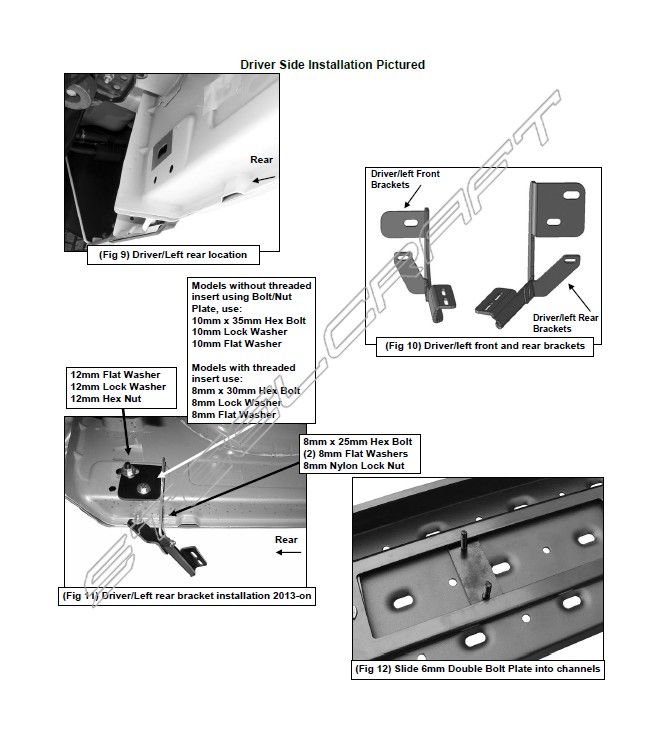
4. Move along the side of the body panel to the rear mounting location, (Figure 9). Select (1) 12mm Bolt/Nut Plate. Repeat Step 2 to install the Bolt/Nut Plate. Select the driver side rear Bracket (Figure 10). Attach the Bracket to the Bolt/Nut Plate with (1) 12mm Flat Washer, (1) 12mm Lock Washer and (1) 12mm Hex Nut, (Figure 11). Line up the remaining hole in the Bracket with the hole in the inner body panel. Rotate the Bolt and Nut Plate until the threaded end (Nut) lines up with the hole in the Bracket. Secure with (1) 10mm x 35mm Hex Bolt, (1) 10mm Lock Washer and (1) 10mm Flat Washer, (Figure 11). Do not fully tighten hardware at this time.
a. IMPORTANT NOTE: Models with threaded insert, attach the Bracket to the threaded insert with (1) 8mm x 30mm Hex Bolt, (1) 8mm Lock Washer and (1) 8mm Flat Washer. The 10mm hardware will not be required (Step 2). Snug but do not tighten hardware.
5. Repeat Step 3 to install the longer driver side rear Support Bracket, (Figures 6, 10 & 11).
6. Once both Brackets have been completely installed, select (1) Running Board. Place the Running Board on top of the Brackets. Locate the channels in the bottom of the Running Board. Select (2) 6mm Double Bolt Plates. Insert the Bolt Plates into the channels in the bottom of the Running Board closest to the Brackets, (Figure 12). Lift the Running Board up and guide the studs through the Brackets.
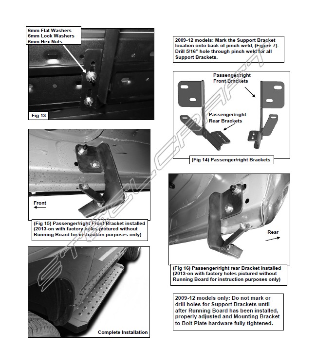
7. Attach the Running Board to the front and rear Brackets with (4) 6mm Flat Washers, (4) 6mm Lock Washers and (4) 6mm Hex Nuts, (Figure 13). NOTE: The Running Board is designed to fit close to the vehicle. It may be necessary to loosen the Bracket hardware and tilt the Brackets downward to insert the Running Board between the Brackets and the body. Do not tighten hardware at this time.
8. Properly level and adjust the Running Board and fully tighten all hardware.
2009-12 models requiring drilling for Support Brackets:
a. Make sure the Running Board is level to the vehicle. Line up the slot on the Support Bracket with the back of the pinch weld. Mark the location of the slot onto the pinch weld, (Figure 7).
b. Drill a 5/16” hole through the pinch weld. IMPORTANT: Do not drill too close to the bottom edge of the pinch weld. Drill the hole toward the center of the marked slot.
c. Attach each Support Bracket to the back of the pinch weld with (1) 8mm Hex Bolt, (2) 8mm Flat Washers and (1) 8mm Nylon Lock Nut, (Figures 11, 15 & 16). Repeat for all Support Brackets.
d. Check Running Board for level then fully tighten all hardware.
9. Move to the passenger side of the vehicle. Remove tape covering front and rear locations. Repeat Steps 4-8 for passenger side installation, (Figures 14-16). NOTE: Refer to Figure 14 to identify the correct Mounting Bracket for each of the remaining locations.
10. Fully tighten all hardware once installation is complete.
11. Do periodic inspections to the installation to make sure that all hardware is secure and tight.
To protect your investment, wax this product after installing. Regular waxing is recommended to add a protective layer over the finish. Do not use any type of polish or wax that may contain abrasives that could damage the finish.
For black powder coated finishes: Mild soap may be used to clean the Running Board.