 FREE 1 to 3-Day Delivery on Orders $149+ Details
How to Install SkyJacker 6-7 in. Standard Suspension Lift Kit w/ Shocks (14-17 4WD Sierra 1500, Excluding Denali) on your GMC Sierra
Tools Required
- Safety Glasses
- Metric / Standard Wrenches & Sockets
- Allen Wrenches
- Floor Jack
- Jack Stands
- Measuring Tape
- Torque Wrench
- Reciprocating Saw
- Grinder
- Cut Off Wheel

Shop Parts in this Guide
IMPORTANT NOTES:
• If larger tires (10% more than the OEM diameter) are installed, speedometer recalibration will be necessary. Contact your local GM dealer or an authorized dealer for details.
• After installation, a qualified alignment facility is required to align the vehicle to the OEM specifications.
Front Installation:
1. With the vehicle on a level concrete or asphalt surface, set the emergency brake & block the rear tires / wheels. Place a floor jack under the lower control arm front cross member & raise the front of the vehicle. Place jack stands under the frame rails behind the front wheel wells & lower the frame onto the jack stands.
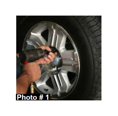
2. Remove the front tires / wheels using a 22mm socket. (See Photo # 1)
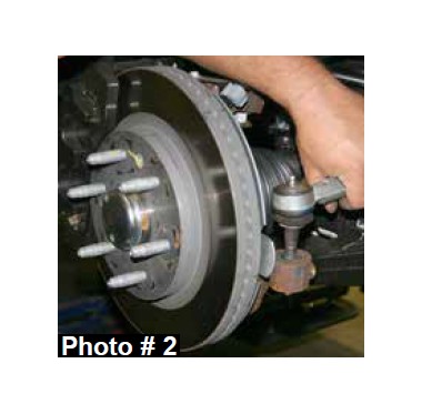
3. Remove the OEM outer tie rod end nuts from the OEM steering knuckles using a 18mm socket & disconnect the OEM outer tie rod ends from the OEM steering knuckles using a tie rod puller or similar tool. (See Photo # 2)
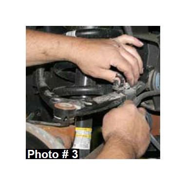
4. Disconnect the OEM brake calipers from the OEM brake rotors & disconnect the OEM brake lines from the OEM upper A-arms. (See Photo # 3) Simply wire the OEM brake calipers out of the way. It will not be necessary to disconnect the OEM brake lines from the OEM brake calipers at this time.
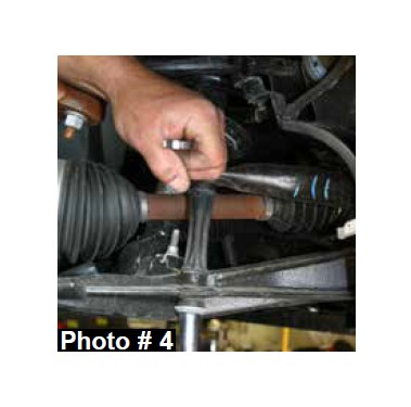
5. Remove the OEM sway bar end links using a 15mm socket & remove the OEM sway bar. (See Photo # 4)
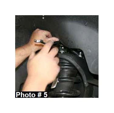
6. Remove the OEM strut assemblies by removing the lower mounting bolts & upper strut retaining nuts. (See Photo # 5)
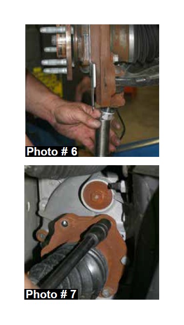
7. Disconnect the OEM upper & lower A-arms from the OEM steering knuckles using a 18mm socket. It may be necessary to strike the side of the OEM steering knuckles to dislodge the OEM ball joints. Be careful not to damage the OEM ball joints. (See Photo # 6)
8. Remove the OEM CV axles using a 15mm socket. (See Photo # 7)
9. Remove the OEM front skid plates using a 15mm socket. Disconnect the OEM lower A-arms using a 18mm & 24mm socket.
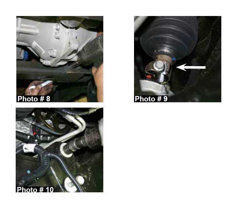
10. Remove the OEM rear cross member using a 18mm socket. (See Photo # 8)
11. Disconnect the OEM steering shaft & all electrical connections from the OEM rack & pinion. (See Arrow Photo # 9) Remove the OEM rack & pinion using a 18mm & 24mm socket. (See Photo # 10)
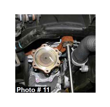
12. Disconnect the OEM front drive shaft from the front differential & support the front differential using a transmission jack. Remove the OEM front differential mounting bolts using a 15mm & 18mm socket & remove the front differential. (See Photo # 11)
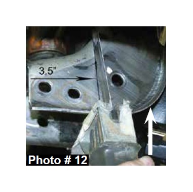
13. It will be necessary to cut the driver side frame rail where the OEM rear cross member was located. Measure toward the frame 3.5" & cut using a reciprocating saw or similar tool. (See Photo # 12) Note: It will be necessary to grind down the forward lip on the frame for clearance of the new Skyjacker CV axle spacers. (See Arrow in Photo # 12)
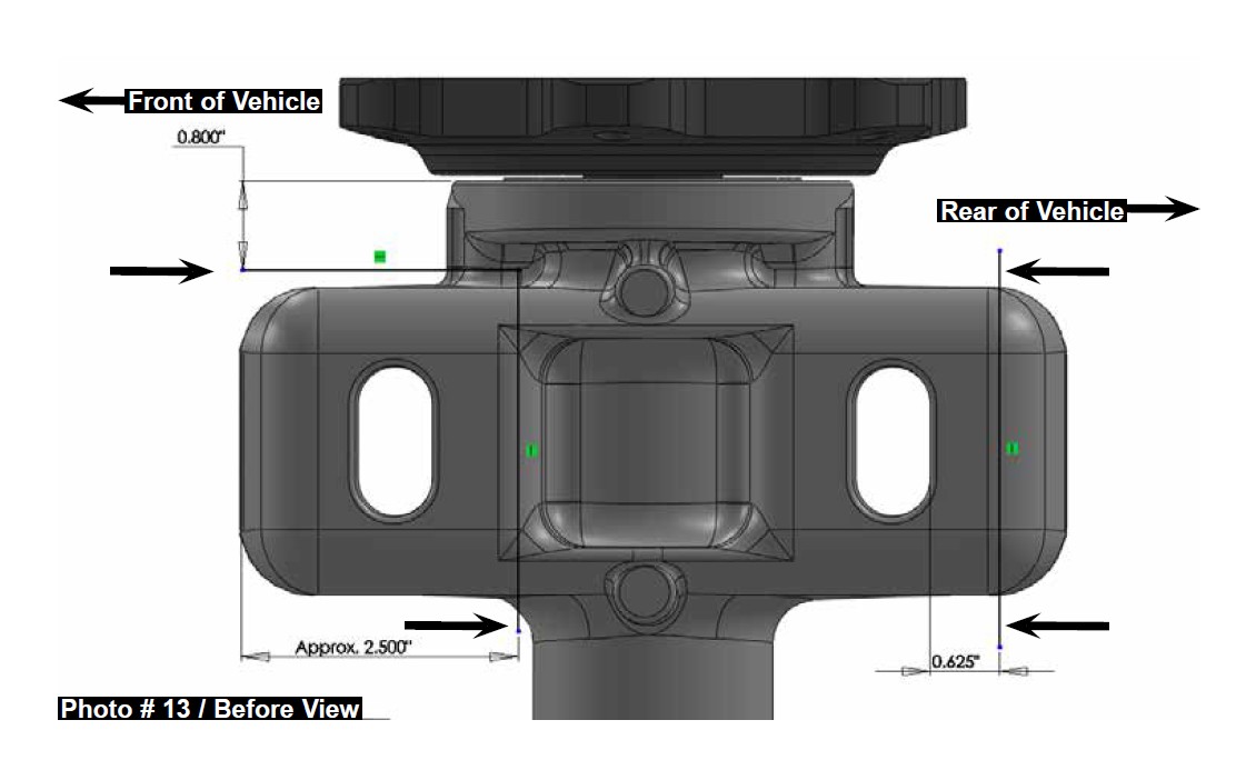
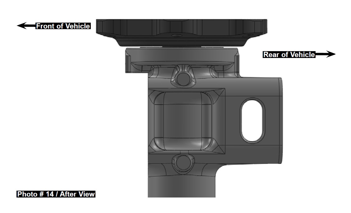
14. It will be necessary to modify the front & rear of the passenger side differential mounting pad for clearance. Measure from the edge of the rear slotted mounting hole of the passenger side differential mounting pad toward the rear of the vehicle. Mark a line at .625" & cut along the the marked line using a reciprocating saw or similar tool. Measure from the front edge of the front passenger side differential mounting pad & mark a line at 2.50". Measure from the outer edge of the front passenger side differential housing inward & mark a line at .800". Cut along both marked lines using a reciprocating saw or similar tool. (See Photo # 13 / Before View & # 14 / After View)
15. Install the OEM rack & pinion using a 18mm & 24mm socket. (See Photo # 10) Reconnect the OEM steering shaft & all electrical connections to the OEM rack & pinion. (See Arrow Photo # 9)
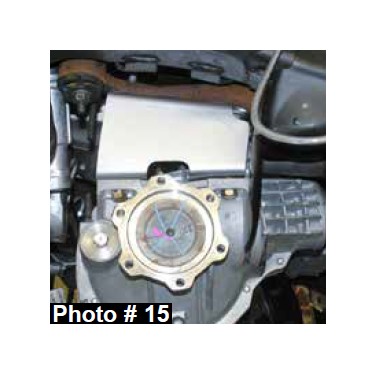
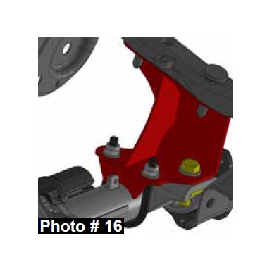
16. Install the new Skyjacker driver & passenger differential brackets using the OEM hardware with the tallest portion of the new brackets toward the front of the vehicle. Install the front differential using the supplied 7/16" u-bolt, square shim, 9/16" x 2" coarse thread bolt, washers, & nuts on the passenger side & the supplied 1/2" x 2" fine thread bolts, washers, & nuts on the driver side. Note: Be sure to use the supplied square shim on the passenger side rear differential pad where it was previously cut. (See Photo # 15 & # 16)
17. Reconnect the OEM front drive shaft.
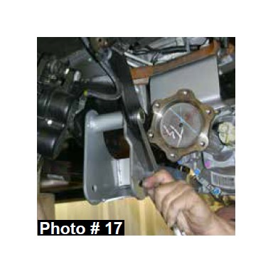
18. Install the new Skyjacker rear cross member using the supplied 5/8" x 5 1/2" fine thread bolts, washers, & nuts. (See Photo # 17)
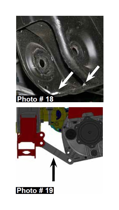
19. Install the new Skyjacker front cross member using the supplied 5/8" x 4 1/2" fine thread bolts, washers, & nuts. (See Photo # 18) Note: It will be necessary to to grind the inside lower corners of the OEM front cross member for proper fitment of the new Skyjacker front cross member. (See Arrows Photo # 18)
20. If installing the optional new Skyjacker differential anti torque arm (Part # C766TA / Sold Seperately), install it at this time. If not installing the optional new Skyjacker differential anti torque arm, proceed to Step # 21. Install the new Skyjacker differential anti torque arm by installing the supplied bushing & sleeve in the eyelet of the new differential anti torque arm. Attach the eyelet to the lower mounting location of the new Skyjacker front cross member using the supplied 1/2" x 2 1/2” fine thread bolt, washers, & nut. Attach the lower ear to the front differential using the supplied 9/16" x 2 1/2” fine thread bolt, washers, & nut. (See Arrow Photo # 19)
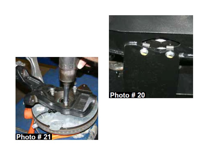
21. Attach the supplied 3/8" coarse thread extruded u-nuts to the new front & rear cross member mounting locations & install the new Skyjacker front differential skid plate to the new front & rear cross members using the supplied 3/8" x 1" coarse thread bolts & washers. (See Photo # 20)
22. Attach the OEM A-arms to the new Skyjacker front & rear cross members using the OEM hardware.
23. Remove the OEM hub bearing assemblies from the OEM steering knuckles using a 15mm socket. Install the OEM hub bearing assemblies to the new Skyjacker steering knuckles using the OEM hardware. (See Photo # 21)
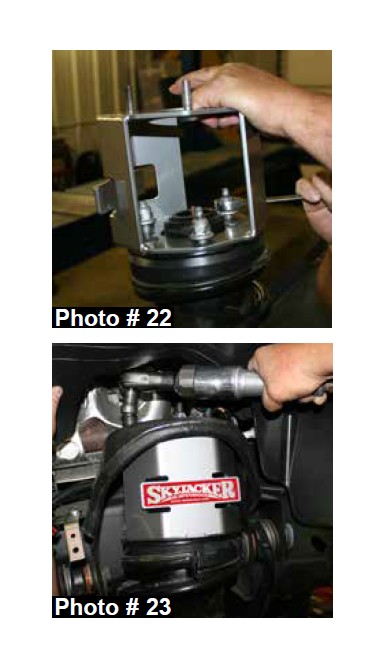
24. Install the new Skyjacker strut spacers on the top of each OEM strut assembly using the OEM hardware & 18mm wrench. (See Photo # 22)
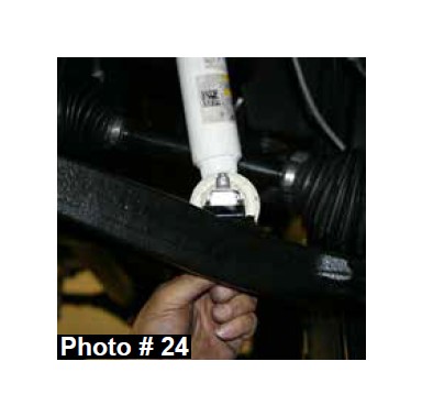
25. Install the upper mount of the strut assemblies using the supplied 10mm nuts. (See Photo # 23) 6" Lift: Install the lower mount of the strut assemblies using the OEM hardware. 7" Lift: Place the new Skyjacker lower strut spacer under each strut lower mount & install the lower strut assemblies using the supplied 10mm x 80mm bolts & washers. (See Photo # 24)
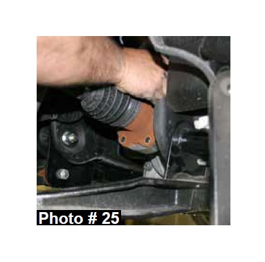
26. Attach the new Skyjacker steering knuckles to the upper & lower A-arms using the OEM hardware. Install the new Skyjacker CV axle spacers & OEM CV axles using the supplied 10mm x 70 mm bolts & thread locking compound. (See Photo # 25)
27. Attach the OEM ABS lines to the side of the new Skyjacker steering knuckles using the supplied cable clamps & 6mm x 12mm bolts.
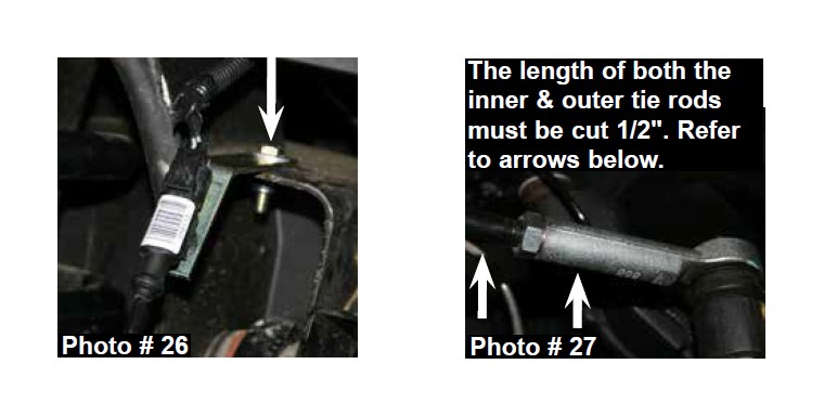
28. Install the new Skyjacker ABS line brackets to the frame using the supplied 5/16" x 1" fine thread bolts, washers, & nuts. (See Photo # 26) Install the new Skyjacker brake lines using the supplied instruction sheet.
29. In order to maintain the OEM alignment specifications, the OEM inner &outer tie rods must be cut to obtain proper toe in. Remove the OEM outer tie rods from the OEM inner tie rods. Leaving the OEM jam nuts screwed onto the OEM inner tie rods, measure 1/2" from the end of the OEM inner tie rods & mark a line. Measure 1/2" from the end of the OEM outer tie rods & mark a line. Using a cut off wheel or similar tool, cut along the marked lines. Unscrew the OEM jam nuts to chase the threads of the OEM inner tie rods. Reinstall the OEM outer tie rods to the OEM inner tie rods. The OEM driver & passenger side tie rod ends must be cut & adjusted equally to allow for proper toe in adjustment. (See Photo # 27)
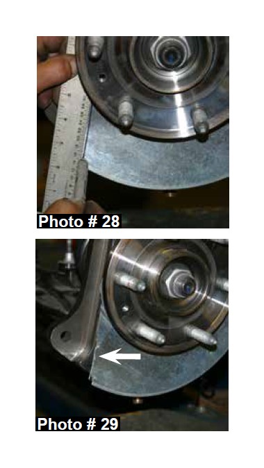
30. Attach the OEM outer tie rod ends to the new Skyjacker steering knuckles using the OEM hardware. Mark a line along the brake caliper mounting surface of the new steering knuckles & trim the OEM brake dust sheilds for proper brake caliper fitment using a cut off wheeel or similar tool. (See Photo # 28 & # 29) Reinstall the OEM brake rotors & OEM brake calipers using the OEM hardware.
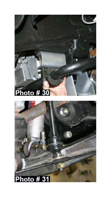
31. Reinstall the OEM sway bar using the new Skyjacker sway bar lowering brackets. The new sway bar lowering brackets will install between the OEM sway bar & the OEM mount on the frame using the supplied 10mm x 30mm bolts, washers, & nuts. (See Photo # 30) Install the new Skyjacker sway bar end links with the supplied smaller 5/8" washer on top of the OEM A-arm & the supplied larger 5/8" washer & nut on the bottom of the OEM A-arm. Note: Install the new sway bar end links with the pivoting end at the A-arm. (See Photo # 31)
32. Install the front tires / wheels using a 22mm socket & lower the front of the vehicle to the ground.
Rear Installation:
33. Block the front tires / wheels, raise the rear of the vehicle, & properly support the frame rails using jack stands.
34. Remove the rear tires / wheels using a 22mm socket.
35. Support the rear differential & remove the OEM rear shocks & OEM U-bolts.
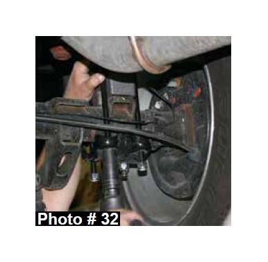
36. Rear Lift Block Installation: 6" Lift: Remove the OEM rear blocks & install the new Skyjacker 5.5" rear lift blocks with the thick end towards the rear of the vehicle. Install the new Skyjacker U-bolts. (See Photo # 32) 7" Lift: Install the new Skyjacker 5.5" rear lift blocks on top of the OEM rear blocks with the thick end towards the rear of the vehicle & install the new Skyjacker U-bolts.
37. Rear Leaf Spring Installation: Remove the OEM leaf springs & install the new Skyjacker leaf springs on top of the OEM rear blocks with the thicker portion of the degree shim facing towards the rear of the vehicle. Note: It will be necessary to lower the gas tank to gain access to the OEM forward leaf spring mounting bolt.
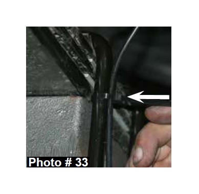
38. Remove the OEM ABS lines from the plastic connectors on the frame & attach the OEM ABS lines to the outside of the new Skyjacker U-bolts using the supplied plastic ties. (See Photo # 33)
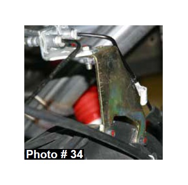
39. Install the new Skyjacker rear brake line bracket to the rear differential using the OEM hardware. Place the OEM rear brake line bracket on top of the new rear brake line bracket. Attach the OEM rear brake line bracket to the driver side mounting location of the new rear brake line bracket using the supplied 5/16" x 1" fine thread bolt, washers, & nut. (See Photo # 34) Note: In order to prevent contact between the OEM rear hard brake lines & the new rear brake line bracket, it will be necessary to slightly bend the OEM rear hard brake lines for clearance.
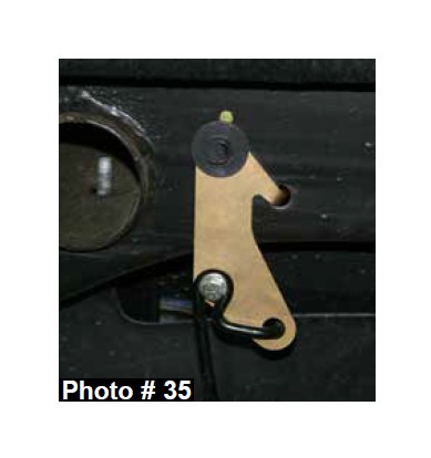
40. Remove the OEM emergency cable bracket from the driver side frame & install the new Skyjacker emergency cable bracket to the frame using the OEM hardware. Attach the OEM emergency cable to the new emergency cable bracket using the supplied 5/16" x 1" fine thread bolt, SAE washer, USS washer, & nut. (See Photo # 35)
41. Install the new Skyjacker rear shocks using the OEM hardware.
42. Install the rear tires / wheels using a 22mm socket, & lower the rear of the vehicle to the ground.
FINAL NOTES:
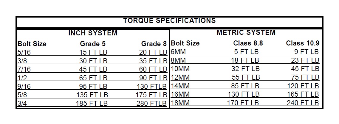
• After the installation is complete, double check that all nuts & bolts are tight. Refer to the following chart for the proper torque specifications. (Do not retighten nuts & bolts where thread lock compound was used.)
• With the vehicle placed on the ground, cycle the steering lock to lock & inspect the steering, suspension, brake lines, front & rear drivelines, fuel lines, & wiring harnesses for proper operation, tightness, & adequate clearance.
• Have the headlights readjusted to the proper settings.
• Have a qualified alignment center realign the vehicle to the OEM specifications.
• After the first 100 miles, check all of the hardware for the proper torque & periodically thereafter.
*The above specifications are not to be used when bolt is being installed with a bushing.


