FREE 1 to 3-Day Delivery on Orders $149+ Details
How to Install S & B Cold Air Intake w/ Oiled Cleanable Cotton Filter (09-17 5.7L RAM 1500) on your Dodge RAM
Tools Required
- 8mm, 10mm, 13mm Wrench & Socket
- Pin Removal Tool or Flat Blade Screwdriver
- 7/16” Wrench and Socket
- 5/16” Nut Driver or Flat Blade Screwdriver
- Phillips Screwdriver

Shop Parts in this Guide
Before You Start
• Please read the entire product guide before proceeding.
• Ensure all components listed on page 4 are present.
• If you are missing any of the components, call our customer support at (909) 947-0015.
• Do not work on your vehicle while engine is hot.
• Make sure the engine is turned off and the vehicle is in Park or the Parking Brake is set.
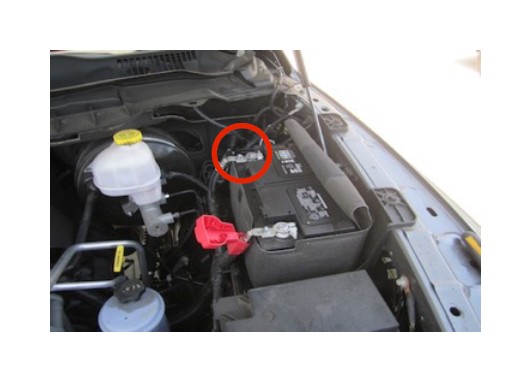
1. With the ignition switched off and the parking brake set, disconnect the negative battery cable on the driver’s side.
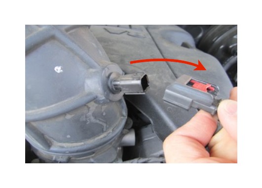
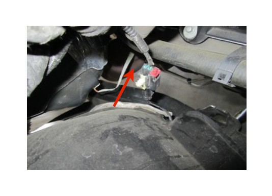
2. Disconnect the electrical connection for the Temp (IAT) Sensor. Note the sensor’s orientation for the re-install.
3. Loosen the hose clamp connecting the tube to the air box and the clamp attaching the tube to the throttle body. Then remove intake tube from the truck.
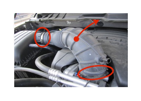
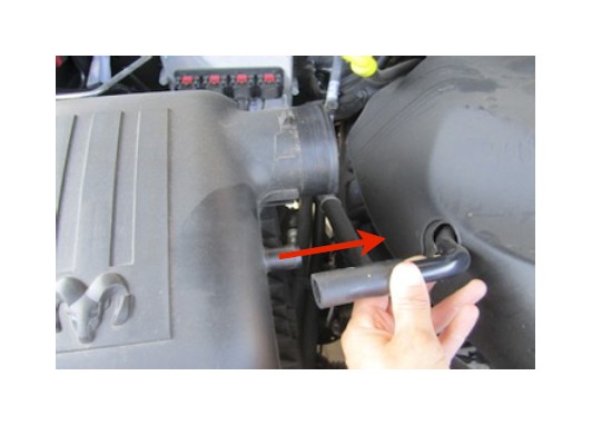
4. Remove the crank case vent tube from the air box.
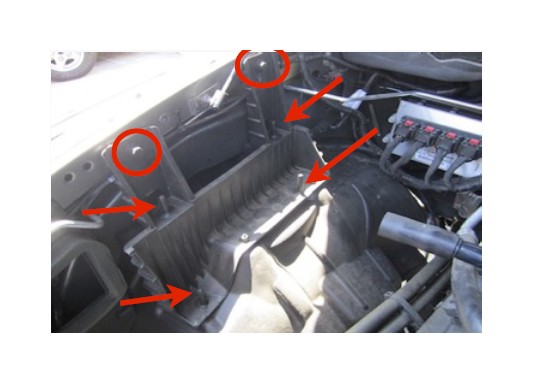
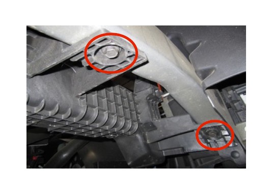
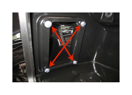
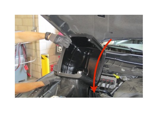
5. Remove air box by carefully pulling the air box up out of the four pins in the air box tray. Then remove the two bolts mounting the tray to the frame using 13mm socket.
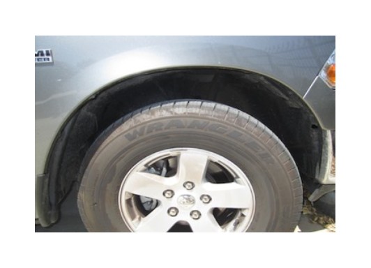
6. Remove the seven screws securing the wheel liner using 8mm socket. Then remove the 3 push pins. S&B has supplied new panel pins in the event that the OE pins are damaged during removal.
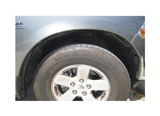
7. From inside the engine compartment, carefully pull the wiring harness connector out from the wheel liner. Then remove the wheel liner from the truck.
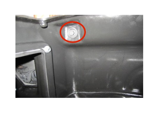
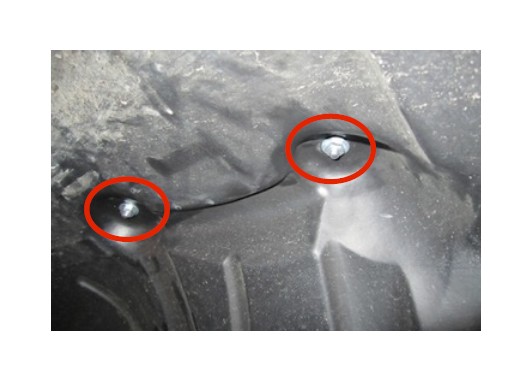
8. Using 13mm socket, remove the other 2 bolts securing the air box tray. Then remove the tray from the truck
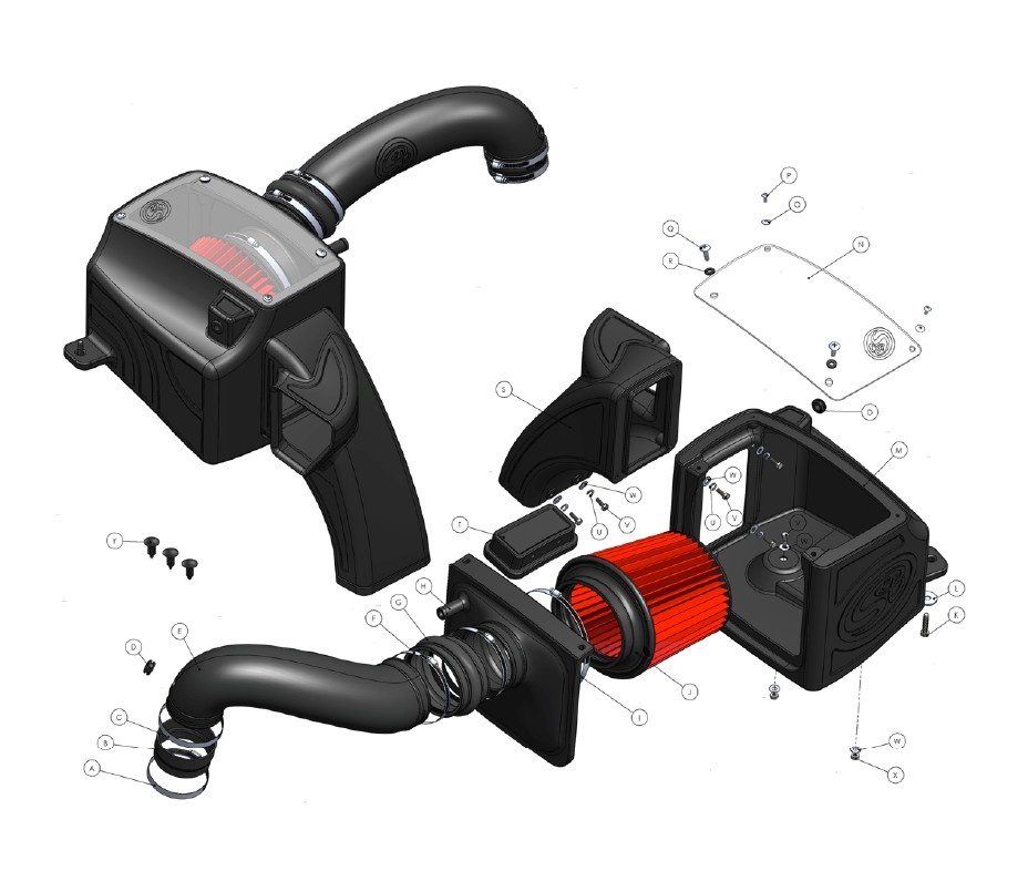
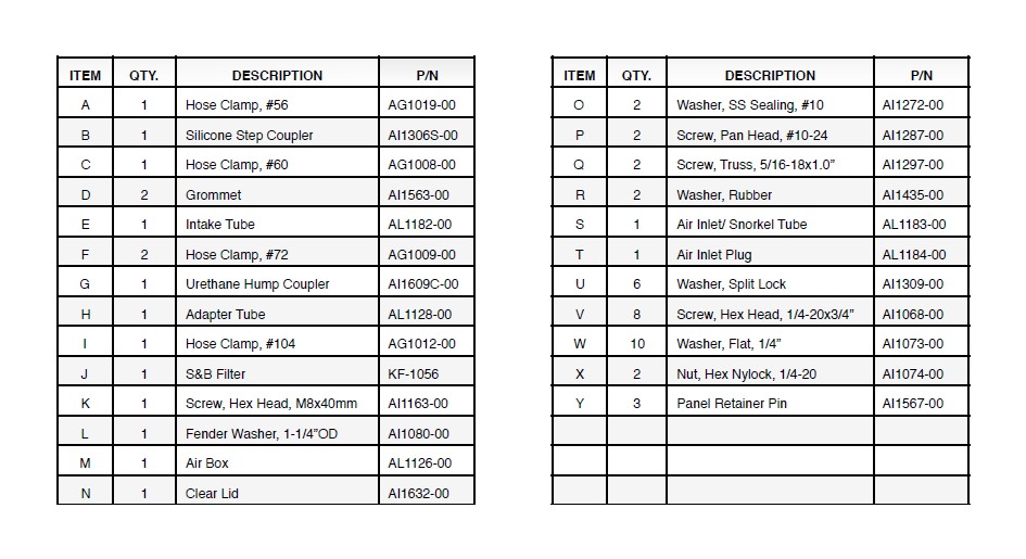
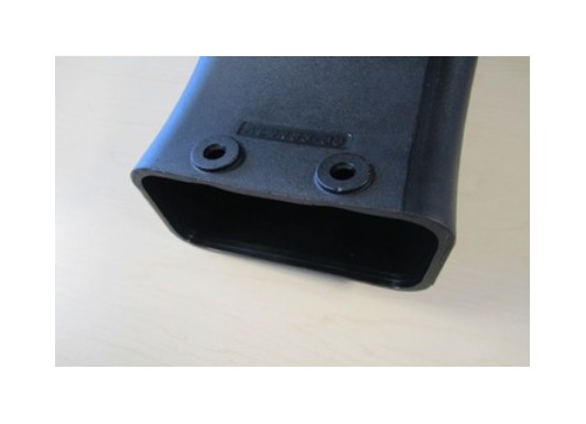
9. Insert the supplied Grommet (D) into the Air Box (M).
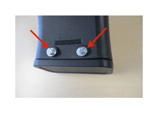
10. Insert the Air Inlet tube (S) onto the Air Box (M) and secure using the supplied 1/4”-20x3/4” screws (V), 1/4” Lock washers (U) and 1/4” Flat washers (W).
11. For those concerned about minimal engine heat; insert the Air Inlet Plug (T) into the end of the Air Inlet tube (S). Attach using the supplied 1/4”-20x3/4” screws (V), 1/4” Lock washers (U) and 1/4” Flat washers (W). For those seeking additional air flow, set the Air Inlet Plug aside and save all the supplied hardware. (See page 3 for more info and test results)
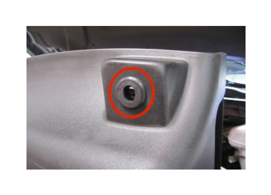
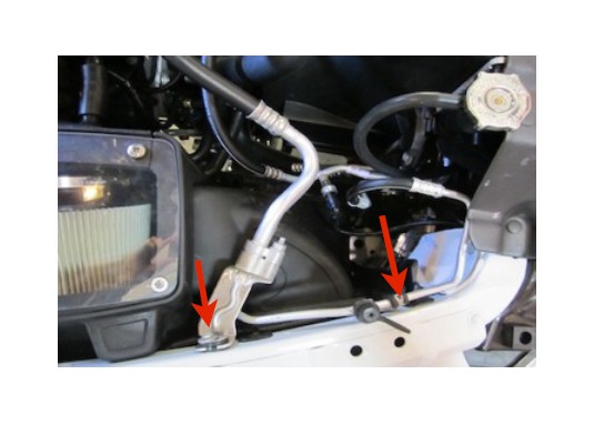
12. On 2013 models; it may be necessary to shift the A/C line assembly forward to gain clearance around the Inlet tube. This can be done loosening the two screws attaching the assembly to the fender.
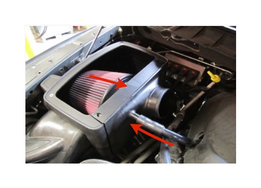
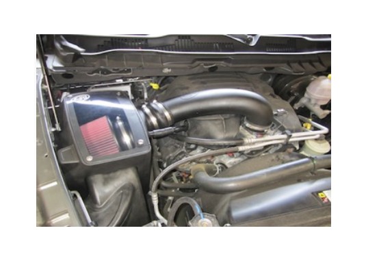
13. Carefully install the air box assembly into the truck at an angle as shown below.
14. Using the OE bolt, secure the air box assembly to the frame. Leave loose for now. Secure the A/C line assembly if it was loosened in Step #12.
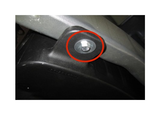
15. From inside the wheel well, attach the air box to frame using the supplied M8 x 40mm Hex bolt (K) and Fender Washer (L). Then secure both bolts mounting the air box to the frame.
16. Reinstall the wheel liner using 5 of the OE screws and 3 supplied Panel Pins (Y). Reinstall wiring harness connector into wheel liner that was removed in Step #7.
17. Secure the wheel liner to the air box using two supplied 1/4”-20x3/4” screws (V) and Flat washers (W) inside the air box. Use the 1/4” Nylock nuts (X) and 1/4” Flat washers (W) under the wheel liner.
18. Insert the S&B Filter (J) onto the Adapter Tube (H) and secure the #104 Hose Clamp (I). Install the assembly into the Air box. Then push the valve cover breather hose onto the stem of the Adapter tube.
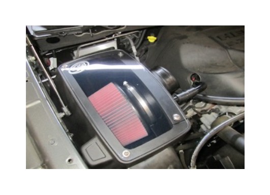
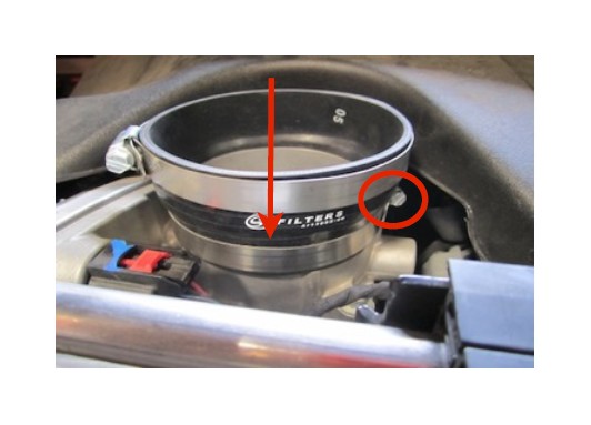
19. Install the Clear Lid (N) using the supplied 5/16” S.S. Screws (Q) and Rubber Washers (R) along with the 10-24 Screws (P) and SS Sealing Washers (O). This will secure the Filter Adapter to the Air Box as well. (Do not over tighten!)
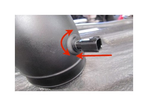
20. Note the OE Temp. Sensor orientation. Then carefully pull it out of the OE tube. Insert the supplied Grommet (D) into the Intake Tube (E). Carefully push the Temp. sensor into the grommet using a twisting motion. Be sure to match the OE orientation.
21. Place a #72 Hose clamp (F) over each end of the Hump Coupler (G). Then slide the hump coupler over the end of the Intake Tube(E).
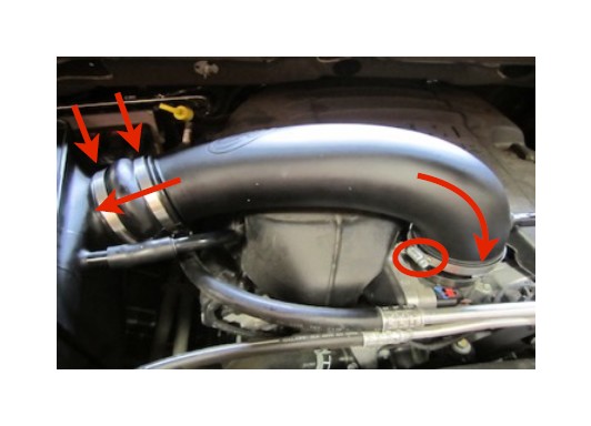
22. Secure the Silicone Step Coupler (B) to the throttle body using a #56 Hose Clamp (A). Place the #60 Hose Clamp (C) around the top of the Silicone coupler.
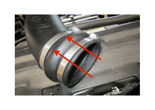
23. Insert the Intake tube assembly into the Silicone Coupler, then slide the Hump Adapter over the Adapter Tube. Tighten all hose clamps when you are satisfied with the positioning.
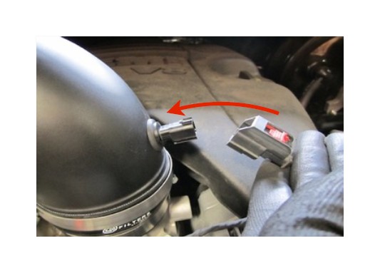
24. Reconnect the Temp. Sensor wiring harness.
25. Reconnect the battery. Inspect your installation, make sure the kit is properly positioned and all fasteners are secure. Affix the CARB sticker (if applicable) near the intake kit. The installation is now complete.
Testing and Maintenance
• Engage parking brake and start your engine. Listen for abnormal noises. If an air leak is detected, reinspect hoses and connections as they may need to be repositioned and tightened.
• S&B FILTERS recommends that you keep your OE intake system in the event it is required in the future.
• In order to maintain your warranty, all connections and components must be checked periodically for alignment and for proper tension on all connections. Failure to do so may void your warranty.
• Use only S&B FILTERS cleaning and oil products to service your filter. Using any other brand oil and or cleaners on your S&B air filter may void your warranty. See www.sbfilters.com for complete warranty information.