FREE 1 to 3-Day Delivery on Orders $149+ Details
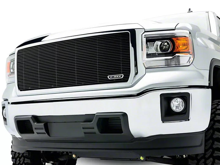
How to Install T-REX Billet Series Upper Grille Insert - Black (14-15 Sierra 1500, Excluding Denali) on your GMC Sierra
Installation Time
45 minutes
Tools Required
- Socket and Ratchet Set
- Flat/Phillips Screwdrivers
- Torx Bits
- Grinder And Grinding Wheel
Shop Parts in this Guide
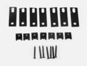
PARTS LIST
(7) #8 Six Head Screws
(7) #8 U-Nuts
(7) Extension Brackets
(1) Grille
PLEASE READ AND UNDERSTAND ALL INSTRUCTIONS BEFORE INSTALLATION. Auto makers offer varied models to each vehicle and occasionally manufacture more than one body style of the same model. To assure your part is correct; our tech department can be contacted at [email protected] to verify ftment or assist with tech questions. All other inquires can be directed to [email protected]. In the event you do not have internet access please call 1-800-287-5900.
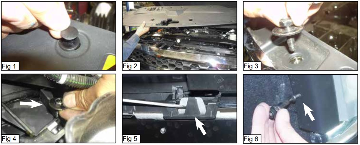
Step 1 Factory Grille Removal
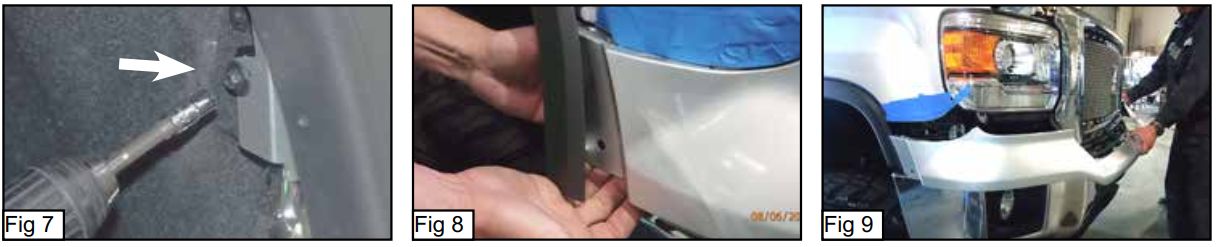
Start of by removing the twelve plastic pop clips along the top of the radiator cover using flat screw driver (Fig 1). Remove the plastic radiator cover (Fig 2). Remove the four 10mm bolts located along the top of the factory grill (Fig 3). From underneath the vehicle remove four 10mm bolts from the bottom backside of the factory grille, two are located in the middle area and two are located underneath each headlamp (Fig 4). From underneath the front of the vehicle use a flat screwdriver to unclip 6 plastic latches, these latches hold the top plastic bumper pad to the metal lower section of the bumper (Fig 5). Now using a T15 torx bit remove two torx bolts from the top and
front edges of each front fenderwell (Fig 6) these bolts hold the fender trim to the fender. Pull back the fender trim and remove one 7mm bolt from the front of both front fenderwells (Fig 7) located just behind where you removed the forward torx bolts. Pull the sides of the plastic bumper top pad outward and pull the pad forward and carefully remove the bumper top pad (Fig 8 & 9). Continued on page 2.
Step 1 Factory Grille Removal Continued
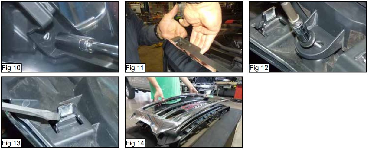
Remove four 10mm bolts from along the bottom of the factory grill shell (Fig 10). With a helper, pull up on the plastic plate along the top of the factory grille while pulling forward, the factory grille will pop loose along the top (Fig 11). Remove the factory grill from the vehicle. Place the factory grill on a workbench, on the backside of the factory grill remove eleven 7mm bolts holding the plastic air vent to the grill (Fig 12). Remove the plastic air vent. Now remove remove four 7mm bolts and unlatch sixteen plastic latches with a flat screwdriver (Fig 13). Seperate the front and back halves of the factory grill (Fig 14).
Step 2 Mesh Grille Installation
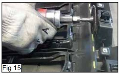
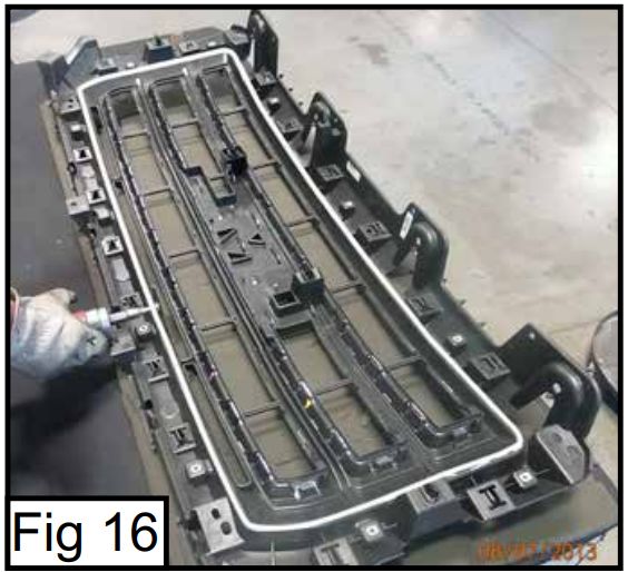
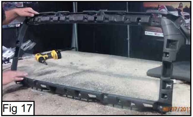
Take the black plastic back section of the factory grill, you will need to cut out the center section. On the backside of the plastic use a cutting wheel and grinder to cut along the ridge around the opening highlighted white in (Fig 15 & 16). Smooth the cut edge with the grinding wheel. The cut black section should look like (Fig 17) when fnished. Continued on page 3.
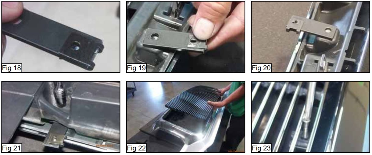
Step 2 Grille Installation
Take the black plastic back section of the factory grill and the grille shell and reassemble them into one section , just the same way they were before you separated them. Take the seven extension brackets and install the u-nuts onto them as in (Fig 18). The u-nuts install onto the end of the extension bracket that has the elongated hole, push the u-nut all the way onto the bracket. Place the seven brackets with the u-nuts installed on the black plastic on the back of the factory grille where the screw holes are located, four on the bottom and three along the top with the barb facing upward toward you (Fig 19 & 20) Place the black air vent seal onto the back of the factory grille keeping the brackets in place. Now use the factory hardware to secure the air vent plastic to the factory grille, the bolts from the factory grille will insert through the holes in the brackets, tighten. Turn over the factory grille so you are looking at the front side, insert the billet grille into the opening in the factory grille (Fig 22). Now take the seven screws from the parts bag, locate the small square tabs
on the back of the billet grille with a small hole in the center. Insert the seven screws through the billet bars and the hole in the small tabs, the screws will insert into the u-nuts on the extension brackets (Fig 23). Tighten the screws. Reinstall the bumper top pad, reinstall the completed grille assembly back onto the vehicle in the reverse order of removal. Do not forget the fenderwell hardware needs to be reinstalled as well. Installation complete.