FREE 1 to 3-Day Delivery on Orders $149+ Details
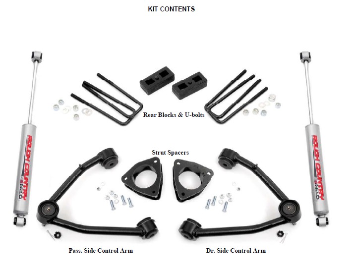
How to Install Rough Country 3.5 in. Suspension Lift Kit w/ Upper Control Arms on your Sierra
Installation Time
1 days
Tools Required
- 18MM Wrench
- 17MM Wrench
- 15MM Wrench
- 21MM Wrench
- 11MM Wrench
- 10MM Wrench
- Floor Jack
- Jack stands

Shop Parts in this Guide
FRONT INSTALLATION
1. Park the vehicle on a level surface and chock the rear wheels.
2. Jack up the front of the vehicle. Place jack stands under the frame rails and lower onto jack stands letting the front suspension hang.
3. Remove the tires and wheels. Remove the upper and lower factory skid plates using a 15mm wrench. Retain factory hardware and front skid plate for reuse. Unplug the 3 connectors powering the electric power steering.
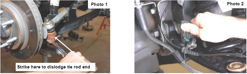
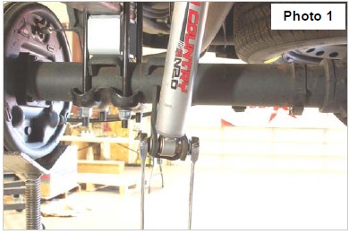
4. Using a 21mm wrench, remove the tie-rod nut as shown in Photo 1. Strike the front of the mount to dislodge the tie rod end. Remove from the knuckle.
5. Remove the sensor wire from the plastic clip. Remove the bracket from the control arm using a 10mm wrench. See Photo 2.
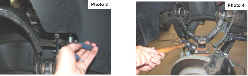
6. Remove and unplug the ABS sensor wire from the frame as shown in Photo 3.
7. Remove the upper ball joint nut using a 18mm wrench. See Photo 4. Strike the knuckle as shown to dislodge the ball joint. Separate the upper control arm from the knuckle.
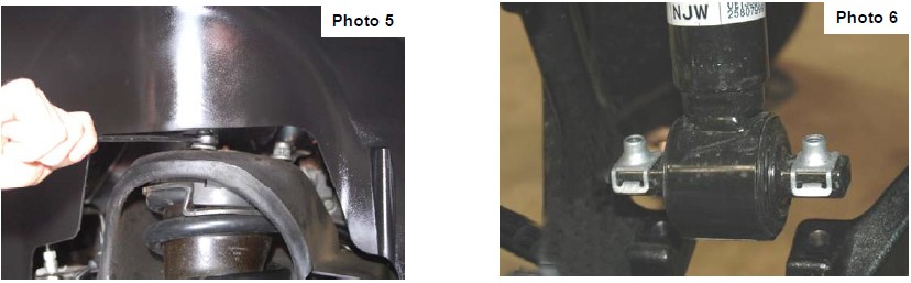
8. Using a 18mm wrench, remove the upper strut nuts as shown in Photo 5. Retain factory hardware for reuse.
9. Using a 15mm wrench, remove the 2 bolts securing the lower strut mount to the lower control arm and remove the strut
from the vehicle. Remove and discard the factory lower retainer clips. New hardware will be used. See Photo 6.
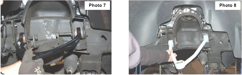
10. Mark location of alignment cams on upper control arms to allow installation of new arm to same position. Using a 21mm wrench and 21mm socket, remove the upper control arms from the vehicle. See Photo 7. Retain the hardware.
11. Install the new control arm in the factory mount as shown in Photo 12 with the factory hardware and tighten using mark made as a reference in Step 10 and using a 21mm wrench & socket.
12. Locate the supplied strut spacer and install the supplied 10mm stud extensions. Using a 17mm socket snug self clinching stud in the new spacer as shown in Photo 9.
13. Install the strut spacer on the factory strut with factory hardware and using a 18mm wrench. See Photo 10.
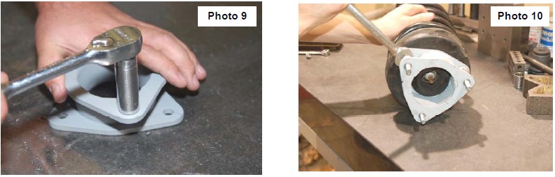
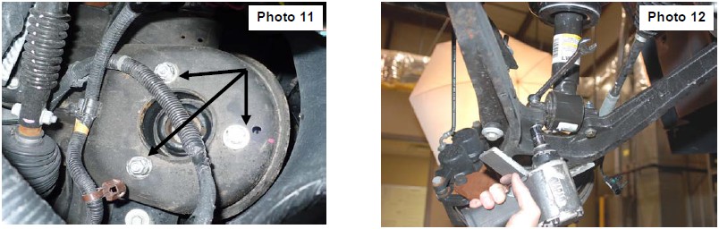
14. Install the strut assembly in the factory mount with the supplied 10mm nuts/washers &lock-washers on the upper mount. Tighten using a 17mm wrench. Flat washer must be installed on stud as shown in Photo 11.
15. Install the strut in the lower control arm using the supplied 3/8” 2 1/4” bolts /washers & nuts using a 9/16” wrench. See Photo 12. It may be necessary to jack up the lower control arm with a floor jack to align lower strut holes.
15. Reinstall the sway bar on the lower control arm using a15mm wrench.
16. Install the upper control arm / ball joint assembly onto the knuckle with the supplied and castle nuts/cotter pins. Tighten using 3/4” wrench to 50 ft/lbs. DO NOT OVER-TORQUE THE CASTLE NUT.
17. Reinstall the tie rod end into the knuckle with factory hardware and using a 21mm wench.
18. Reinstall the 3 connectors to the electric power steering.
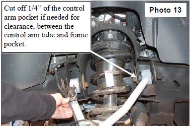
19. Install the brake line bracket on the new control arm with the supplied 1/4” lock nut / washer and using a 7/16” wrench. See Photo 13.
20. Reinstall the wheels/tires.
21. Jack up the vehicle and remove the jack stands.
22. Lower the vehicle to the ground.
REAR INSTALLATION
1. Chock the front wheels.
2. Place a floor jack under the differential and jack up the rear of the vehicle.
3. Place jack stands under the frame rails and lower onto the jack stands.
4. Remove the tires/wheels.
5. Remove the factory shock absorbers using a 21mm wrench & socket. Retain the factory hardware for reuse.
6. Remove the factory u-bolts using a 21mm socket and lower the axle using the floor jack to allow for the 1 1/2” block to be installed.
7. Install the block on the factory spring pad with the flat part of the block on the spring and the thinner end towards the front. Jack up the axle to meet the springs, making sure to align the center pin. See Photo 1.
8. With the floor jack applying slight pressure to the rear axle to keep the pin aligned, install the new supplied u-bolts and tighten in a crossing pattern, using a 7/8” socket.
9. Locate the new shock absorbers part # 658726. Install the shock absorbers in the factory mounting locations using the factory hardware, Tighten using a 21mm wrench & socket
10. Install the tires/wheels.
11. Jack up the vehicle to remove the jack stands. Remove the jack stands and lower the vehicle to the ground.
POST INSTALLATION INSTRUCTIONS
1. Lightly grease the ball joints. Do not over grease the ball joint as this could cause ball joint boot failure.
2. Have a qualified alignment center align the vehicle immediately.
3. Have headlights adjusted to proper settings.
4. Wheels must be retighten at 50 miles.
5. All kit components must be retightened at 500 miles and then every three thousand miles after installation. Periodically check hardware for tightness.
6. Install “Warning to Driver” decal on sun visor.
7. On some vehicles the front lower skirting will need to be trimmed if using certain wheel /tire combinations and with heavy offset wheels. Trim only as needed.