FREE 1 to 3-Day Delivery on Orders $149+ Details
How to Install Richmond 8.5 in. & 8.6 in. Rear Ring Gear and Pinion Set - 3.90 on your Sierra

Shop Parts in this Guide
- Richmond 8.5-Inch and 8.6-Inch Rear Axle Ring and Pinion Gear Kit; 3.90 Gear Ratio (07-13 Sierra 1500)
- EXCEL from Richmond 9.5-Inch Rear Axle Ring and Pinion Gear Kit; 3.42 Gear Ratio (07-13 Sierra 1500)
- EXCEL from Richmond 9.5-Inch Rear Axle Ring and Pinion Gear Kit; 3.73 Gear Ratio (07-13 Sierra 1500)
- EXCEL from Richmond 9.5-Inch Rear Axle Ring and Pinion Gear Kit; 4.10 Gear Ratio (07-13 Sierra 1500)
- EXCEL from Richmond 9.5-Inch Rear Axle Ring and Pinion Gear Kit; 4.56 Gear Ratio (07-13 Sierra 1500)
- EXCEL from Richmond 9.5-Inch Rear Axle Ring and Pinion Gear Kit; 4.88 Gear Ratio (07-13 Sierra 1500)
INSTRUCTIONS FOR RING AND PINION SET INSTALLATION
MOTIVE GEAR® HIGHLY RECOMMENDS THAT YOU READ THIS SET OF INSTRUCTIONS COMPLETELY BEFORE BEGINNING THE INSTALLATION OF THIS NEW GEAR SET. CORRECT INSTALLATION CAN BE THE DIFFERENCE BETWEEN A SAFE EXTENDED GEAR LIFE…OR PREMATURE FAILURE.
1. Remove the old gear set and thoroughly clean both the ring gear carrier and rear end housing with solvent. After cleaning, air dry all parts and inspect all components for damage.
2. Verify you have purchased the correct gear ratio. This can be checked by dividing ring gear tooth count by the pinion tooth count.
e.g. RING GEAR TOOTH COUNT: 35T
PINION GEAR TOOTH COUNT: 10T
35 ÷ 10 = 3.50:1
3. Used differential cases can have many thousands of miles of service. Check all threads in the case for wear. It may be necessary to chase the threads with an engineering tap to clean and align them. When changing case bolts, check to make sure they are not too long and bottom out in the ring gear.
4. Check side bearing adjusters as they are often warped and out of shape, making ring and pinion settings difficult. Replace if they are questionable.
5. Check the backside face of the ring gear for flatness. After heat-treating there may be a very small degree of taper. This may be rectified by lapping the gear with sand paper on a glass-flat surface. This will give you a more uniform pattern when setting up your new gear set.
6. Careful attention should be given to blueprinting your differential. Accurate clearance will lead to a longer life for your unit. The same care and detail as used in engine assembly should be exercised.
7. All new parts should be thoroughly cleaned before assembly and checked for damage. Pinion bearings should never be reused. Refitting the old pinion bearings to the new pinion will void any warranties. Always install new bearings.
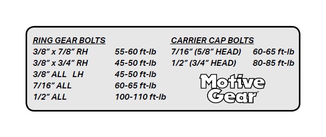
8. Examine the ring gear mounting surface for nicks or burrs which might prevent a flush mounting of the newly installed ring gear. Ring/Pinion tooth depth variations can result from a ring gear that is “cocked” on its mounting surface. If a ring gear spacer is to be used, also check it for surface imperfections. Nicks or burrs can be removed by using block-backed grit paper or a small file. Following material removal, rewash in solvent and air dry. Mount ring gear, Loctite® ring gear bolts in place and torque to factory specifications.
9. All ring gears and pinions have been “LAPPED” in sets and should never be mixed with another ring gear or pinion. Check to see that serial numbers are same on the ring gear and pinion.
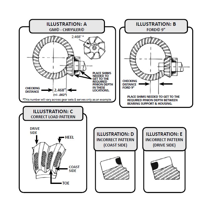
10. Each ring and pinion is pre-run and marked on the pinion face with its proper depth setting called the “Checking Distance.” This dimension is from the face of the pinion to the axle center-line. A setting tool must be used to measure the checking distance. Pinion depth is adjusted by adding or subtracting shims. Stay in /- .002” of the marked checking distance (see Illustrations ‘A’ and ‘B’).
11. Once pinion depth is achieved, using a new crush collar or preload shim pack (Dana®), set pinion bearing preload. As torque specs for setting pinion bearing preload vary widely by differential and manufacturer, please consult your factory repair manual for exact torque specifications regarding new and used bearings. Once preload is set, install the seal and Loctite® the pinion nut.
12. Once the pinion gear is installed, position ring gear and carrier into housing to check backlash. Each ring gear and pinion is developed to run at .007” to .009” backlash for street gear sets.
13. Adjustments for backlash are done by spanner rings in the housing or shim packs behind the carrier bearing cups (GM® or Dana®). Always be sure carrier bearings are preloaded. The carrier should not fall out of the housing, but should have to be “tapped” in during final installation. Replace bearing caps and torque to factory specifications.
14. You are now ready to verify the tooth contact pattern. A gear marking compound should be used. Paint gear teeth with marking compound in several spots and rotate ring gear several revolutions. A tooth contact pattern will appear and should be similar to the pattern shown in Illustration ‘C’. If the pattern is not in the approximate position shown, reset pinion depth and backlash to correct pattern. Pinion shims usually must be moved in .003” increments to notice a pattern change. If a pattern is heavy toe, subtract shims (see Illustration ‘D’). If a pattern is heavy heel, add shims (see Illustration ‘E’).
15. Fill the case with the required amount of FRESH 80W-90 gear lube. (DO NOT USE “USED” gear lube - no matter how low the mileage and time on the oil). Maintain the proper level after the road test as this may change fluid level. Add as necessary. Proper maintenance is a must to ensure your safety, as well as protect the working life of your gear set.
16. Make sure oil vent is not blocked in rear end housing.
SPECIAL NOTE: IN EXTREME CONDITIONS WE STRONGLY RECOMMEND A NEW DIFFERENTIAL COVER THAT HAS AN EXTENDED OIL CAPACITY FOR NON-REMOVEABLE CARRIER-TYPE REAR ENDS.
BREAK-IN PERIOD REQUIRED !
A new ring and pinion installation, especially a high numeric ratio gear set, can cause an excessive heat buildup in the rear end and cause softening of the gear teeth and bearings if a break-in is not performed.
Street vehicles should be driven at normal street driving speed for approximately 10 miles, then stop and let cool for 30 minutes. Do this 2 to 3 times. Towing vehicles need approximately 200 to 300 miles of normal street driving without a trailer before being used for towing.
On circle track race cars make approximately 6 to 8 laps at slow speed, then let cool for 30 minutes. Make 6 to 8 more laps at slow speed, then 2 to 3 laps at full speed, then let cool again for 30 minutes.
Drag cars need only an initial run-in since they are driven short distances and heat is not normally a problem with proper lube and backlash allowance.
NOTE: If after the above break-in is performed & overheating of the rear end is suspected, repeat the final portion of the relevent break-in procedure.
TORQUE SPECIFICATIONS