FREE 1 to 3-Day Delivery on Orders $149+ Details
How to Install Rough Country 3.5 in. MagneRide Suspension Lift Kit on your Sierra
Installation Time
5 hours
Tools Required
- 18MM Wrench
- 15MM Wrench
- 21MM Wrench
- 11MM Wrench
- 10MM Wrench
- Floor Jack
- Jack stands
- Strut Compressor
- Die Grinder

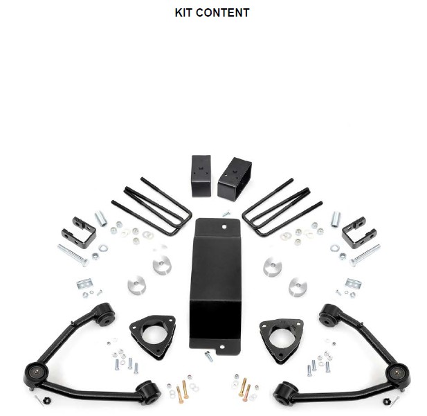
Shop Parts in this Guide
FRONT INSTALLATION
1. Park the vehicle on a level surface and chock the rear wheels.
2. Jack up the front of the vehicle. Place jack stands under the frame rails and lower onto jack stands letting the front sus-pension hang.
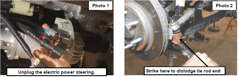
3. Remove the tires and wheels. Remove the 6 bolts holding the factory skid plate using a 15mm socket. Unplug the three connectors going to the electric power steering. See Photo 1.
4. Retain factory hardware and front skid plate for reuse.
5. Using a 21mm wrench, remove the tie-rod nut as shown in Photo 2. Strike the front of the mount to dislodge the tie rod end. Remove from the knuckle.
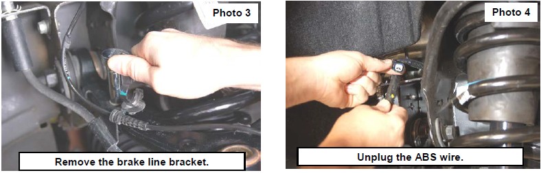
6. Remove the sensor wire from the plastic clip. Remove the brake line bracket from the control arm using a 10mm wrench. See Photo 3. Using a 10mm wrench disconnect the Magnaride linkage from the upper control arm.
7. Remove and unplug the ABS sensor wire from the frame as shown in Photo 4.
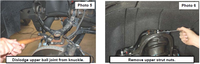
8. Remove sway bar link with 15mm socket and wrench. Place jack stand under knuckle for support and then remove up-per ball joint nut using a 18mm wrench. See Photo 5. Strike the knuckle as shown to dislodge the ball joint. Separate the upper control arm from the knuckle.
9. Using a 18mm wrench, remove the upper strut nuts as shown in Photo 6. Retain factory hardware for reuse.
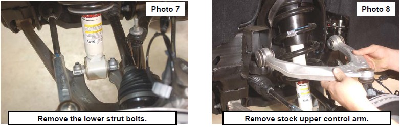
10. Using a 15mm wrench, remove the 2 bolts securing the lower strut mount to the lower control arm and remove the strut from the vehicle. See Photo 7.
11. Mark location of alignment cams on upper control arms to allow installation of new arm to same position. Using a 21mm wrench and 21mm socket, remove the upper control arms from the vehicle. See Photo 8. Retain the hardware.
12. Using a 18mm socket and wrench remove the four bolts holding in the factory cross member. Retain factory hardware.
13. Use a jack stand to support the front diff. Remove the 4 bolts holding the diff mounts to the frame with a 15mm and 18mm wrench.
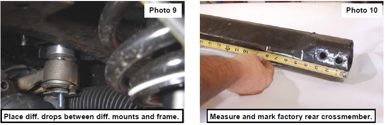
14. Lower the jack stand and pull down on the front of the diff to allow enough room to slide the two 1” aluminum diff drop spacers into place. Use the supplied 7/16” x 4.5” bolts, lock washers, and nuts from 275BAG6. Repeat this process to install 1” spacers in the rear diff mounts, as well. Tighten using 16mm and 18mm socket and wrench. Tighten with a 16mm and 18mm socket and wrench. See Photo 9.
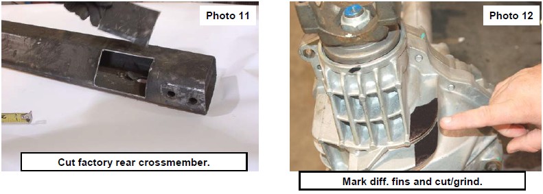
15. On the driver side of the factory cross member measure from the end of the tube and make marks at 4.5” and 8” on the front side as shown in Photo 11. Measure 1/4” for the bottom, and 2” from the back side and mark.
16. Using a die grinder and cut across the marks as shown in Photo 11.
17. Using a die grinder, grind the cooling fins on the diff. Hold the cross member into place and check clearance between the cross member and front diff. See Photo 12.
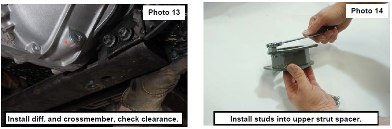
18. Insert factory hardware into the stock cross member and tighten with a 18mm socket and wrench. See Photo 13.
19. Using the supplied 10mm studs place each stud into the smaller sized holes in the strut spacer facing upward. Use the supplied sleeve to slide over each stud to act as a spacer allowing you to pull the stud through the hole with the 10mm nut and a 17mm wrench, locking the stud into place. Remove sleeve and repeat on the other five studs. See Photo 14.
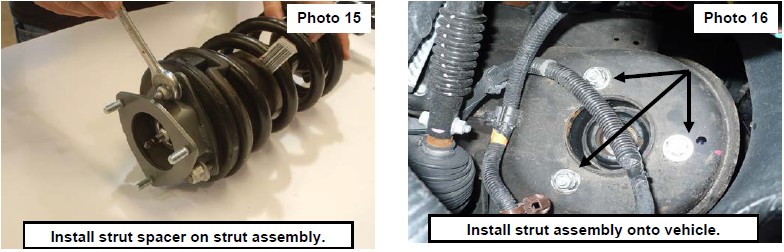
20. Place the strut spacer on top of the stud and tighten using factory hardware and a 18mm wrench. See Photo 15.
21. Install the strut assembly in the factory mount with the supplied 10mm nuts/washers &lock-washers on the upper mount. Tighten using a 17mm wrench. Note: Locking washer must be installed between nut and regular washer on studs. See Photo 16.
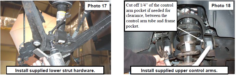
22. Install the strut in the lower control arm using supplied 3/8” x 2.25” bolts, washers, and nuts. See Photo 17. It may be necessary to jack up the lower control arm with a floor jack to align lower strut holes.
23. Reinstall the sway bar on the lower control arm using a15mm wrench.
24. Install the supplied control arm with factory hardware. Reinstall the knuckle to the upper control arm with the supplied castle nuts/cotter pins. Tighten using 3/4” wrench to 50 ft/lbs. DO NOT OVER-TORQUE THE CASTLE NUT. Reinstall the tie rod end into the knuckle with factory hardware and using a 21mm wench.
25. Install the brake line bracket on the new control arm with the supplied 1/4” lock nut / washer and using a 7/16” wrench. See Photo 18. Driver side shown.
26. Reconnect the ABS wire that was disconnected.
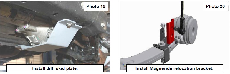
27. Locate and install the new lower skid plate below the differential in the factory location with the factor hardware and us-ing a 15mm wrench. See Photo 19.
28. Using the supplied bracket and 6mm hardware, attach the Magneride linkage as shown in Photo 20. Tighten using a 10mm wrench.
29. Reconnect the three connectors going to the electric power steering.
30. Reinstall the wheels/tires.
31. Jack up the vehicle and remove the jack stands.
32. Lower the vehicle to the ground.
REAR INSTALLATION
1. Chock the front wheels.
2. Place a floor jack under the differential and jack up the rear of the vehicle.
3. Place jack stands under the frame rails and lower onto the jack stands.
4. Remove the tires/wheels.
5. Remove the factory shock absorbers using a 21mm wrench & socket. Retain the factory hardware for reuse.
6. Remove the factory u-bolts using a 21mm socket, then remove the factory blocks.
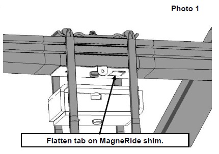
4. Remove the MagneRide shim and flatten tab. Reinstall on bottom of leaf pack. See Photo 1.
5. Lower the axle using the floor jack to allow for the new 3” block to be installed. Larger end to the rear of the truck.
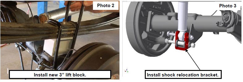
6. Install the block on the factory spring pad with the flat part of the block on the spring and the thinner end towards the front. Jack up the axle to meet the springs, making sure to align the center pin. See Photo 2.
7. With the floor jack applying slight pressure to the rear axle to keep the pin aligned, install the new supplied u-bolts and tighten in a crossing pattern, using a 7/8” socket.
8. Using the supplied sleeves, bolts, and washers from 1189BAG2, install the shock relocation brackets. See Photo 3.
9. Install the tires/wheels.
10. Jack up the vehicle to remove the jack stands. Remove the jack stands and lower the vehicle to the ground.
POST INSTALLATION INSTRUCTIONS
1. Lightly grease the ball joints. Do not over grease the ball joint as this could cause ball joint boot failure.
2. Have a qualified alignment center align the vehicle immediately.
3. Have headlights adjusted to proper settings.
4. Wheels must be retighten at 50 miles.
5. All kit components must be retightened at 500 miles and then every three thousand miles after installation. Periodically check hardware for tightness.
6. Install “Warning to Driver” decal on sun visor.
7. On some vehicles the front lower skirting will need to be trimmed if using certain wheel /tire combinations and with heavy offset wheels. Trim only as needed.