FREE 1 to 3-Day Delivery on Orders $149+ Details
How to Install Rough Country 3.25 in. Suspension & Body Lift Kit on your Sierra
Installation Time
3 hours
Tools Required
- 18mm Wrench
- 15mm Socket
- 15mm Wrench
- 17mm Wrench
- 21mm Wrench
- 7/32 Allen Wrench
- Flat Screwdriver
- Hammer
- 8mm Socket
- 10mm Socket / Wrench
- 11mm Socket / Wrench
- 12mm Socket / Wrench
- 13mm Socket / Wrench
- 14mm Socket / Wrench
- 15mm Socket / Wrench
- 16mm Socket / Wrench
- 18mm Socket / Wrench
- 19mm Socket / Wrench
- 21mm Socket / Wrench
- 22mm Socket / Wrench
- Hand Grinder
- #15, #40, & #45 Torx bit
- Jack
- Jack Stands
- Wood Blocks (2x4)
- Pliers
- Phillips Screwdriver
- Drill Motor
- 1/2” Drill Bit
- Reciprocating Saw

Shop Parts in this Guide
INSTALLATION INSTRUCTIONS
1. Jack up the front of the vehicle and support the vehicle with jack stands, so that the front wheels are off the ground
2. Remove the front tires/wheels., using a 21mm deep well socket
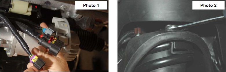
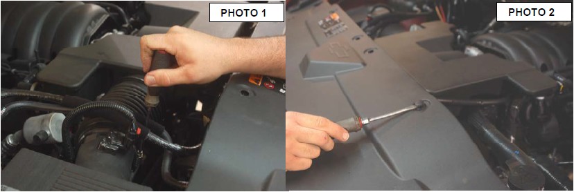
3. Unplug the three connectors going to the electric power steering. See Photo 1.
4. Using a 18mm wrench loosen the upper strut bolts. It is not necessary to remove nuts. See Photo 2.
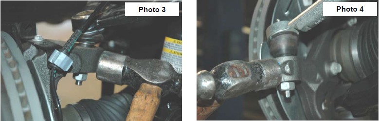
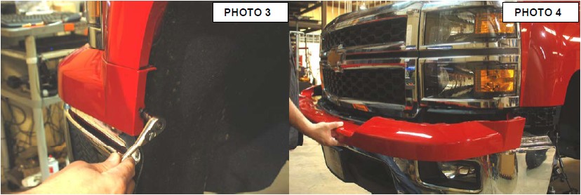
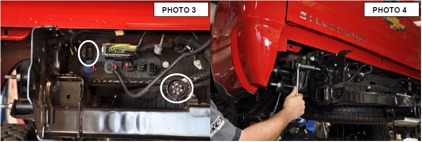
5. Place jack stand under the knuckle for support. Remove upper ball joint nut, using a 18mm wrench. Using a hammer hit the knuckle as shown to allow the ball joint to separate from the knuckle. See Photo 3. Do not allow the knuckle to pull out far enough that it pulls the shaft out of the differential.
6. Using a 21mm wrench remove the nut from the steering linkage. Using a hammer hit on the front of the knuckle as shown, where the steering linkage is connected and remove from knuckle. Push linkage forward to make room for installation. Retain factory hardware. See Photo 4.
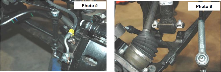
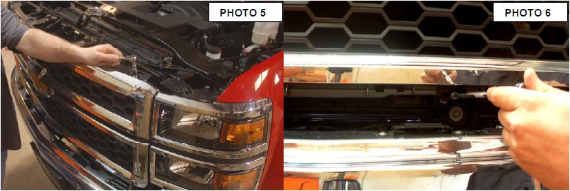
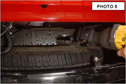
6. Remove the sway bar nut and bushings using a 15mm wrench, and 15mm socket. Retain factory hardware. See Photo 5
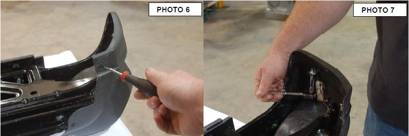
7. Using a 15mm wrench remove the bolts from the bottom strut mount. See Photo 6.
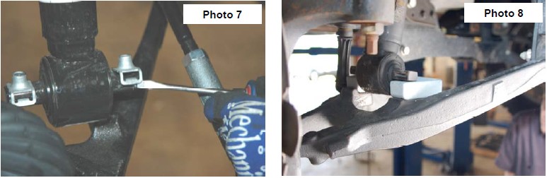
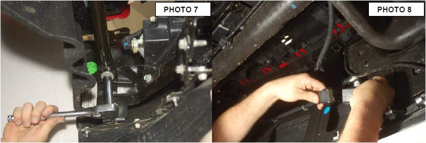
8. Remove the bolt clips from the bottom of the strut using a flat screw driver. See Photo 7
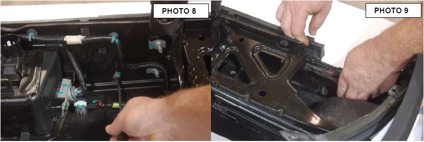
9. Place strut spacer under the lower strut mount and align holes. See Photo 8.
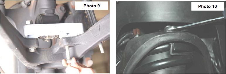
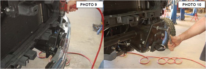
10. Install the new 10mm bolts, washers and nuts provided in the kit. Install bolts with the head going down as shown in Photo 9. Tighten to 30-35 ft/lbs. Do not over-tighten the bolts. You may have to move the knuckle to one side to allow room to install the bolt by the axle shaft.
11. Tighten the bolt using a 17mm wrench, and a 16mm wrench for the nut.
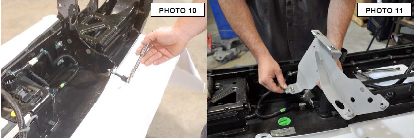
12. Using a 18mm wrench tighten the upper strut nuts, torque to factory specs See Photo 10.
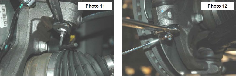
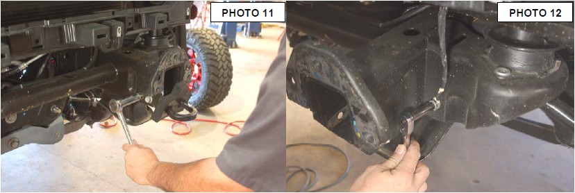
13. Raise the lower control arm and connect the upper ball joint on the upper control arm to the spindle. Using a 18mm wrench, torque to manufacturer specs. If ball joint turns while tightening, use a 7/32”allen wrench to hold the ball joint. See Photo 11.
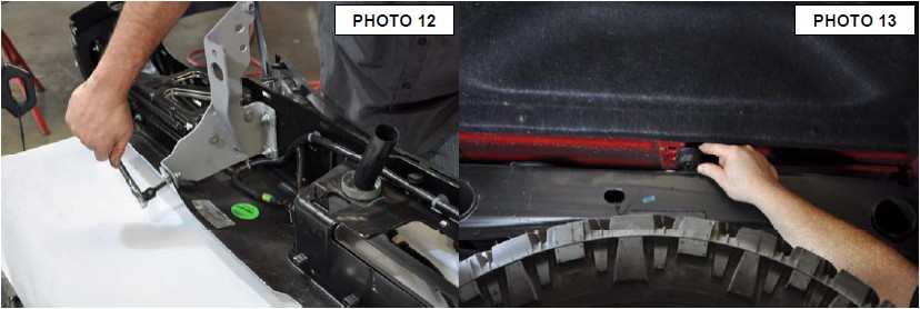
14. Reinstall the steering linkage nut using a 21mm wrench. If ball joint turns while tightening, use a 10mm wrench to hold the bottom of the tie rod. See Photo 12.
15. Repeat steps 4-14 on opposite side of vehicle
16. Using a 15mm wrench, reinstall sway bar bushings and nut using factory hardware. Torque to factory specs. Plug the three connectors back into the electric power steering.
17. Install the wheels / tires, using a 21mm deep well socket.
18. Jack up the vehicle and remove the jack stands. Lower the vehicle to the floor and torque all bolts to factory specifications.
19. Using an certified alignment professional, have an alignment done to factory specifications.
POST INSTALLATION
1. Check all fasteners for proper torque. Check to ensure there is adequate clearance between all rotating, mobile, fixed and heated members. Check steering for interference and proper working order. Test brake system.
2. Perform steering sweep. The distance between the tire sidewall and the brake hose must be checked closely. Cycle the steering from full turn to full turn to check for clearance. Failure to perform inspections may result in component failure.
3. Re torque all fasteners after 500 miles. Visually inspect components and re torque fasteners during routine vehicle service.
4. Readjust headlights to proper settings.
MAINTENANCE INFORMATION
It is the ultimate buyers responsibility to have all bolts/nuts checked for tightness after the first 500 miles and then every 1000 miles. Wheel alignment steering system, suspension and driveline systems must be inspected by a qualified professional mechanic at least every 3000 miles.
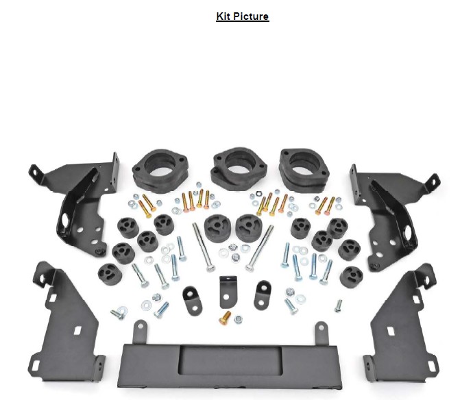
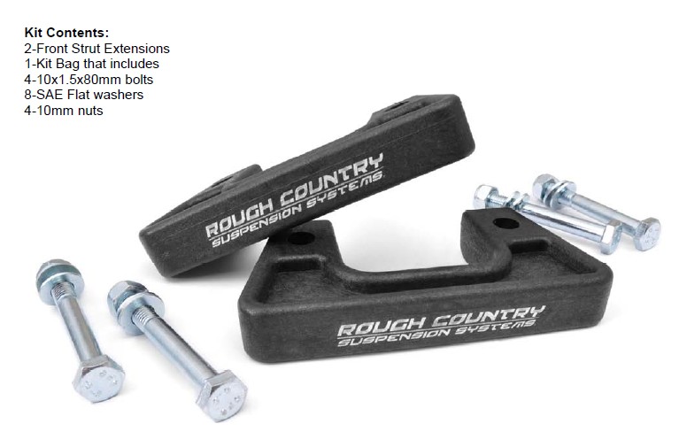
KIT CONTENTS
FRONT INSTALLATION INSTRUCTIONS
1. Disconnect battery using a10mm socket
2. Using a screwdriver disconnect the air filter inlet hose from air box. See Photo 1. Lock the steering wheel and mark upper and lower steering shaft. Remove steering shaft from rack and pinion using a 11mm socket.
3. Remove the ten plastic clips from the radiator bezel using a screwdriver. See Photo 2.
4. Remove the painted bumper bezel from truck using a 7mm socket, remove the two bolts on both side. See Photo 3.
5. Unclip the painted bumper bezel from the grill. There are six clips behind the bumper. Pull the sides of bumper bezel out then pull back to remove. See Photo 4. This may take two people .
6. Remove the 8 bolts holding the front grill on using a 10mm socket. There are 4 bolts on top See Photo 5 and 4 bolts on bottom See Photo 6 of the grill. There are two clips on each side. Pull straight out to release clips.
7. Remove the side bumper support bracket using a 15mm socket . See Photo 7.
8. Unplug the fog lights and wiring harness from bumper. See Photo 8.
9. Use a 18mm socket to remove the four bolts holding the bumper on to the frame then remove bumper. See Photo 9.
10. Remove front bumper brackets using a 15mm socket. See Photo 10.
11. Then remove tow hooks using a 18mm socket and wrench. See Photo 11.
12. Using a 10mm socket remove the ground wires from frame. Two of the ground wires are on both front body mounts. See Photo 12.
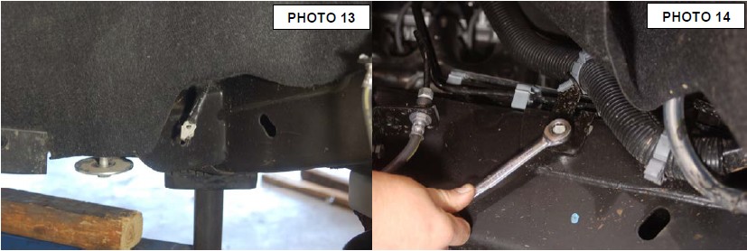
13. The other ground wire is on passenger side body mount behind the tire. See Photo 13.
14. Remove the O2 sensor wire clip from frame just above passenger side body mount. On driver side remove the wiring loom bracket using a 13mm socket. See Photo 14. Remove the wire clips from the top of strut bolts.
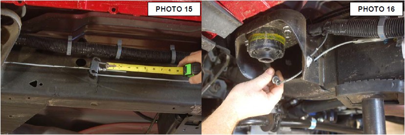
15. Measure the emergency brake cable adjustment bolt from back of nut to the end of threads and record this measurement for later use. ( Should be about 2.5” ). See Photo 15.
16. Then adjust bolt to allow slack so the brake cable can be disconnected. Then release the metal clips holding the emergency cable to frame on body mount. See Photo 16.
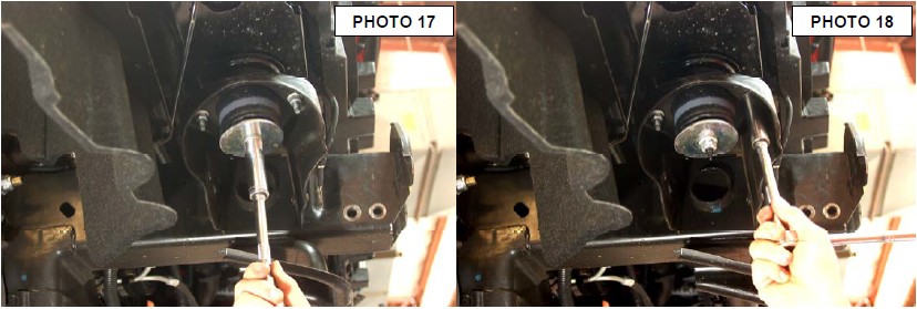
17. Loosen the front body mount bolts using a 18mm socket and a 21mm on the other body mount bolts. See Photo 17. Remove the nuts from the body bushing using a 15mm socket. See Photo 18. Only remove the bolt on one side at a time. Lift the body off of frame just enough to remove body bushing. Look an make sure no other wires or brake lines are being stretched. Front body mount bolt must come out from the top.
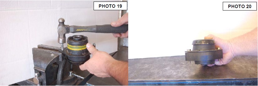
18. Once the bushing is out knock the two studs out using a hammer and vise. See Photo 19. Replace the two stud with the supplied 3/8” x 2.25” bolts, washers, and nuts. Install cab body puck on body bushing and place on truck. See Photo 20.
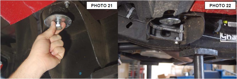
19. Install the 1.25” x 3” round body puck onto of rear cab body bushing. Use a 14mm socket and wrench to tighten new bolt. Lower body onto body bushing and install body bolts but do not tighten at this time. Install a new rear cab bolt 14mm x 140mm. See Photo 21. Repeat step for other side. Make sure the wiring does not get pinch under the flag bolt on the two front body mounts while installing. Once all body puck are in tighten all bolts using 19mm for front body bolts 21mm for middle bolts and 22mm for rear cab bolts.
20. Install emergency brake line bracket using the supplied 1/2” x 1” bolt, washer, and nut. Use a 19mm socket and wrench to tighten. See Photo 22. Reconnect the emergency brake cable. Take a 1/4 off inch off the original measurement taken adjust the parking brake cable to around 2.25” from the back of the nut to the end of the threads.
21. Reinstall ground wires and O2 sensor clip back onto frame using 10mm socket. Ground wire on passenger side body mount be hide tire will need a clip removed to get slack in wire.
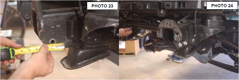
22. On the front frame horns measure the tow hook mounting hole on the side with only one hole 1 1/2” back and 1 3/16” up from bottom of frame. See Photo 23. Mark the area and drill a new hole for the tow hooks using a 1/2 drill. Flip the tow hooks and install bolts. Tighten using 18mm socket. See Photo 24.
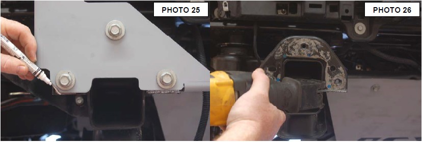
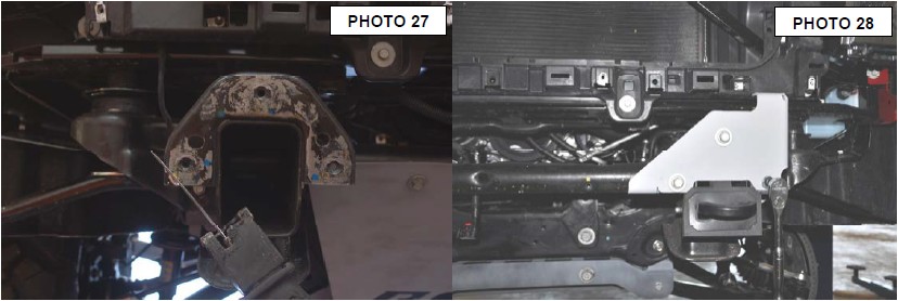
23. Install new front bumper brackets using stock hardware, push up on the bracket when you tighten the bolts. Using the bracket for a template mark and remove the lower inside of frame horn and out side corners. Use a sawzall or cut off wheel to remove the material. See Photo 25, 26, and 27.
24. After cutting reinstall the bumper bracket with factory bolts and the supplied 10mm x 30mm button head bolt and washer for the outside hole. Pull up on the bracket and tighten bracket using a 15mm socket and a 6mm allen wrench. See Photo 28.
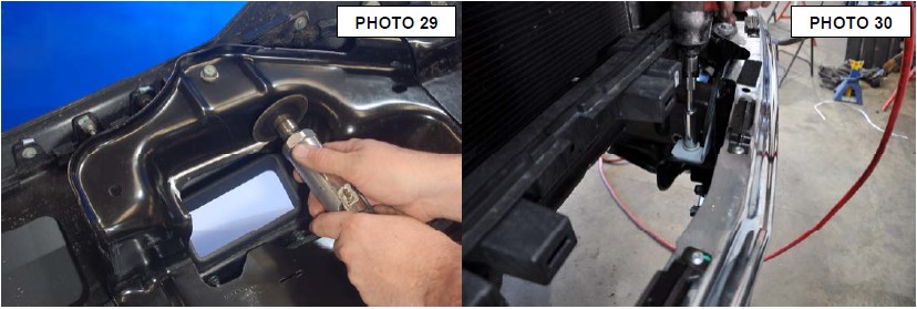
25. On the inside of the front bumper where the tow hooks holes are measure 1/4 down on the inner bumper bracket and cut even with the sides of the holes. See Photo 29.
26. Install front bumper using stock hardware with the supplied 12mm nuts. Use a 18mm socket and wrench to tighten bumper bolts. See Photo 30.
27. Reinstall front grill using stock hardware and a 10mm socket to tighten all 8 bolts. Reinstall painted bumper bezel using stock hardware. Reinstall steering shaft using a 15mm. Reconnect air inlet hose to air box. Reinstall radiator bezel using the stock plastic clips.
28. Tighten the side bumper support bracket using a 15mm socket. Push the bracket up while tightening the bolts
BED/REAR BUMPER INSTALLATION INSTRUCTIONS
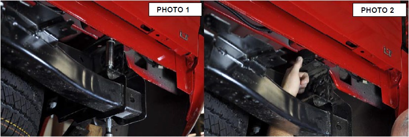
**Note** The bumper is removed in the first three pictures to help show locations for the bolts and electrical plugs. The bumper is not removed until step 3.
1. Loosen the 8 bolts holding the bed on using a 18mm socket. See Photo 1. Remove the six rear bolts on bed leaving the front bolts near cab in but loose. Lift the rear of bed up just enough to place one of the body puck between frame and bed. This is done so rear bumper can be removed. See Photo 2.
2. Unplug the rear bumper wiring from the junction box on the frame and unplug the 7 way connector from bumper. See Photo 3.
3. With the license plate remove reach be hide the bumper and remove the two bolts using a 13mm wrench. One is on the left and one on the right. Using a 15mm, 18mm and a 21mm socket remove bumper bolts. See Photo 4. ( note bumper was remove to show better picture). Remove bumper and place on a clean surface.
4. Mark and cut the tap off the frame for the spare tire tube. Cut straight across the top making the top flat with no ridge. See Photo 5.
5. Using a torx 15 to remove lower bumper screws from the plastic bumper cover. See Photo 6.
6. Using a 7mm socket remove the screws from the inside of bumper. See Photo 7.
7. Using a screwdriver remove the metal clips from the plastic bumper cover. There will be five metal clips to be removed. See Photo 8.
8. Using a pair of pliers to release the plastic clips holding the bumper cover to metal part of the bumper, while pulling on the bumper cover to separate. Only remove enough to allow removal of bumper mounting bracket. See Photo 9.
9. Using a 45 torx remove the five bolts holding the bumper mounting bracket. See Photo 10.
10. Remove the threaded body clip from the stock bumper brackets and place clips in the same area on the new supplied bumper brackets. See Photo 11.
11. Install new bumper brackets using stock hardware and a 40 torx to tighten. See Photo 12.
12. Reassemble rear bumper
13. Remove the body puck from the rear of bed that was place to help remove the bumper and install the bed bolts on one side of the truck to hold the bed in place while installing bed pucks. Hand tighten bolts. Remove the bolt from front of bed that was left loose earlier.
14. Lift one side of the bed at a time and install the five 1 1/4 body pucks. See Photo 13. Use the supplied 12mm bolts, washers. Repeat this step for other side. Use a 19mm socket to tighten bed bolts
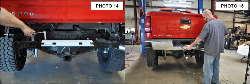
15. Install rear bumper step support bracket using the stock hardware. Use a 13mm socket to tighten. See Photo 14.
16. Reinstall rear bumper using stock hardware. See Photo 15. Make sure spare tire tube go back in bumper correctly.
17. Plug in the 7 way connector and bumper wiring. Tighten bumper using a 15mm, 18mm and a 21mm sockets. Make sure bumper is level
18. Reconnect battery