FREE 1 to 3-Day Delivery on Orders $149+ Details
How to Install Airaid MXP Series Cold Air Intake w/ SynthaFlow Oiled Filter on your Dodge Ram

Shop Parts in this Guide
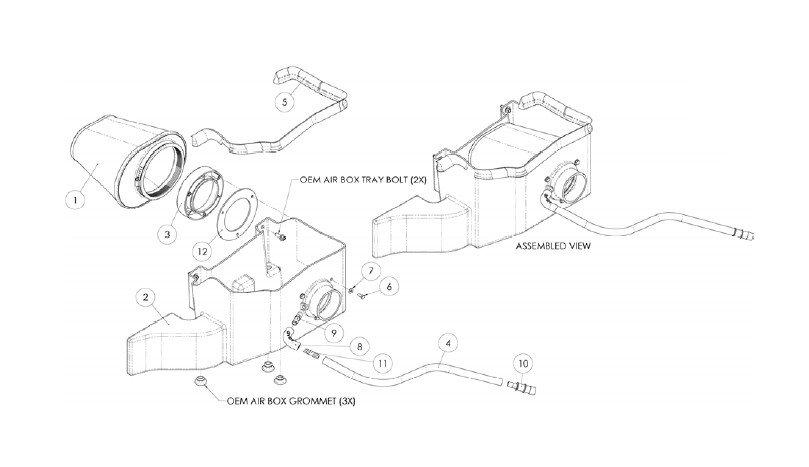
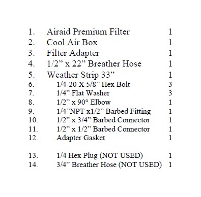
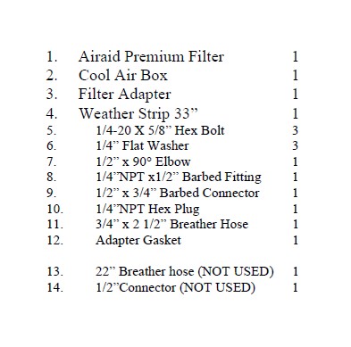
Component Identification
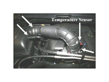
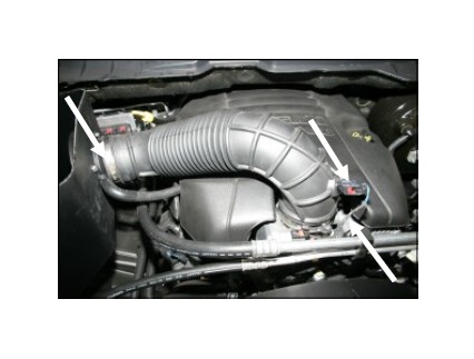
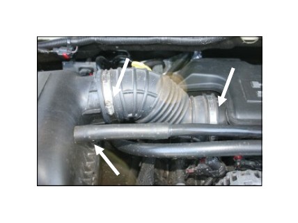
1. Disconnect the negative battery cable! Locate the temperature sensor on the air intake tube, slide the red tab, squeeze the black tab on the electrical connector, and then disconnect the temperature sensor from the air intake tube. Disconnect the crankcase breather tube from the air filter box. Loosen one hose clamp at each end of the air intake tube and remove it from the vehicle.
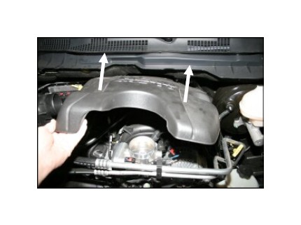
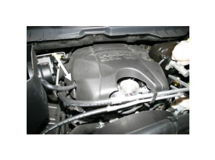
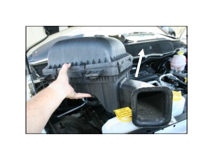
2. Lift up the front of the engine beauty cover, and then pull it towards you to remove it from the vehicle. It is only held in position by rubber grommets.
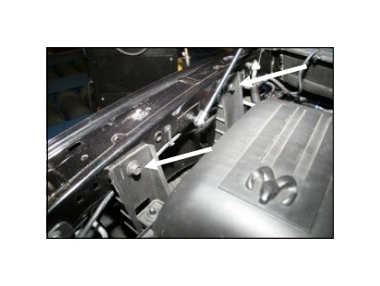
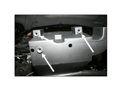
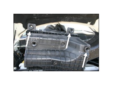
3. Using a 13mm socket, remove the two bolts that hold the air cleaner mount to the inside right fender. Save them for reinstallation in step #9.
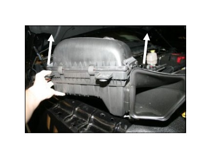
4. Rock the airbox back and forth as you are lifting it straight up to remove it from the vehicle. It is only held in by grommets.
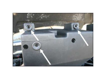
5. Remove and save three grommets from the bottom of the factory airbox. They will be reused in step #6.
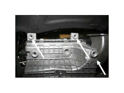
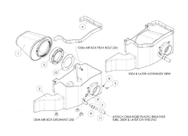
6. Install the three grommets removed in step #5 into the bottom of the Airaid Cool Air Box (CAB) (#2) at the locations shown here.
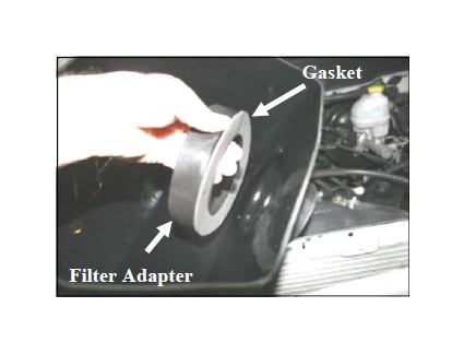
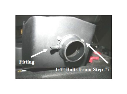
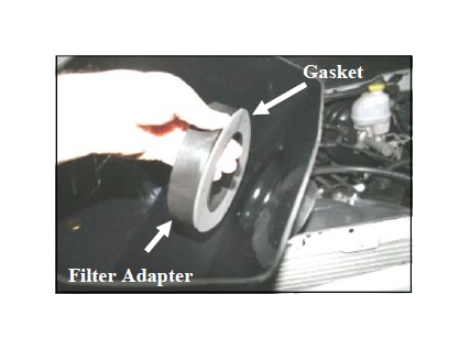
7. Install the adapter gasket (#12) and filter adapter (#3) into the CAB using three 1/4-20 x 5/8” bolts (#6) and flat washers (#7) as shown. Refer to the line drawing above for reference.
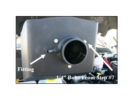
8. Install the 1/4” NPT x 1/2” barbed fitting (#9) into the filter adapter as shown.
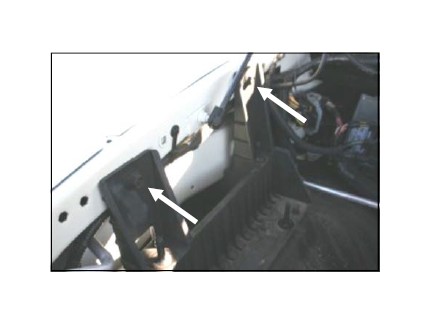
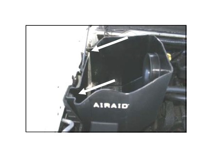
9. Install the CAB into the vehicle by aligning the grommets over the locating pins on the factory airbox mount. Reinstall the factory bolts into the fender that were removed in step #3.
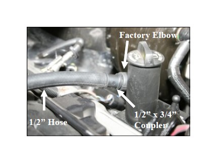
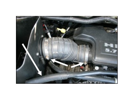
10. Install the supplied 1/2” x 3/4” plastic reducing coupler (#10), into the factory rubber elbow next to the oil fill neck as shown, and then connect the supplied 1/2” x 22” hose (#4) to the coupler.
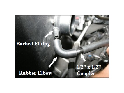
11. Install the supplied 1/2” x 1/2” plastic coupler (#11) into the 1/2” hose from step #10. Next connect the 1/2” rubber elbow (#8) between the 1/2” connector and the barbed fitting on the filter adapter.
12. Reinstall the factory beauty cover making sure that the grommets are aligned with the grommet posts and that the crankcase breather hose is aligned in the slot on the side of the cover.
13. Reinstall the factory air intake tube. Reconnect the electrical connector to the temperature sensor, and then tighten both hose clamps.
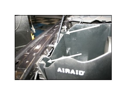
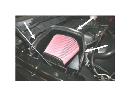
14. Install the Airaid Premium Filter (#1) onto the filter adapter and tighten the clamp. Next install the weather strip (#5) on the top of the CAB as shown. (Hint: Start at one end of the CAB and work your way towards the other end.)
15. Double check your work! Make sure there is no foreign material in the intake path. Make sure all clamps, hoses, fasteners, and wiring connections are tight.
16. Reconnect the negative battery
cable!
Discard parts # 13 and 14. They
are not used on this application.
Component Identification
1. Disconnect the negative battery cable! Loosen the two hose clamps on the flexible intake tube, one at the airbox lid and one at the resonator. Slide the flexible tube off of the lid and the resonator and remove it from the vehicle.
2004-and later Models: Disconnect the crankcase breather hose that attaches to the factory air-
2. Rock the airbox back and forth as you are lifting it straight up to remove it from the vehicle. It is only held in by grommets.
3. Remove and save three grommets from the bottom of the factory airbox. They will be reused in step #4.
4. Install the three grommets removed in step # 3 into the bottom of the Airaid Cool Air Box (CAB) (#2) at the locations shown here.
5. Using a 13mm socket, remove the two bolts that hold the airbox mount to the inside right fender. Save them for reinstallation in step #8.
6. Install the adapter gasket (#12) and filter adapter (#3) into the CAB using three 1/4-20 x 5/8” bolts (#5) and flat washers (#6) as shown. Refer to the line drawing above for reference.
7. Install the 1/4” NPT x 1/2” barbed fitting (#8) into the filter adapter as shown.
2003 Models: Install the 1/4”NPT plug (#10) in place of the barbed fitting.
8. Install the CAB into the vehicle by aligning the grommets over the locating pins on the factory airbox mount. Reinstall the factory bolts thru the CAB and into the fender that were removed in step #4.
9. Reinstall the factory air intake tube and tighten the two hose clamps. Remove the rubber hose from the end of the factory crankcase breather tube.
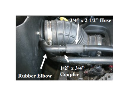
10. Install the supplied 3/4” x 2 1/2” hose (#11) onto the factory crankcase breather tube, and then insert the 1/2” x 3/4” barbed connector (#9) into the 3/4” hose. Next connect the 1/2” rubber elbow (#7) from the 1/2” barbed fitting on the filter adapter to the 1/2” x 3/4” connector. See the line drawing on the front page for reference.
2004-and later Models: Inser t the 1/2” x 3/4” connector into the factory breather hose and then install the rubber elbow between the two 1/2” barbed fittings, similar to what is shown above.
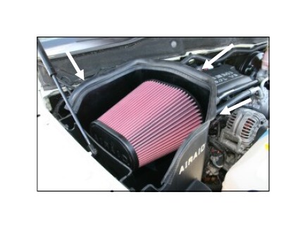
11. Install the Airaid Premium Filter (#1) onto the filter adapter and tighten the clamp. Next install the weather strip (#4) on the top of the CAB as shown. (Hint: Start at one end of the CAB and work your way towards the other end.)
12. Double check your work!
Make sure there is no foreign material in the intake path. Make sure all clamps, hoses, fasteners, and wiring connections are tight.
13. Reconnect the negative battery cable!
Discard parts # 13 and 14. They are not used on this application.