FREE 1 to 3-Day Delivery on Orders $149+ Details
How to Install Husky WeatherBeater Center Hump Floor Liner - Tan on your F-150
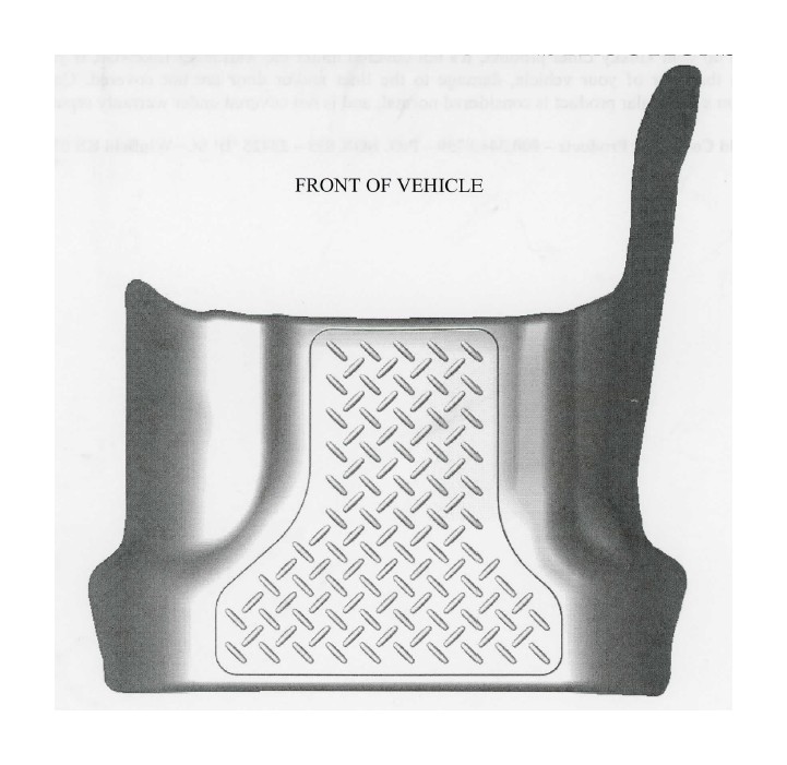
Thank you for selecting a WeatherBeater® Floor Liner from Winfield Consumer Products. Your new center hump liner is custom molded to fit your F150 SuperCrew and Super Cab trucks. The liner is made to take the place of your factory floor mat. For correct fit, it is necessary to remove the factory floor mats before installing your new floor liner. However, do not remove the factory-installed carpeting.
Your liner is made from an engineering resin that is lightweight and extremely tough and durable. The easiest way to clean your liner is with a damp cloth or sponge. If using a cleaner, 4090 or Glass Plus® work well. Use of Armor All®, Son-of-a-Gun® or similar items is discouraged as these products make the liner slick.
FORD F150 SUPERCREW AND SUPER CAB TRUCK CENTER HUMP LINER INSTALLATION INSTRUCTIONS