FREE 1 to 3-Day Delivery on Orders $149+ Details
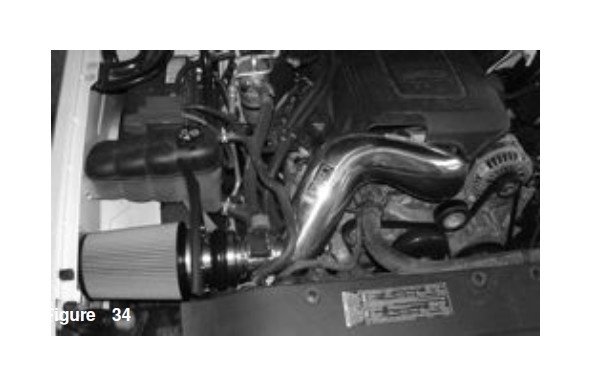
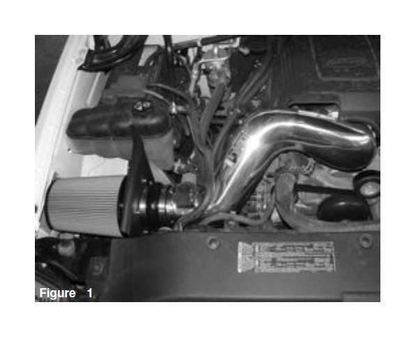
How to Install Injen Power-Flow Cold Air Intake w/ Heat Shield - Polished on your Sierra
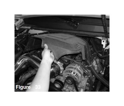
Pull the engine cover off the intake manifold.
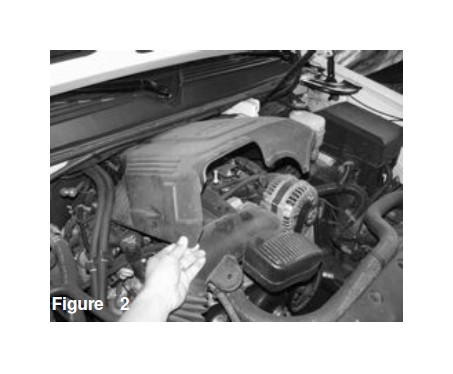
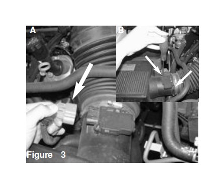
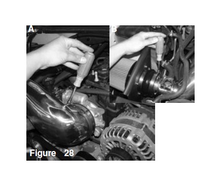
Figure 3 Figure 4 Figure 5 Figure 6 Figure 7 Figure 8 Figure 9 Figure 10 Figure 11 Figure 12 Figure 13 Figure A: Unplug the the harness off the MAF sensor Figure B: Us a T15 Torx bit and remove the two screws on the MAF sensor
Pull the MAF sensor out of the factory air box assembly
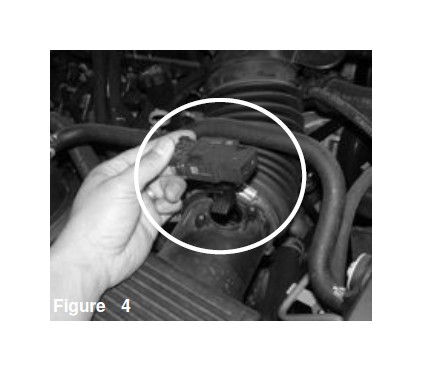
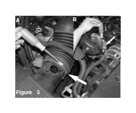
Figure A: Us a 8mm nut driver and loosen the clamp on the intake air duct from the air box assembly Figure B: Now loosen the ckamp on thethrottlebody end of the air duct.
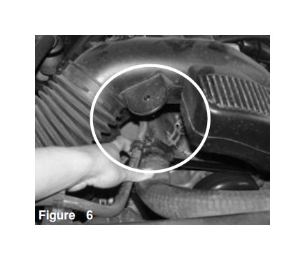
Unclip the coolant lines underneath the air duct from the tab
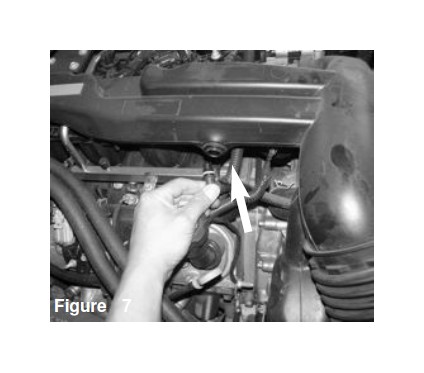
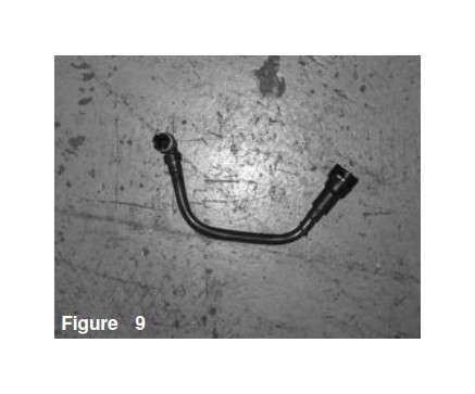
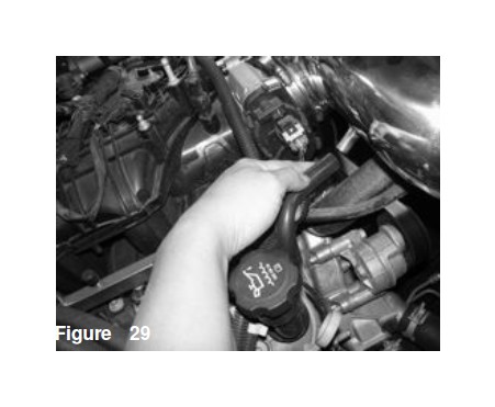
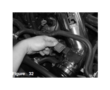
Disconnect the crank case ventilation line from the air duct resonator section located on top of the intake manifold.
Now remove the crank case ventilation line from the valve cover. You will need to unclip a plastic lock in order for you to remove this line from the valve cover.
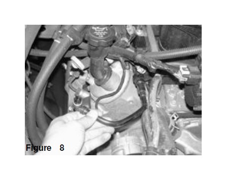
This factory CCV line will no longer be used is this installation.
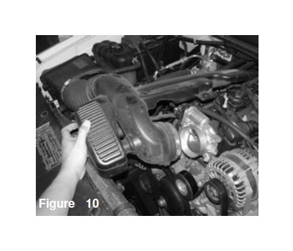
You may now remove the entire air duct
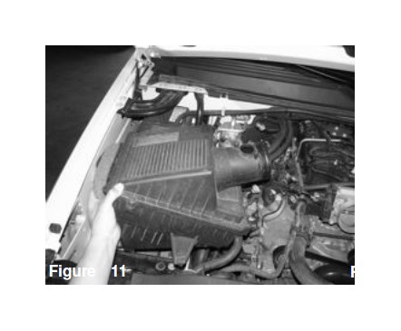
Remove the entire air box assembly
Place the 4.0” velocity stack onto the side opposite from the two tabs on the heatshield
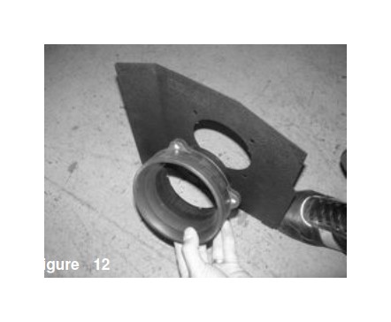
Place four M6x12 allen bolts onto the velocity stack attaching the velocity stack onto the heatshield.
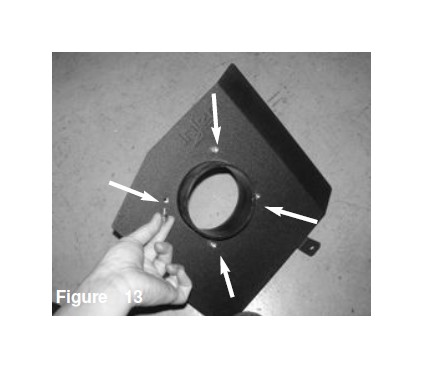
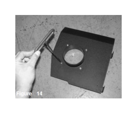
Use a 5mm allen driver and secure the velocity stack to the heatshield.
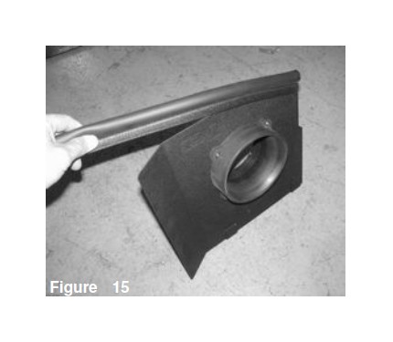
Place the rubber trim onto the top of the heatshield
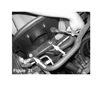
Locate and remove the two 10mm bolts located on top of the factory air box assembly tray.
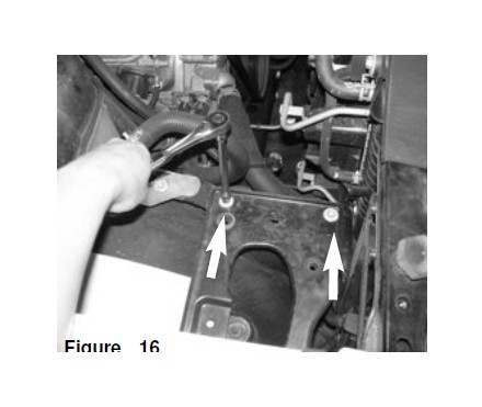
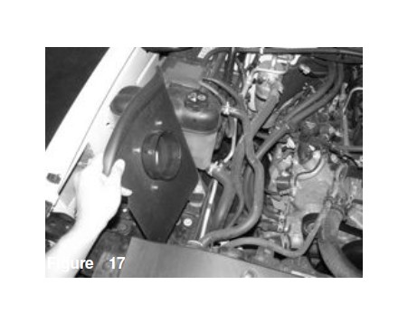
Place the heatshield onto the air box assembly tray.
Align the two tabs on the heatshield with the two bolts removed from figure 16.
Re-use the two 10mm bolts removed from figure 16 and mount the shield to the air box assembly tray. Leave these bolts loose for now.
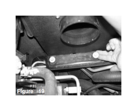
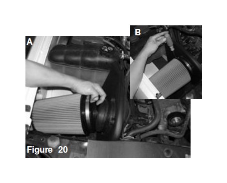
Figure A: With the heatshield loose, place the filter onto the velocity stack Figure B: Nowtighten the clamp on the filter securing it to the velocity stack
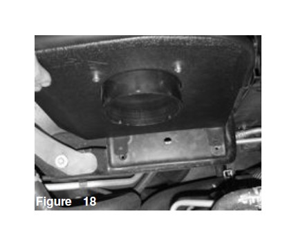
Use a 10mm socket/rachet and tighten the two 10mm bolts to secure the heatshield to the air box tray.
Place the 4.0” hump hose and two #64 clamps onto the 4.0” end of the velocity stack.
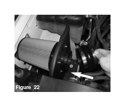
Use a 8mm nut drive to tighten the clamp on the hump hose to secure it to the 4.0” side of the velocity stack
Place the 10”-10mm vacuum line onto the breather port on the valve cover.
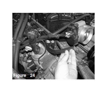
Place the supplied Chevy sleeve hosew/ clamp over the slotted tube on the cast intake pipe.
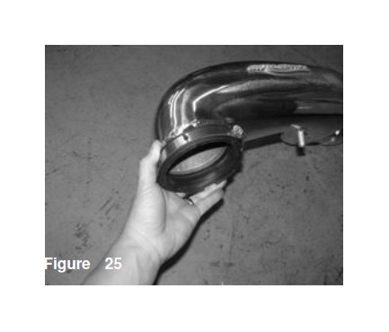
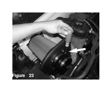
Place the MAF sensor end into the 4.0” hump hose.
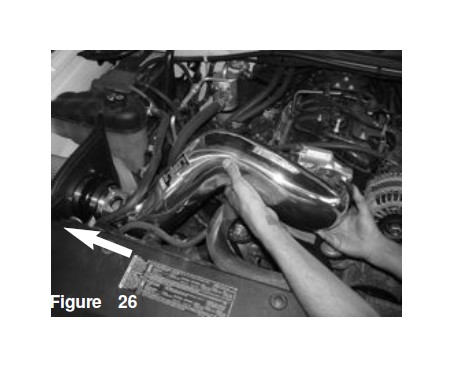
Now firmly push the sleeve hose end of the intake pipe onto the throttlebody
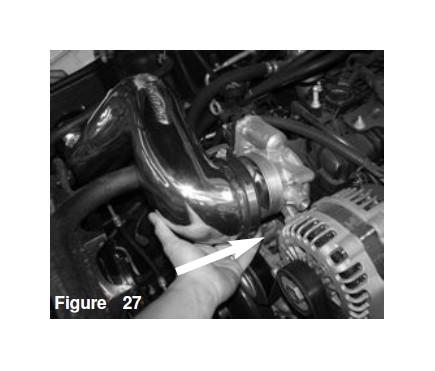
Figure A: Use a 8mm nut driver and firmly tighten the clamp on the throttlebody Figure B: Now tighten the clamp on the 4.0” hump hose MAF sensor end.
Connect the 10mm vacuum line to the welded nipple on the cast intake tube
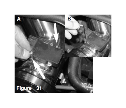
Place the MAF sensor onto the welded machined adapter on the cast intake tube
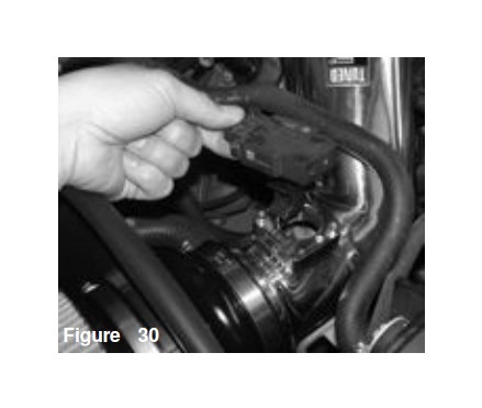
Figure A: Place two M4x10 screws onto the MAF sensor Figure B: Use a 2.5mm allen to secure the MAF sensor to the welded machined adapter
Re-connect the MAF sensor harness to the MAF sensor.
Re-install the engine cover
Your installatiion is now complete. Start your engine and allow the on board computer to adjust to the added volume or air. Listen to the engine and make sure there are no rattles or spikes when idling. Enjoy the added power and performance of the best intake system today