FREE 1 to 3-Day Delivery on Orders $149+ Details
How to Install SLP 2300 TVS 520 HP Supercharger on your Sierra
STOCK DISASSEMBLY
The following section will guide you through the disassembly of the stock components. Special care should be taken to label fasteners and parts that are taken off during this procedure since many will be reused:
1. Cover both fenders with fender covers to protect the vehicle finish.
2. Disconnect the (-) negative & ( ) positive connections to the battery.
3. Lift up on the front of the engine cover and pull it towards you to remove it from the engine bay.
4. Loosen the worm drive clamp that holds the clean air tube to the MAF (mass airflow) sensor and the clamp that holds the clean air tube to the throttle body. Remove the PCV (positive crankcase ventilation) line from the front of the passenger side valve cover. Remove clean air tube from vehicle.
5. Use a 15mm socket to rotate the tensioner clockwise and remove the belt from engine.
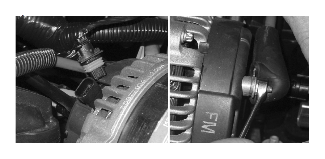
6. Disconnect the alternator harness and the B cable from the alternator. Remove the alternator from the engine.
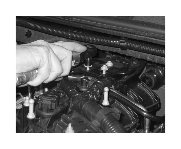
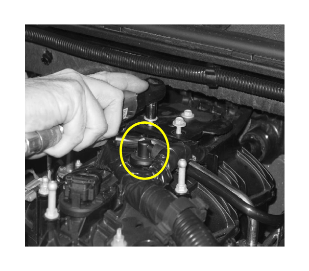
7. Disconnect the MAP (manifold absolute pressure) sensor, ETC (electronic throttle control), VMV (vapor management valve also known as EVAP solenoid) and the fuel injectors.
8. Use a 10mm socket to remove the 3 bolts and 1 nut fastening the harness retention pieces to the intake manifold.
9. Remove the PCV line from the top of the intake manifold and the rear of the driver side valve cover.
10. Disconnect the fuel line from the driver side fuel rail and both VMV lines from the VMV.
11. Disconnect the brake booster hose at the fitting on the brake booster.
12. Loosen and remove the (10) M6 bolts that fasten the intake to the cylinder heads using an 8mm socket.
13. Remove the intake manifold and clean the intake mounting surfaces. Put tape over the intake ports to prevent debris from entering the engine. CHECK THE TYPE OF VALLEY COVER PLATE YOU HAVE AT THIS TIME AS DESCRIBED ON PAGE 4 ABOVE
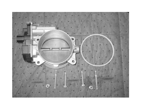
14. Remove the throttle body, the 2 (two) throttle body-mounting studs and throttle body gasket from the stock intake manifold (a new gasket is supplied, so you may discard the old one)
15. Remove the fuel rail and set aside for use later.
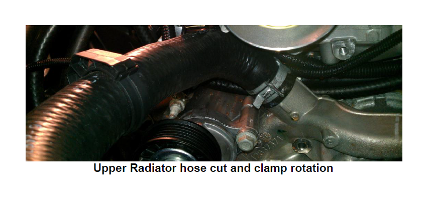
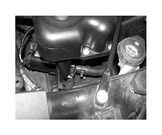
16. Drain the coolant. Remove the upper radiator hose on the waterpump and cut 1.5” off of the end. Rotate the clamp so it will not interfere with the FEAD bracket installed later. Refill the coolant.
The following section will guide you through the required modifications of existing components and build up of the assemblies used to complete the installation.
VMV Modification
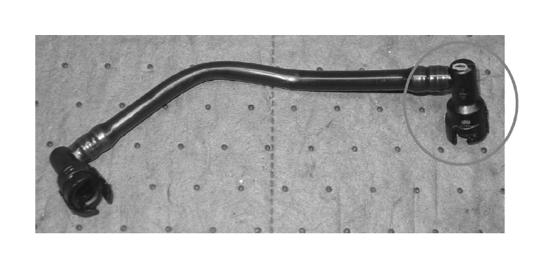
1. Using a knife, carefully cut tubing to remove a 90 degree SAE fitting from the stock VMV line.
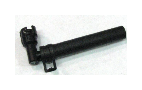
2. Use (1) 3/8” constant tension clamp to secure the supplied VMV line to the 90 deg fitting (5.3L hose length is pictured, supplied hose for a 6.2L truck is much longer).
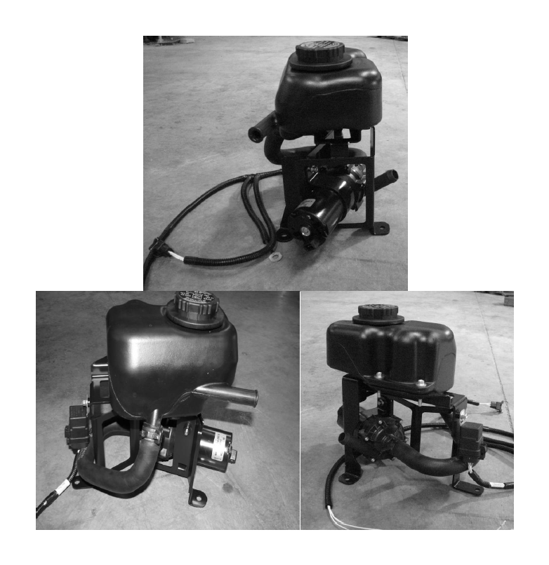
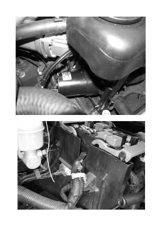
Intercooler Reservoir & Pump Bracket (Use photos below to aid in steps below)
1. Using the I/C Pump Bracket and (1) M6 x 1.0 x 18.5 bolt, mount the pump to the Degas Bottle Bracket. Torque to 8 – 12 Nm.
2. Mount the relay of the I/C Wiring Harness to the bracket using (1) M6 x 1.0 x 18.5mm bolt. Torque to 8 – 12 Nm.
3. Mount the Reservoir to the bracket using (2) M6 bolts and (1) M6 cap screw with an M6 washer. Torque to 8 – 12 Nm.
4. Use the formed hose to connect the outlet of the reservoir with the inlet of the pump. Use (2) constant tension clamps to secure it in place.
5. Connect the I/C Pump plug on the wiring harness to the I/C Pump.
Intercooler Reservoir Assembly Mounting
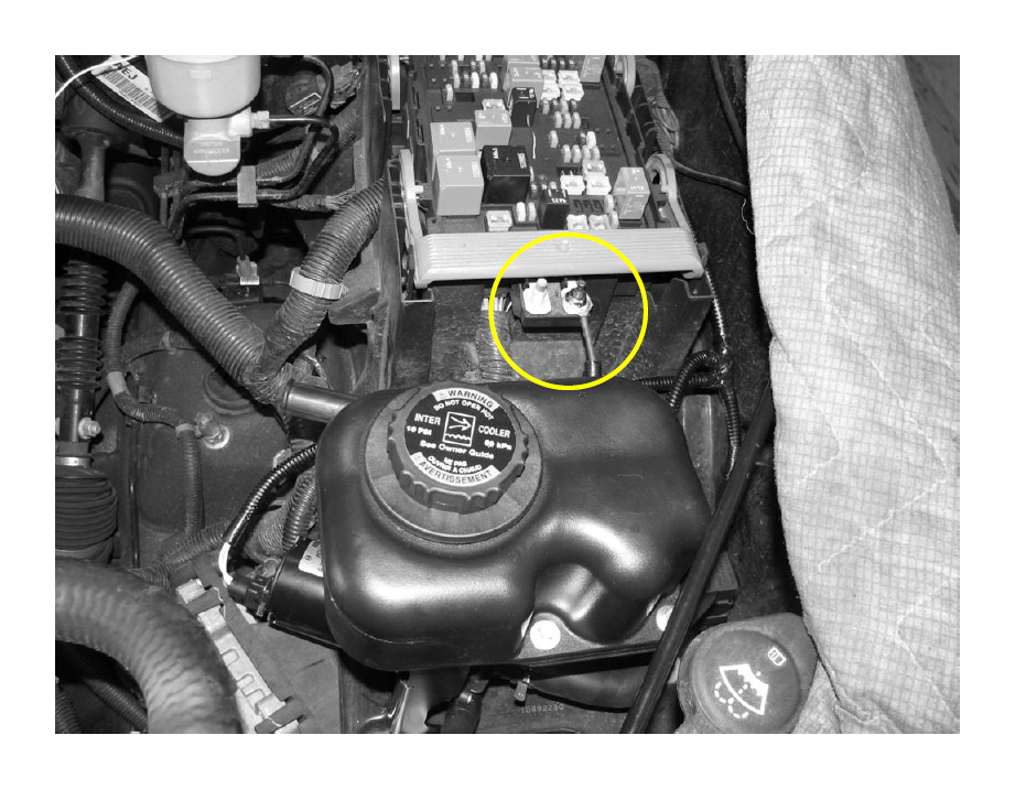
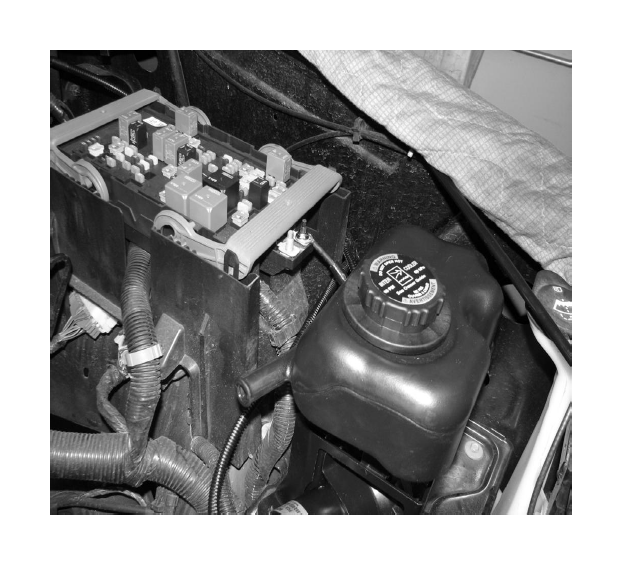
1. Install the reservoir assembly in the spare battery tray by reusing the hardware that holds the tray in place. Make sure not to pinch or crush any of the wiring. Torque the fasteners to 8 – 12 Nm.
a. Connect the short lead from the wiring harness to the spare M6 post on the fuse block. Use (1) M6 nut from the stock intake assembly and torque to 8 – 12 Nm.
b. Run the remaining lead in between the fuse box and the fender to the rear of the truck. Connect the eyelet to the grounding post.
3. Solder the supplied 10 amp fuse link to single lead (with no eyelet) to an ignition-on signal wire in the fuse box.
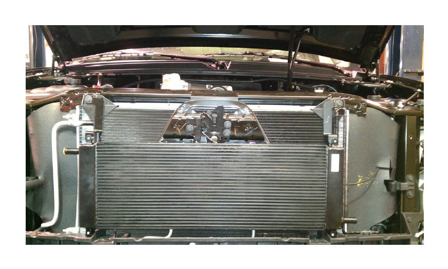
Intercooler Radiator Assembly Mounting
1. Remove the radiator trim cover by removing the pushpin retainers by pulling the center pin then lifting the cover up.
2. Remove the (4) M6 bolts holding the grille to the front structure. Using pliers, squeeze the retaining clips from the inside to remove the grill from the vehicle.
4. Remove the top (2) bolts securing the condenser in place and bolt holding the bottom of the power steering fluid cooler in place.
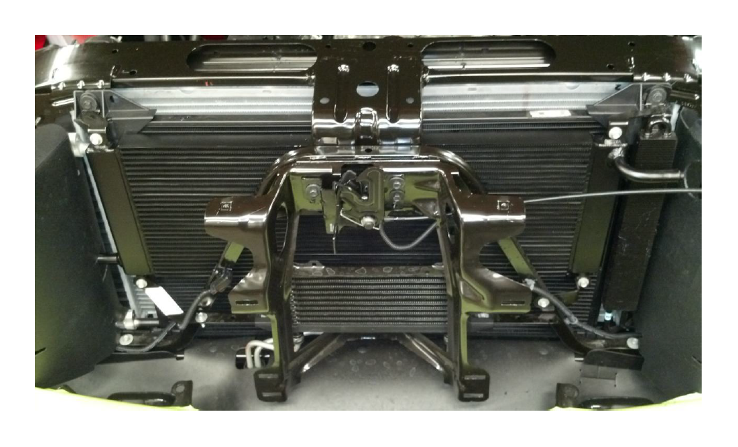
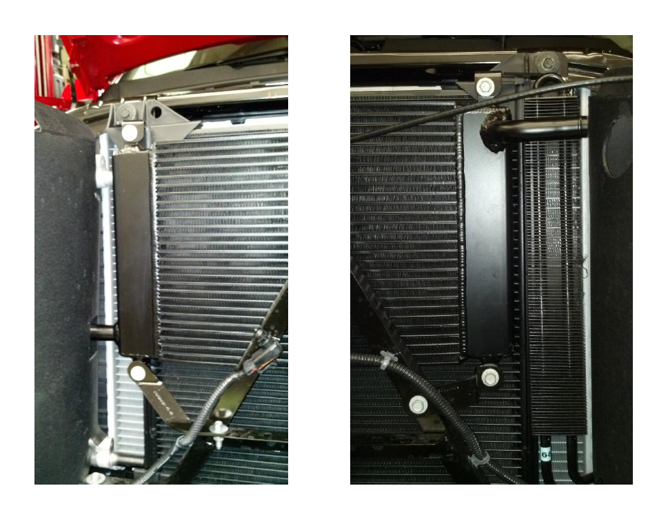
5. Pull the power steering fluid cooler forward. Slide the low temp radiator, from the driver side to the passenger side, in between the front structure and the condenser on PICKUP MODELS ONLY. FOR SUV MODELS the Radiator is to MOUNT IN FRONT OF THE CONDENSER STRUCTURE. The orientation of the intercooler changes between models as well. See photos below. There are two separate sets of mounting tabs included in this kit. Be sure to use the kit specified for your vehicle. SUV or Pickup. See photos for bracket orientation and radiator mounting on the next page.
SUV MODELS
PICKUP MODELS
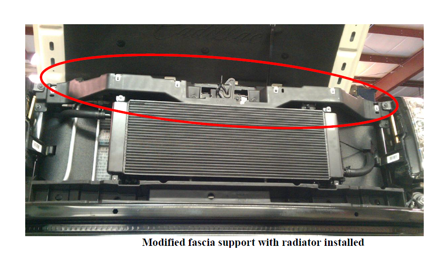
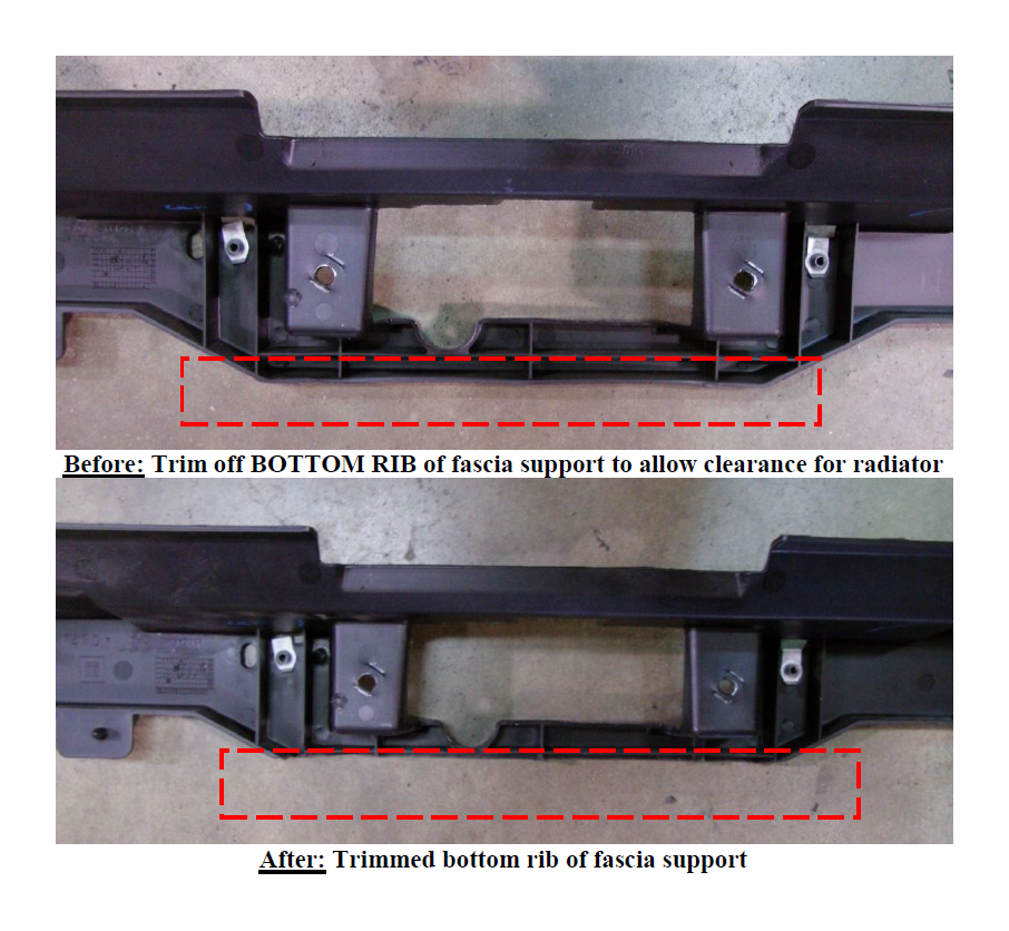
For 6.2L Escalade/Denali models, the fascia support will have to be removed and modified to allow the radiator to fit properly. Photos below show the modified portion of this support.
5. Mount the top of the Radiator using the brackets provided. Use (2) M6 x 1.0 x 18.5 bolts to fasten the brackets to the upper Radiator mounting tabs. Use the take off fasteners to secure the brackets to the front structure. Leave these fasteners loose.
6. Mount the bottom of the Radiator using the brackets provided. Use (2) M6 x 1.0 x 18.5 bolts to fasten the brackets to the lower Radiator mounting tabs. Use (1) M6 x 1.0 x 18.5 bolt and (1) M6 Nut to secure the lower passenger side bracket to the front structure. Use the take off fastener to secure the lower driver side bracket to the front structure.
7. Torque all bolts to 7 ft-lbs.
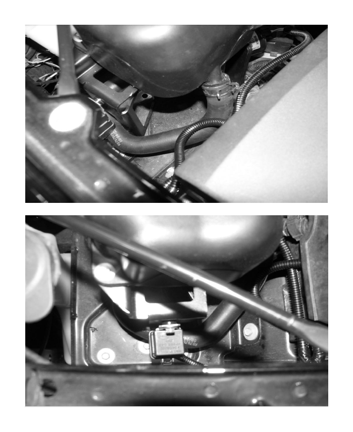
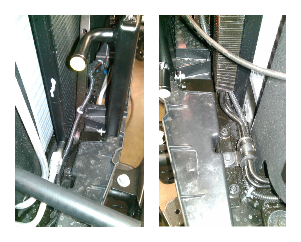
8. Connect the Radiator Inlet (driver side) to the I/C Pump using the ¾” bulk hose that is 19” long. Route the hose from the Radiator through the front structure to the pump. Secure the hose to the fittings using (2) constant tension clamps. Trim plastic as needed to route hoses through engine bay.
9. Connect the 52” bulk hose to the Radiator Outlet (Passenger Side) using (1) constant tension clamp and route the hose through the front structure and along the stock heater lines.
10. Inspect all installed coolant lines for any kinks.
Intake Manifold and SLP Rotor Pack
1. Remove Fuel Charging Assembly with Intercooler from packaging.
2. Install the supplied intake to cylinder head gaskets to the lower intake manifold.
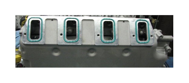
3. Remove the tape from the cylinder heads. Carefully clean the cylinder head to intake manifold mating surfaces using Brake Clean or rubbing alcohol.
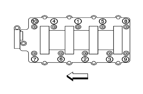
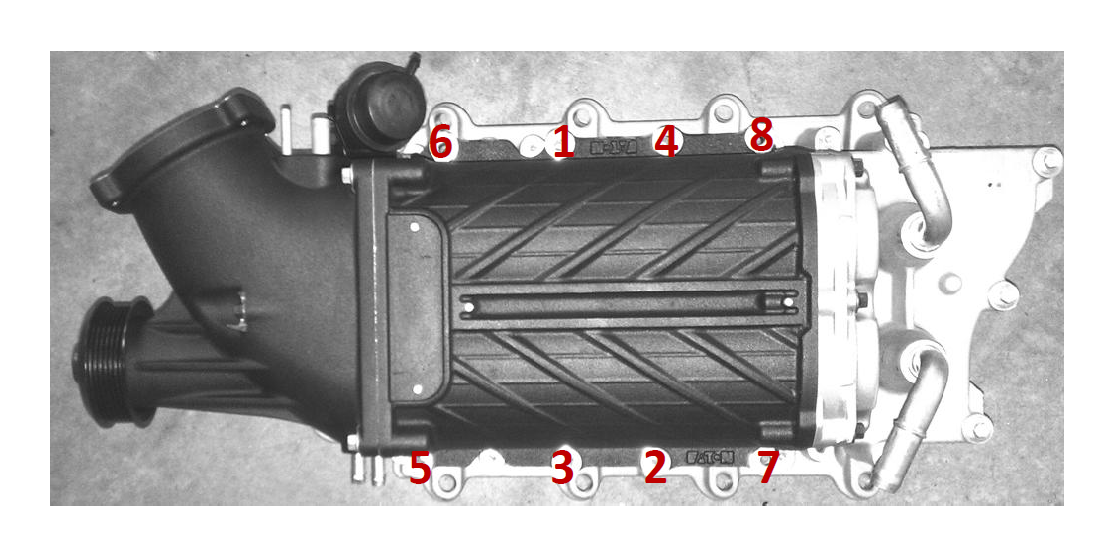
4. Carefully place the lower intake manifold assembly (with gaskets) down onto the cylinder heads. Be careful not to damage your sealing surfaces or gaskets during this step. Fasten the intake using (10) M6 x 1.0 x 74.5mm bolts. Torque to 8 f-lbs in the sequence shown.
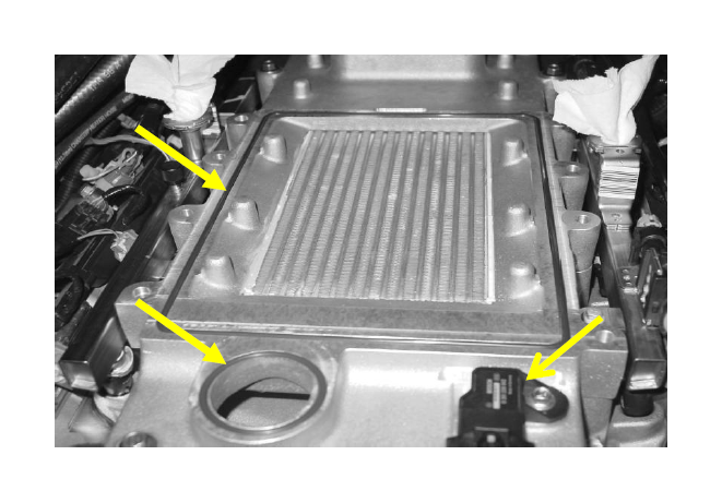
5. Install the lower manifold to supercharger case gasket and the supercharger bypass gasket in the intake manifold assembly. See arrows below.
6. Install the TMAP sensor using the flanged bolt provided in the same bag as the injectors are in.
7. Connect the P-Side hose coming from the new radiator routed along the stock heater lines to the passenger side rear intercooler fitting using (1) constant tension clamp. Connect the D-Side hose coming from the reservoir bottle inlet routed along the main wiring harness to the driver side rear intercooler fitting using (1) constant tension clamp.
8. Route the B cable in between the water pump and the lower intake manifold and in between the alternator bracket and the lower intake manifold.
9. Remove the M8 bolt shown from the water pump.
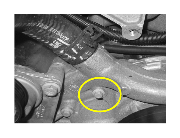
10. Install the Front Belt Drive Bracket using (3) M8 x 1.25 x 123mm bolts. Torque to 18 ft-lbs. Fasten the idler to the bracket using (1) M8 x 1.25 x 28mm bolt. Torque to 18 ft-lbs Nm.
11. Remove the SLP Rotor Pack from the packaging. Install the “TVS 2300” and “SLP Supercharged” Badges with the supplied Allen head M4 black bolts. Next, install the SLP Rotor Pack below to the lower manifold installed on step 4 above using (8) M8 x 1.25 x 84mm bolts. Torque to 18 ft-lbs in the sequence shown.
12. Route the TMAP harness between the coils and injectors on the driver side and connect TMAP. Route the portion that connects to the MAF towards the passenger side airbox area for connection later.
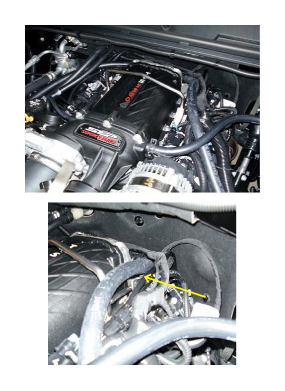
13. Install the STOCK fuel rail and provided injectors using the provided spacers. Torque the fuel rail bolts to 8 ft-lbs. Connect the fuel line to the rail and the vehicle harness to all eight (8) injectors. It may be necessary to bend the back of the fuel rail inlet down slightly to clear the intercooler hose. See arrow in second photo below.
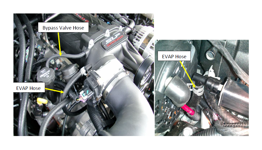
14. Run the PCV Purge tube from the lower port on the driver side of the supercharger to the rear of the driver side valve cover using (2) 3/8” constant tension clamps. Connect the supercharger bypass valve port to the port (smaller of the two ports) on the passenger side of the supercharger. Using the modified EVAP line, connect the 90deg fitting to the front of the EVAP Solenoid and connect the bulk hose to the upper port on the passenger side of the supercharger using (1) 3/8” constant tension clamp. Run the hose from the EVAP line along the B cable from the alternator as shown in photos below.
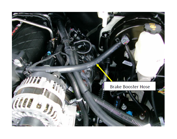
15. Trim the supplied brake booster hose to 17”. Connect the Brake Booster Hose to the fitting on the brake booster using the stock take off constant tension clamp. Route the hose around the back of the supercharger and secure it to the 5/8” fitting on the passenger side of the supercharger using (1) constant tension clamp
16. Install the (2) take off throttle body studs in the (2) upper holes in the front inlet of the supercharger. Torque to 8 ft-lbs. Install the new throttle body gasket in the front inlet of the supercharger.
17. Using the rest of the take off hardware, fasten the throttle body to the supercharger. Torque to 8 ft-lbs. Connect the wiring harness to the ETC connector.
18. Install the FEAD belt.
AIR BOX INSTALLATION
1. Remove the entire stock airbox as one piece. It is only held in by 3 rubber pins. Pull up and out with some force to remove the stock box from the truck.
2. Unscrew the factory MAF sensor and remove it from the airbox (screw size is a standard T15 Torx). Set it aside in a safe place and be VERY CAREFUL removing as it is very delicate.
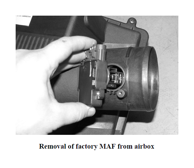
3. Next remove the four bolts in the black plate that was under the stock airbox, as well as the black plate.
4. Next, insert the factory MAF sensor into the airbox MAF tube included and thread in the factory screws.
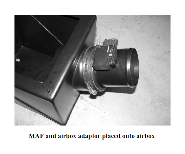
5. Insert one of the two rubber inlet tube adaptors onto the airbox, and then proceed to insert the wider end of the airbox adaptor into the airbox. Make sure the airbox adaptor sits concentrically in the hole and the MAF is facing up as in the below picture. Proceed to tighten the worm drive clamp.
6. Next place SLP’s new cold air box in place with the large square opening in the box facing the fender.
7. Only three of the bolts will be reused to hold the SLP airbox in place. Tighten all three bolts to secure the box.
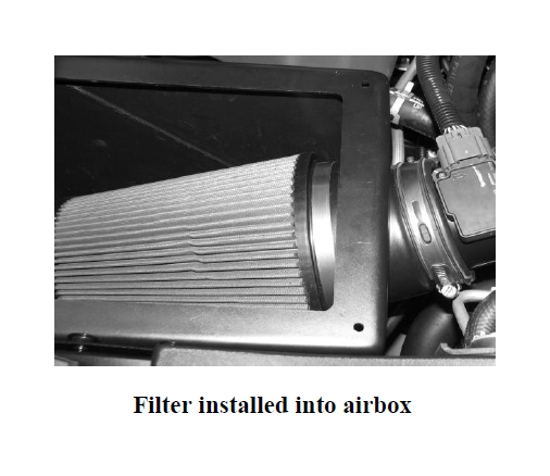
8. Next install the SLP high flow filter. The filter is a tight fit when installing it into the box, so the following steps must be taken to get the filter in the box with ease. First, position the filter so that the entire open end of the filter is under the mounting stub on the inside of the box. Push the filter down and in, under the stub. The filter will now be completely in the box under the mounting stub. Next, slide the filter to the fender side of the box so that the outlet of the filter can slide onto the mounting stub inside the box. Slide the filter all the way onto the stub and tighten the worm drive clamp.
9. Place the SLP cover onto the air filter housing and push the screw plugs into the housing. Insert and tighten the four plastic screws into the screw plugs to secure the lid to the air filter housing.
10. Next reconnect the MAF wire harness to the MAF.
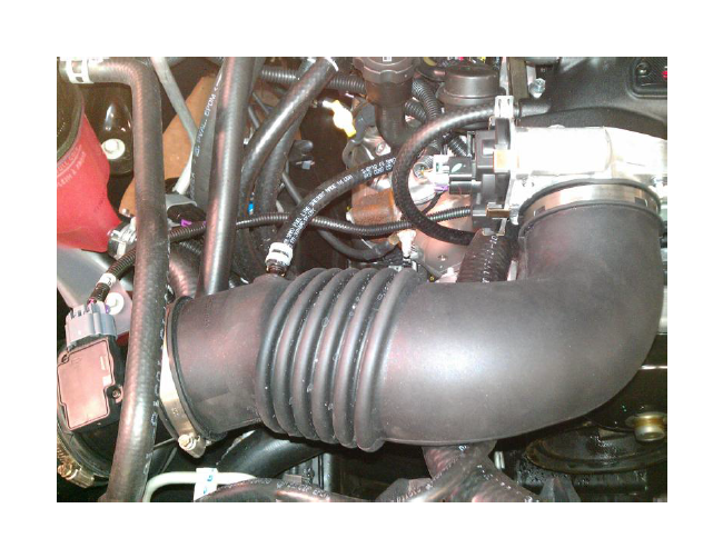
11. Install the provided induction tube, tighten all clamps, and install the supplied PCV hose with clamps onto both the tube and the nipple on the PS valve cover.
12. FOLLOW INSTRUCTIONS included in the “INTUNE” Handheld Programmer before starting vehicle as engine damage will result and you WILL VOID your warranty.