 FREE 1 to 3-Day Delivery on Orders $149+ Details
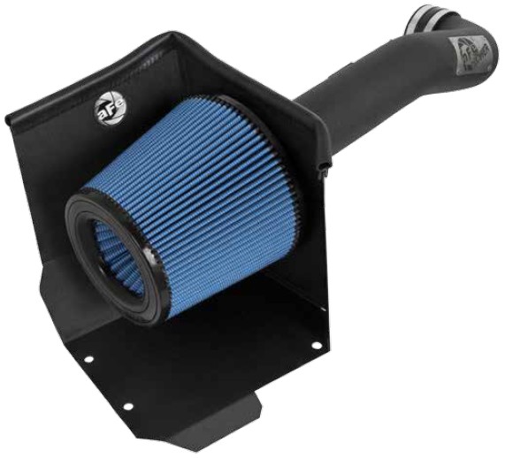
How to Install aFe Magnum Force Stage 2 Pro Dry S Cold Air Intake - Matte Gray on your Sierra

Shop Parts in this Guide
- AFE Magnum FORCE Stage-2 Cold Air Intake with Pro DRY S Filter; Matte Gray (14-18 5.3L Sierra 1500 w/ Electric Cooling Fan)
- AFE Magnum FORCE Stage-2 Cold Air Intake with Pro DRY S Filter; Matte Gray (14-18 6.2L Sierra 1500 w/ Electric Cooling Fan)
- AFE Magnum FORCE Stage-2 Cold Air Intake with Pro 5R Oiled Filter; Matte Gray (14-18 5.3L Sierra 1500 w/ Electric Cooling Fan)
- AFE Magnum FORCE Stage-2 Cold Air Intake with Pro 5R Oiled Filter; Matte Gray (14-18 6.2L Sierra 1500 w/ Electric Cooling Fan)
• Please read the entire instruction manual before proceeding.
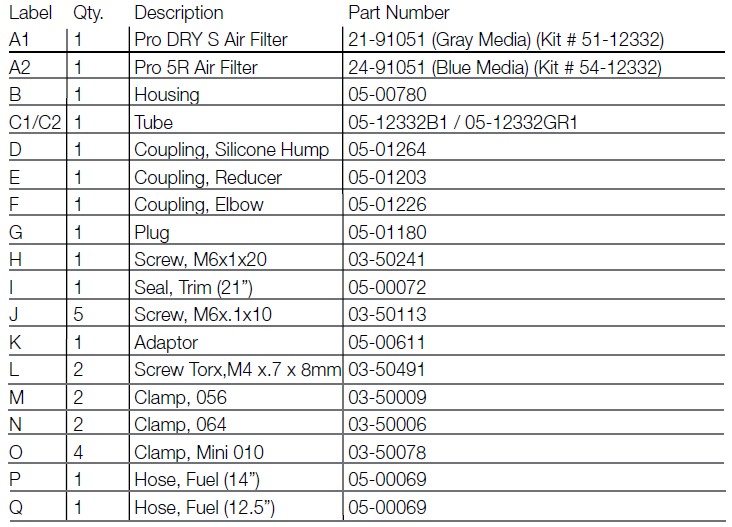
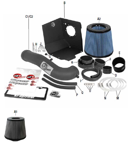
• Ensure all components listed are present.
• If you are missing any of the components, call customer support at 951-493-7100.
• Ensure you have all necessary tools before proceeding.
• Do not attempt to work on your vehicle when the engine is hot.
• Disconnect the negative battery terminal before proceeding.
• Retain factory parts for future use.
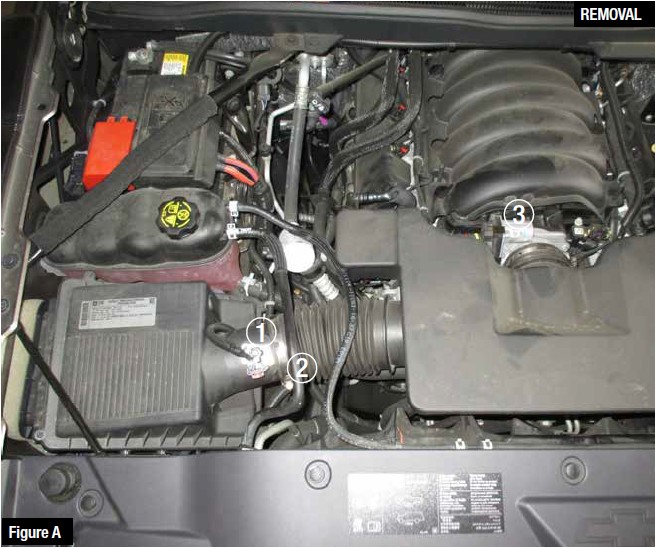
Refer to Figure A for Steps 1-3
Step 1: Disconnect the MAF sensor plug 1 from stock intake tube.
Step 2: Loosen clamp from OE air box housing and OE Intake tube 2 .
Step 3: Loosen clamp from throttle body 3 .
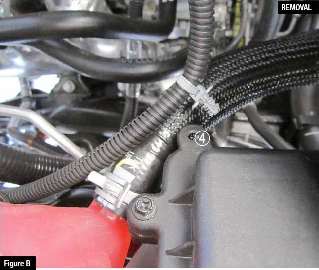
Refer to Figure B for Steps 4-5
Step 4: Disconnect the MAF sensor harness clip 4 from the OE air box.
Step 5: Remove OE air box from vehicle.
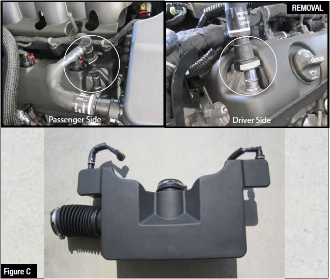
Refer to Figure C for Steps 6-7
Step 6: Disconnect the OE crank case breathers from the valve covers (as shown) on both sides of the engine.
Step 7: Carefully remove the entire intake tube plenum with the crank case breather plugs attached.
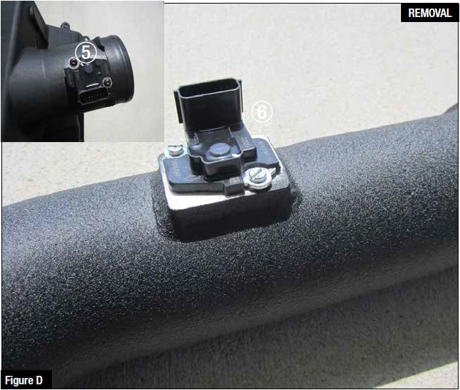
Refer to Figure D for Steps 8-9
Step 8: Remove MAF sensor 5 from the factory housing.
Step 9: Install MAF sesnor 6 from the factory housing into the aFe intake tube using the
provided screws.
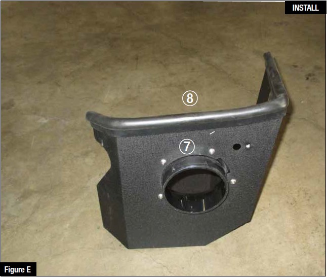
Refer to Figure E for Steps 10-11
Step 10: Install filter adaptor 7 using supplied screws onto aFe intake housing.
Step 11: Install seal trim 8 onto upper edge of aFe housing.
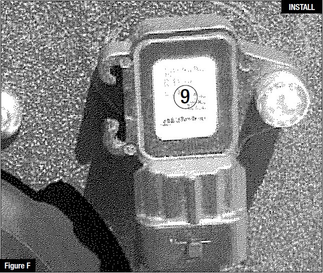
Refer to Figure F for Step 12
Step 12: 2011 and newer 6.2L trucks have an extra sensor 9 on the air box. Transfer this sensor to the new aFe housing. With all other trucks without sensor, plug the unused hole with supplied plastic push plug.
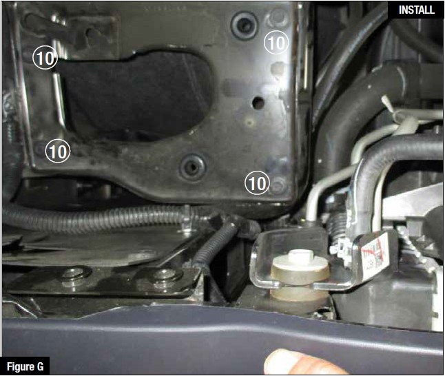
Refer to Figure G for Steps 13-14
Step 13: Remove the 4 bolts 10 from the stock air box bracket and save them for later use.
Step 14: Remove air box bracket from vehicle.
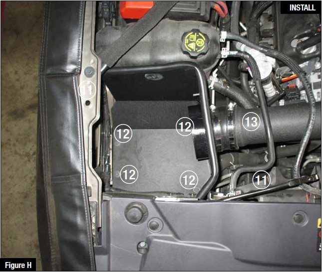
Refer to Figure H for Steps 15-18
Step 15: Remove top bolt from reinforcement bar 11 and loosen bottom bolt. Swivel
reinforcement bar out of the way as pictured.
Step 16: Using the 4 bolts 12 from step 13, install the aFe intake housing.
Step 17: Install the elbow coupling 13 onto the filter adaptor.
Step 18: Install aFe intake tube onto the elbow coupling
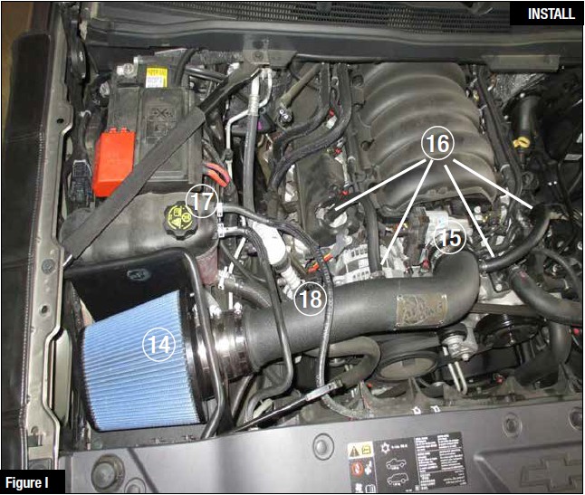
Refer to Figure I for Steps 19-26
Step 19: Install air filter using supplied screw clamp 14 .
Step 20: Install the coupler 15 onto the throttle body with the provided clamps.
Use the hump coupling for V8-5.3L or the reducer coupling for the V8-6.2L
Step 21: Install intake tube onto the throttle body coupler.
Step 22: Adjust elbow coupler and intake tube and tighten clamps.
Step 23: Install supplied crank case breather hoses 16 onto engine and intake tube
using supplied clamps and tighten (longer breather hose installs on driver side.)
Step 24: Using pliers reposition coolant hose pinch clamps 17 and hoses on coolant reservoir clockwise to clear intake tube if necessary.
Step 25: Reconnect MAF sensor harness 18 .
Step 26: Make sure all clamps and connections are secure. Your installation is now complete.
Thank you for choosing aFe Power!


