 FREE 1 to 3-Day Delivery on Orders $149+ Details
How to Install Fabtech 4 in. MagneRide Uniball Upper Control Arm System on your Sierra

Shop Parts in this Guide
INSTRUCTIONS
FRONT SUSPENSION
1. Disconnect the negative terminal on the battery. Jack up the front end of the truck and support the frame rails with jack stands. NEVER WORK UNDER AN UNSUPPORTED VEHICLE! Remove the front tires.
2. Starting on the driver side of the truck, remove the bolt attaching the brake line tab to the spindle.
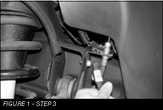
3. Follow the wheel speed sensor wire from frame rail plug. Separate the wire from the upper control arm. Disconnect the adjusting rod from the upper control arm bracket. SEE FIGURE 1
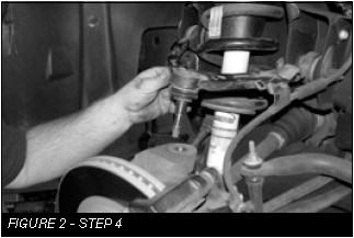
4. Remove the nuts securing the tie rod and upper arm ball joints to the spindle. Separate both joints from the spindle and remove the upper control arm and tie rod from the spindle. SEE FIGURE 2
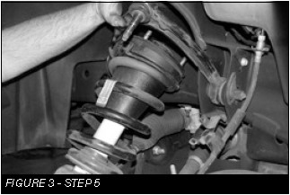
5. Remove the factory coil over and save. SEE FIGURE 3
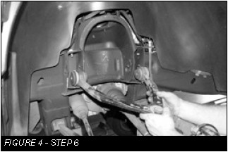
6. Remove the upper control arm form the vehicle and save the factory hardware. Remove auto ride bracket and save for reinstallation. SEE FIGURE 4
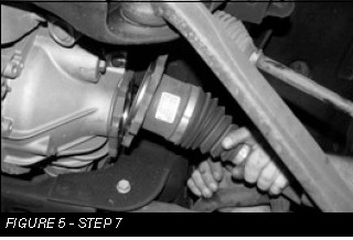
7. Remove the factory CV shaft from the differential drive flange on both sides of vehicle. SEE FIGURE 5
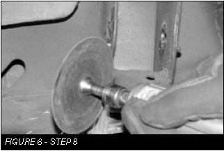
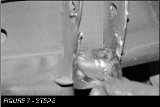
8. Using a die grinder remove the factory droop stop off the control arm pocket. SEE FIGURES 6-7
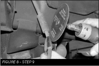
9. Using a die grinder, partially cut the brake line bracket. This will allow the bracket to be bent and removed from the brake line. Be careful not to damage brake hose. SEE FIGURE 8
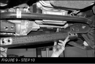
10. Remove the factory rear cross member and retain factory hardware. SEE FIGURE 9
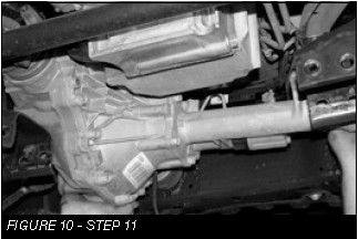
11. Disconnect the drive shaft from the front differential solenoid wiring. Disconnect the differential vent tube and remove the diff. SEE FIGURE 10
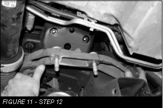
12. Locate the factory passenger side diff mount and remove. SEE FIGURE 11
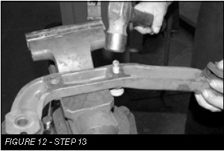
13. Remove the factory studs from the differential mount and reinstall the differential mount. SEE FIGURE 12
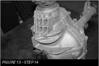
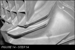
14. Locate the factory diff and cut off the driver side rear cooling fins. SEE FIGURES 13-14
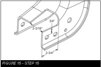
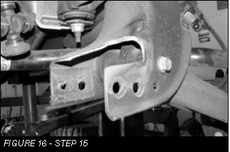
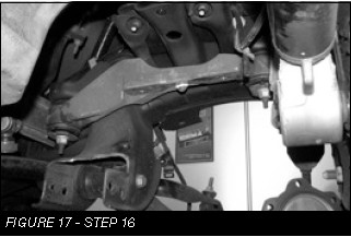
15. Locate the factory rear driver lower control arm pocket / cross member mount. Using a die grinder remove the material shown in the diagram below. SEE FIGURES 15-16
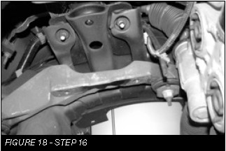
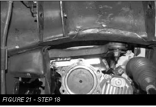
16. Locate the factory driver side Diff mount. Using a die grinder remove the locating pin from the mount. SEE FIGURES 17-18
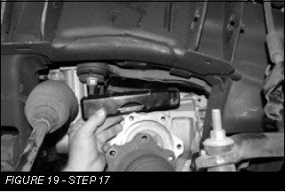
17. Locate the FT20625 driver side diff mount and the FT20626 passenger side diff mount. Staring on the driver side, remount the diff with two M12-1.75 x 70mm bolts. SEE FIGURE 19
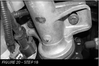
18. Using the passenger side differential mount, two ½”-13 x 4” bolts, nuts and washers, mount the passenger side of the differential. NOTE: Install bolts from the bottom so the threads are at the top. Torque the 1/2” bolts to 90 ftlbs and the 12mm bolts to 65 ft-lbs. SEE FIGURE 20-21
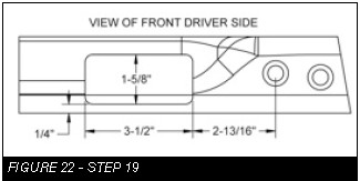
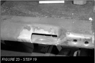
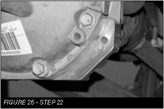
19. Locate the factory rear cross member. Using a die grinder remove the material from the driver side shown in the diagram. SEE FIGURES 22-23
20. Reinstall Factory rear crossmember. Torque bolts to 100 ft-lbs.
21. Reconnect the drive shaft, differential vent tube and solenoid with factory hardware. Torque to 17 ft-lbs.
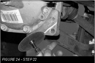
22. Trim the front of the differential to clear the new skid plate. SEE FIGURES 24-25
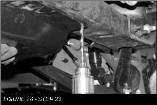
23. Locate the FT20627BK skid plate and the two 3/8”- 16x3/4” self taping bolts. Mount the skid plate to the factory front cross member using two of the factory front bolts. With front of the skid plate mounted, use the back two holes in the skid plate for a drill guide. Drill two 5/16” pilot holes and install the two 3/8” self taping bolts. Torque to 21 ft-lbs. Be careful not to over torque. SEE FIGURE 26
24. Locate the FT20558BK driver upper control arm and one FT20619 ball joint, two FTS1001bushings, two FT1002 bushings, two grease zerks FT84, and two FT1500-6-101 sleeves.
25. Install one FTS1001 bushing, one FT1002 bushing and a FT1500-6-101 sleeve zerk in each barrel. Use the FTLUBE urethane lube on each bushing.
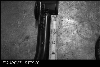
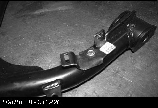
26. Measure 3” like shown in FIGURE 27 and drill a hole using a 11/64” bit. Install the factory auto ride bracket to the new control arm using the supplied #12 Tek Screw. SEE FIGURE 28
27. Repeat steps 23-25 using FT20559BK for passenger side.
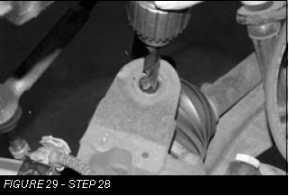
28. Using a 1/2” drill, chase out the end of the upper ball joint tapper on the spindle. SEE FIGURE 29
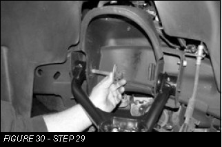
29. Install the upper control arm in to the frame using factory hardware and leave loose at this time. SEE FIGURE 30
30. If installing Dirt Logic coilover, P/N FTS810151, do so at this time using hardware provided with that shock. Otherwise, continue with Step 31 with the factory shock.
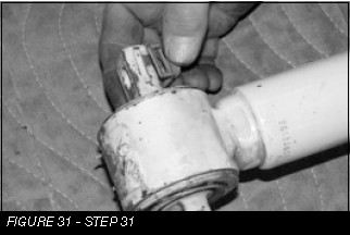
31. Locate the factory coil over and remove the sheet metal nut from the lower bar pin. SEE FIGURE 31
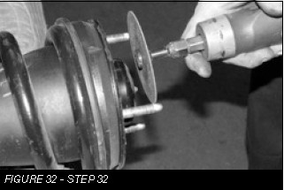
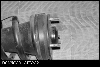
32. Trim a 1/4” off the studs on the top side of the coil over. SEE FIGURE 32-33
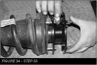
33. Install the FT20560BK coil spacer using the factory nuts and torque to 30 ft-lbs. SEE FIGURE 34
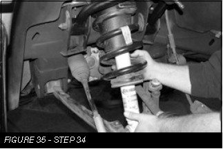
34. Locate the three 7/16” nylock nuts and install the coil over into the upper shock mount. Leave loose at this time. SEE FIGURE 35
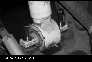
35. Locate the two 7/16”-14 x 2-1/4” bolts, nuts and washers and install the lower bar pin mount onto the lower control arm. Torque the upper and lower bolts to 59 ft-lbs. SEE FIGURE 36
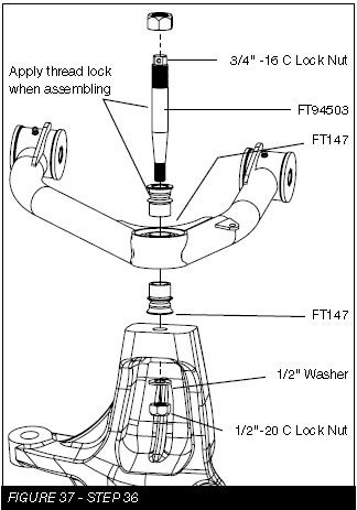
36. Locate FT94503 (Uniball adapter pin) and two FT147 (Uniball misalignment spacers).
SEE FIGURE 37 FOR STEPS 37-41
37. Insert the uniball pin into the factory knuckle upper ball joint taper. Install the 1/2-20 lock nut with thread lock compound and flat washer onto the bottom side of the pin. This will lock the pin into the knuckle. Torque to 150 ft-lbs.
38. Install one FT147 uniball misalignment spacer on to the pin.
39. Swing the control arm down, slide the pin into the uniball on the control arm seating the lower FT147 spacer in the control arm.
40. Install the upper FT147 (uniball misalignment spacer) onto the pin.
41. Install the 3/4”-16 lock nut on the top side of the pin with thread lock compound and torque to 150 ft-lbs.
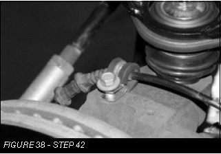
42. Install the FT clamp on top of the spindle to hold the wheel speed sensor wire. SEE FIGURE 38
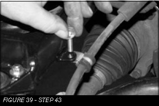
43. Use an FTCLAMP, 1/4”-20 x 1” bolt, nut, and washer to connect the brake line to the control arm. SEE FIGURE 39
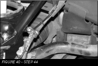
44. Reconnect the wheel speed sensor and zip tie to the brake line. Reconnect the auto ride adjusting rod to the control arm. SEE FIGURE 40
45. Repeat steps 3-41 on passenger side of vehicle where applicable.
REAR SUSPENSION
(FOR SUV REAR SUSPENSION SKIP TO STEP 51)
46. Locate the FTBK15 blocks and the four FT1500U u-bolts. Disconnect the rear shock at the lower mount. With the factory block and u-bolts removed and the rear axle clear of the leaf spring, make sure the block will fully seat onto the leaf spring and the spring pad of the rear axle housing with the wide end of the block to the rear of the vehicle. On the leaf spring make sure the center pin head will seat fully into the hole of the block allowing the top surface of the block to rest against the leaf spring. Install the new u-bolts with washers and nuts from the FT916H hardware kit and torque to 150 ft-lbs. Note – The Vehicle’s stance will be level with the Fabtech block. To maintain the factory stance (rear high) retain the factory block when installing the Fabtech block. NOTE: For FTS21155 install FTBK3 (3” Block).
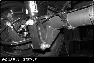
47. Install FT20673BK rear shock bracket like shown in FIGURE 41. Torque to 100 ft-lbs
48. Install tires and wheels and torque lug nuts to wheel manufacturer’s specifications. Turn front tires left to right and check for appropriate tire clearance. Note - Some oversized tires may require trimming of the front bumper & valance.
49. Check front end alignment and set to factory specifications. Readjust headlights.
50. Recheck all bolts for proper torque.
51. Recheck brake hoses, ABS wires and suspension parts for proper tire clearance while turning tires fully left to right.
52. Check the fluid in the front and rear differential and fill if needed with factory specification differential oil. Note - some differentials may expel fluid after filling and driving. This can be normal in resetting the fluid level with the new position of the differential/s.
53. Install Driver Warning Decal. Complete product registration card and mail to Fabtech in order to receive future safety and technical bulletins on this suspension.
SUV REAR SUSPENSION
54. Using a floor jack, raise the differential just enough to slightly compress the rear shocks. Remove the bolts securing the bottom of the shocks to the axle. Remove the upper pivot bolt that attaches the track bar to the frame bracket.
55. Lower the floor jack to release the coil springs. Remove the coil springs from the vehicle and save with the rubber upper coil insulator.
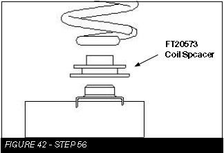
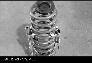
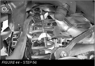
56. Locate FT20573 Coil Spacers and place onto the coil perch on the axle. With the floor jack under the rear axle, attach your coil spring compressor onto the new rear coil spring and compress the coil 1”-2”. Set the upper coil insulator on top of the coil spring and position the top of the coil into the frame pocket. Push the bottom of the coil spring onto the new spacer and raise the floor jack under the axle to hold the coil spring in position. Remove the coil spring compressors. Repeat this with the opposite coil spring. USE CAUTION WHEN WORKING WITH COIL SPRING COMPRESSORS, THEY CAN BE UNDER EXTREME LOAD. SEE FIGURES 42-44
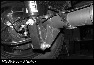
57. Reinstall the shocks onto the lower axle mounts using FT20673BK Rear Shock Bracket Torque to 100 ft-lbs. SEE FIGURE 45
58. Raise the floor jack supporting the rear axle and slide the upper mount of the track bar into the track bar bracket. Align the track bar with the hole and reinstall the factory bolt. Torque to 95 lbs.
59. Install tires and wheels and torque lug nuts to wheel manufacturer’s specifications. Turn front tires left to right and check for appropriate tire clearance. Note - Some oversized tires may require trimming of the front bumper & valance.
60. Check front end alignment and set to factory specifications. Readjust headlights.
61. Recheck all bolts for proper torque.
62. Recheck brake hoses, ABS wires and suspension parts for proper tire clearance while turning tires fully left to right.
63. Check the fluid in the front and rear differential and fill if needed with factory specification differential oil. Note - some differentials may expel fluid after filling and driving. This can be normal in resetting the fluid level with the new position of the differential/s.
64. Install Driver Warning Decal. Complete product registration card and mail to Fabtech in order to receive future safety and technical bulletins on this suspension.
Vehicles that will receive oversized tires should check ball joints and all steering components every 2500-5000 miles for wear and replace as required.
RETORQUE ALL NUTS, BOLTS AND LUGS AFTER 50 MILES AND PERIODICALLY THEREAFTER.


