 FREE 1 to 3-Day Delivery on Orders $149+ Details
How to Install Fabtech 4 in. Budget Lift System w/ Shocks on your Sierra
Installation Time
4 hours
Tools Required
- Basic Hand Tools
- Floor Jack
- Jack Stands
- Assorted Metric and S.A.E sockets, and Allen wrenches
- Torque Wrench
- Die Grinder
- Drill & Drill Bits

Shop Parts in this Guide
- PRE-INSTALLATION NOTES -
Read this before you begin installation-
WILL NOT WORK ON FACTORY ALUMINUM OR STAMPED STEEL SUSPENSIONS
Check all parts to the parts list above before beginning installation. If any parts are missing contact Fabtech at 909-597-7800 and a replacement part will be sent to you immediately.
Read all instructions thoroughly from start to finish before beginning the installation. If these instructions are not properly followed severe frame, driveline and / or suspension damage may occur.
Check your local city and state laws prior to the installation of this system for legality. Do not install if not legal in your area.
Prior to the installation of this suspension system perform a front end alignment and record. Do not install this system if the vehicle alignment is not within factory specifications. Check for frame and suspension damage prior to installation.
The installation of this suspension system should be performed by two professional mechanics.
Use the provided thread locking compound on all hardware.
Do not combine this suspension system with any other lift device or parts.
This suspension must be installed with Fabtech shock absorbers.
WARNING- Installation of this system will alter the center of gravity of the vehicle and may increase roll over as compared to stock.
For technical assistance call: 909-597-7800 or e-mail: [email protected]
OEM Wheels and tires cannot be used after the installation of this kit. Larger tire cannot be installed on the OEM wheels.
Vehicles that receive oversized tires should check ball joints, tie rods ends, pitman arm and idler arm every 2500-5000 miles for wear and replace as needed.
Requires cutting of fenderwell sheetmetal for use with 33” tires.
Suspension system will not work on vehicles equipped with factory auto ride suspension.
Verify differential fluid is at manufactures recommended level prior to kit installation. Installation of the kit will reposition the differential and the fill plug hole may be in a different position. (For example, if the manufacture recommends 3 quarts of fluid, make sure the diff has 3 quarts of fluid). Check your specific manual for correct amount of fluid.
Recommend Tires and Wheels:
Use 295/70R17 tire w/ 17x8 wheels w/ 4-1/2” BS w/ minor trimming
Use 275/65R18 tire w/ 18x8 wheels w/ 4-1/2” BS w/ minor trimming
Use 285/55R20 tire w/ 20x9 wheels w/ 5” BS w/ minor trimming
- INSTRUCTIONS -
FRONT SUSPENSION
1. Disconnect the negative terminal on the battery. Jack up the front end of the truck and support the frame rails with jack stands. NEVER WORK UNDER AN UNSUPPORTED VEHICLE! Remove the front tires.
2. Starting on the driver side of the truck, remove the bolt attaching the brake line tab to the spindle.
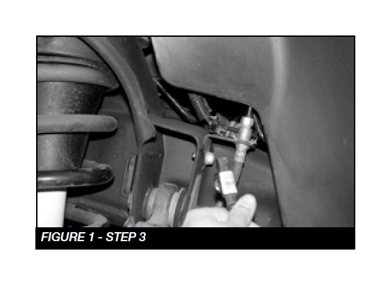
3. Follow the wheel speed sensor wire from frame rail plug. Separate the wire from the upper control arm. SEE FIGURE 1
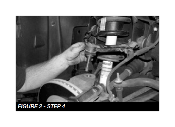
4. Remove the nuts securing the tie rod and upper arm ball joints to the spindle. Separate both joints from the spindle and remove the upper control arm and tie rod from the spindle. SEE FIGURE 2
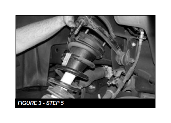
5. Remove the factory coil over and save. SEE FIGURE 3
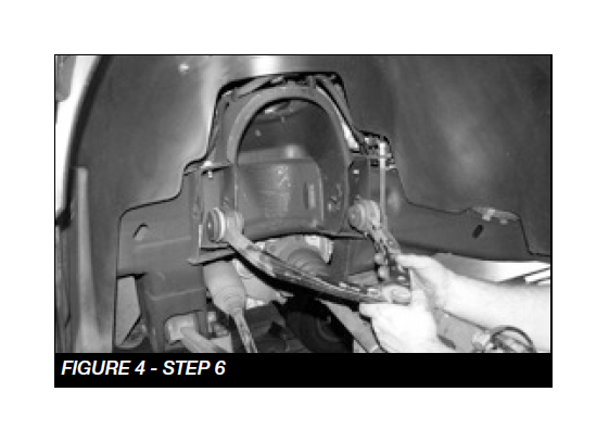
6. Remove the upper control arm form the vehicle and save the factory hardware. SEE FIGURE 4
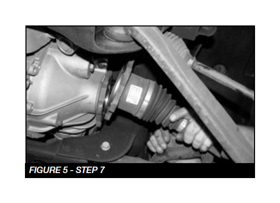
7. Remove the factory CV shaft from the differential drive flange on both sides of vehicle. SEE FIGURE 5
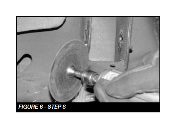
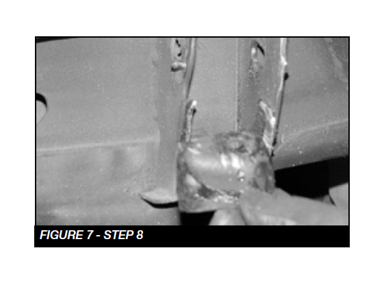
8. Using a die grinder remove the factory droop stop off the control arm pocket. SEE FIGURES 6-7
9. Using a die grinder, partially cut the brake line bracket. This will allow the bracket to be bent and removed from the brake line. Be careful not to damage brake hose.
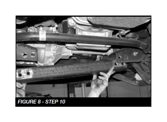
10. Remove the factory rear cross member and retain factory hardware. SEE FIGURE 8
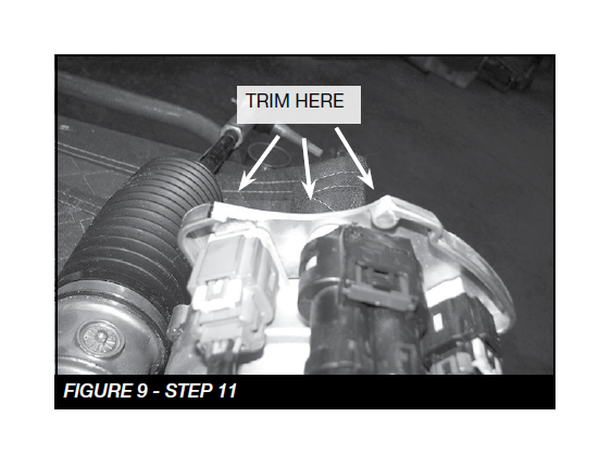
11. Due to vehicle variances, the steering will need to be removed and trimmed on the driver side where the wiring harnesses are located. SEE FIGURE 9
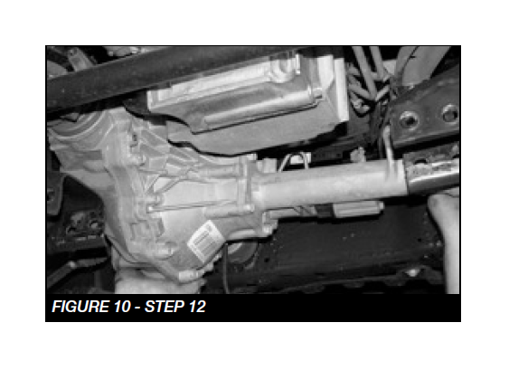
12. Disconnect the drive shaft from the front differential solenoid wiring. Disconnect the differential vent tube and remove the diff. SEE FIGURE 10
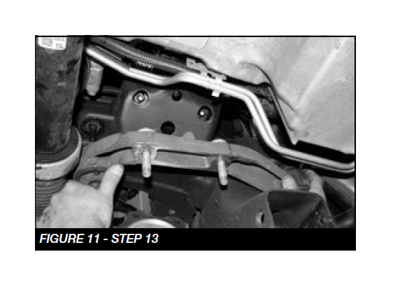
13. Locate the factory passenger side diff mount and remove. SEE FIGURE 11
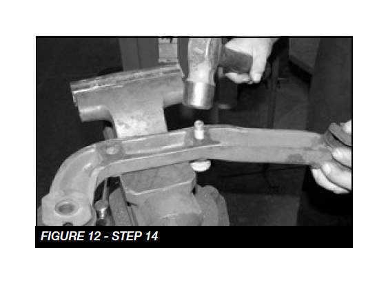
14. Remove the factory studs from the differential mount and reinstall the differential mount. SEE FIGURE 12
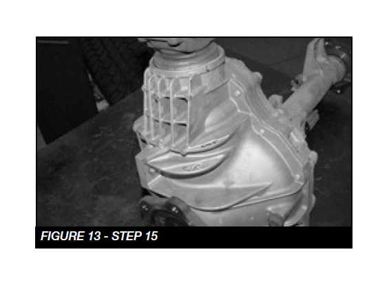
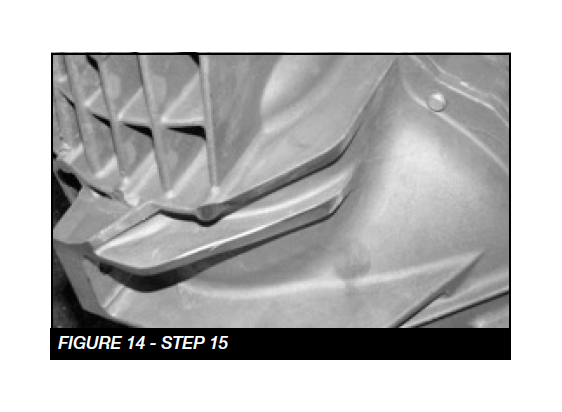
15. Locate the factory diff and cut off the driver side rear cooling fins. SEE FIGURES 13-14
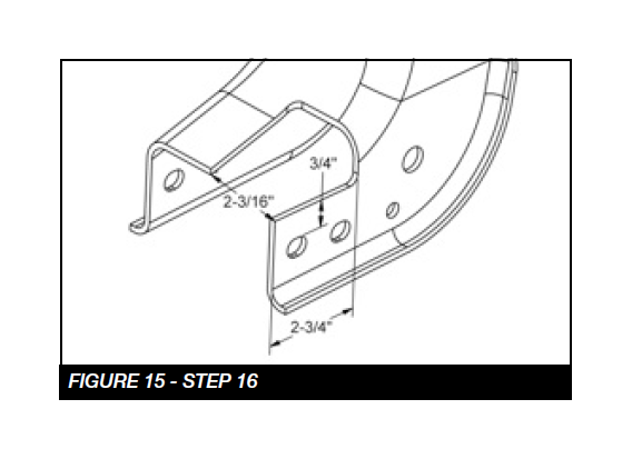
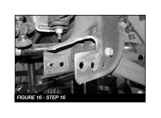
16. Locate the factory rear driver lower control arm pocket / cross member mount. Using a die grinder remove the material shown in the diagram below. SEE FIGURES 15-16
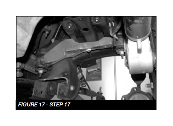
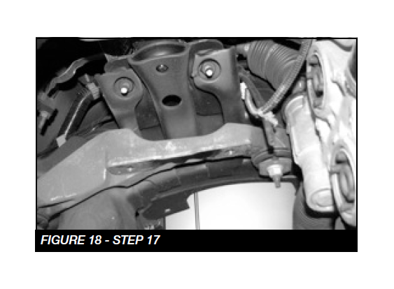
17. Locate the factory driver side Diff mount. Using a die grinder remove the locating pin from the mount. SEE FIGURES 17-18
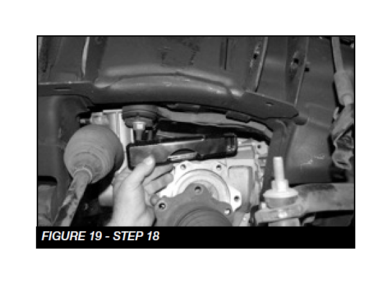
18. Locate the FT20625 driver side diff mount and the FT20626 passenger side diff mount. Staring on the driver side, remount the diff with two M12-1.75 x 70mm bolts. Torque to 100 ft-lbs SEE FIGURE 19
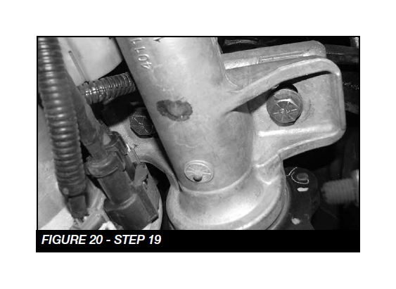
19. Using the passenger side differential mount, two ½”-13 x 4” bolts, nuts and washers, mount the passenger side of the differential. NOTE: Run the bolts from the bottom up. Torque the 1/2” bolts to 127 ft-lbs. SEE FIGURE 20
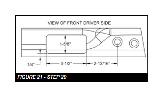
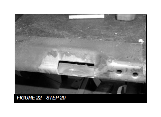
20. Locate the factory rear cross member. Using a die grinder remove the material from the driver side shown in the diagram. SEE FIGURES 21-22
21. Reinstall Factory rear crossmember. Torque bolts to 100
ft-lbs.
22. Reconnect the drive shaft, differential vent tube and
solenoid with factory hardware. Torque to 17 ft-lbs.
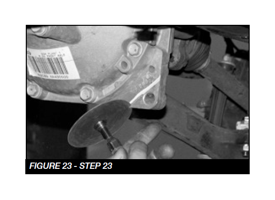
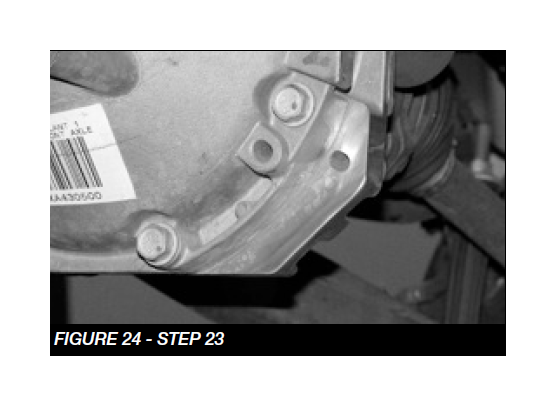
23. Trim the front of the differential to clear the new skid plate.
SEE FIGURES 23-24
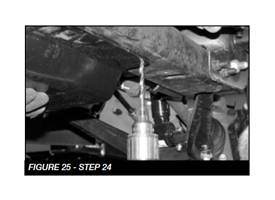
24. Locate the FT20627BK skid plate and the two 3/8”- 16x3/4” self taping bolts. Mount the skid plate to the factory front cross member using two of the factory front bolts. With front of the skid plate mounted, use the back two holes in the skid plate for a drill guide. Drill two 5/16” pilot holes and install the two 3/8” self taping bolts. Torque to 21 ft-lbs. Be careful not to over torque. SEE FIGURE 25
25. Locate the FT20558BK driver upper control arm and one FT20619 ball joint, two FTS1001bushings, two FT1002 bushings, two grease zerks FT84, and two FT1500-6-101 sleeves.
26. Install one FTS1001 bushing, one FT1002 bushing and a FT1500-6-101 sleeve zerk in each barrel. Use the FTLUBE urethane lube on each bushing.
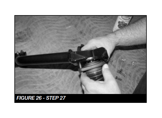
27. Install the ball joint onto the control arm with the supplied 5/16”-18 x 1” bolts, washers and nuts from the hardware kit. Lube ball joint through zerk fittings. Torque to 29 ftlbs. SEE FIGURE 26
28. Repeat steps 23-25 using FT20559BK for passenger side.
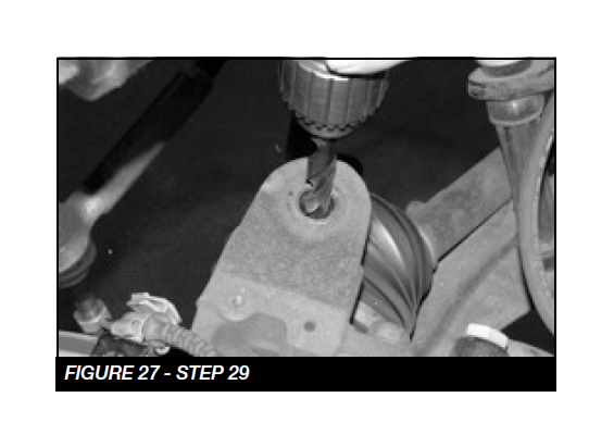
29. Using a 1/2” drill, chase out the end of the upper ball joint tapper on the spindle. SEE FIGURE 27
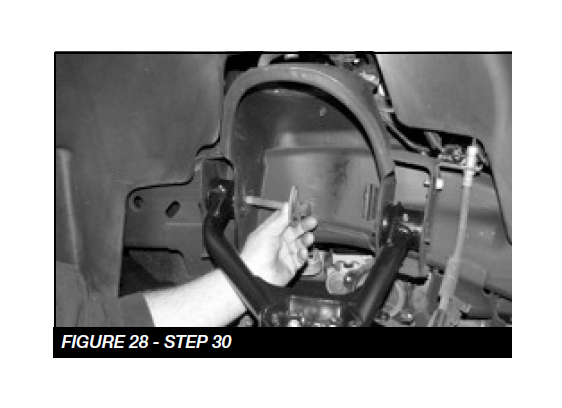
30. Install the upper control arm in to the frame using factory hardware and leave loose at this time. SEE FIGURE 28
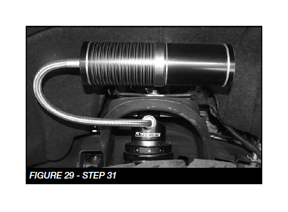
31. If installing Dirt Logic coilover, P/N FTS825282 or FT820282D & P do so at this time using hardware provided with that shock. Install the Coilover so it offsets towards the rear of the truck. NOTE: See Figure 29 for resi mount orientation. Otherwise, continue with Step 31 with the factory shock.
32. Locate the factory coil over and remove the sheet metal nut from the lower bar pin.
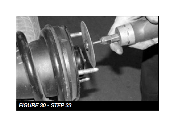
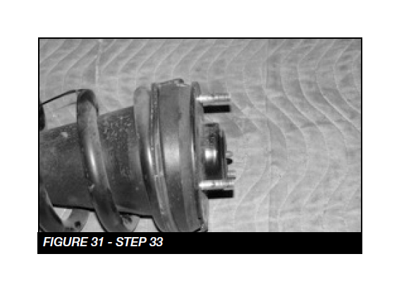
33. Trim a 1/4” off the studs on the top side of the coil over. SEE FIGURE 30-31
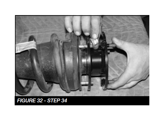
34. Install the FT20560BK coil spacer using the factory nuts and torque to 37 ft-lbs. SEE FIGURE 32
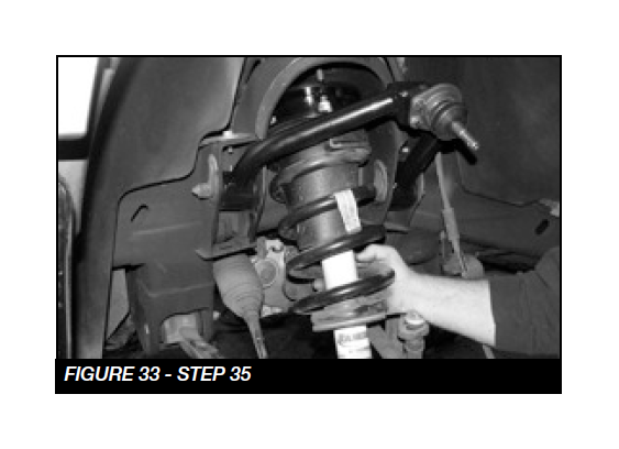
35. Locate the three 7/16” nylock nuts and install the coil over into the upper shock mount. Leave loose at this time. SEE FIGURE 33
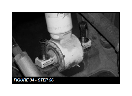
36. Locate the two 7/16”-14 x 2-1/4” bolts, nuts and washers and install the lower bar pin mount onto the lower control arm. Torque the upper and lower bolts to 83 ft-lbs. SEE FIGURE 34
37. Install the upper ball joint in to the spindle and torque to 90 ft-lbs and the pivot bolts to 184 ft-lbs.
38. Reinstall the CV shaft and torque to 58 ft-lbs.
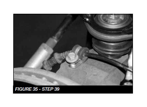
39. Install the FT clamp on top of the spindle to hold the wheel speed sensor wire. SEE FIGURE 35
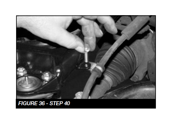
40. Use an FTCLAMP, 1/4”-20 x 1” bolt, nut, and washer to connect the brake line to the control arm. SEE FIGURE 36
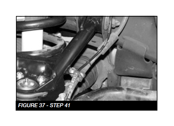
41. Reconnect the wheel speed sensor and zip tie to the brake line. SEE FIGURE 37
42. Repeat steps 3-39 on passenger side of vehicle where applicable.
REAR SUSPENSION
(FOR SUV REAR SUSPENSION SKIP TO STEP 50)
43. Locate the FTBK15 blocks and the four FT1500U u-bolts. With the factory block and u-bolts removed and the rear axle clear of the leaf spring, make sure the block will fully seat onto the leaf spring and the spring pad of the rear axle housing with the wide end of the block to the rear of the vehicle. On the leaf spring make sure the center pin head will seat fully into the hole of the block allowing the top surface of the block to rest against the leaf spring. Install the new u-bolts with washers and nuts from the FT916H hardware kit and torque to 184 ft-lbs. Note – The Vehicle’s stance will be level with the Fabtech block. To achieve a higher rear stance stack both factory and Fabtech blocks. Longer shocks or shock extensions are required for proper installation.
44. Install rear shocks using FTS7333 (Performance shocks), FTS6333 (Stealth Shocks) or FTS810152 (Dirt Logic shocks) with factory hardware. Torque to 100 ft-lbs.
45. Install tires and wheels and torque lug nuts to wheel manufacturer’s specifications. Turn front tires left to right and check for appropriate tire clearance. Note - Some oversized tires may require trimming of the front bumper & valance.
46. Check front end alignment and set to factory specifications. Readjust headlights.
47. Recheck all bolts for proper torque.
48. Recheck brake hoses, ABS wires and suspension parts for proper tire clearance while turning tires fully left to right.
49. Check the fluid in the front and rear differential and fill if needed with factory specification differential oil. Note - some differentials may expel fluid after filling and driving. This can be normal in resetting the fluid level with the new position of the differential/s.
50. Install Driver Warning Decal. Complete product registration card and mail to Fabtech in order to receive future safety and technical bulletins on this suspension.
51. SUV REAR SUSPENSION
52. Jack up the rear end of the vehicle and support the frame rails with jack stands.
53. Using a floor jack, raise the differential just enough to slightly compress the rear shocks. Remove the bolts securing the bottom of the shocks to the axle. (if equipped with air ride system, unplug the electrical and air line connections). Remove the upper pivot bolt that attaches the track bar to the frame bracket.
54. Lower the floor jack to release the coil springs. Remove the coil springs from the vehicle and save with the rubber upper coil insulator.
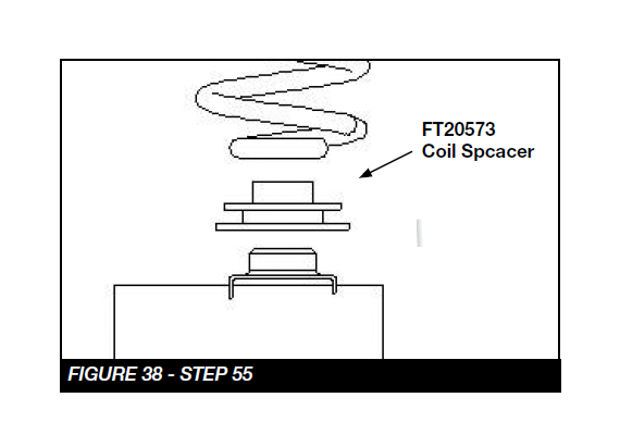
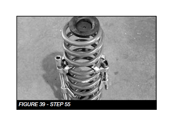
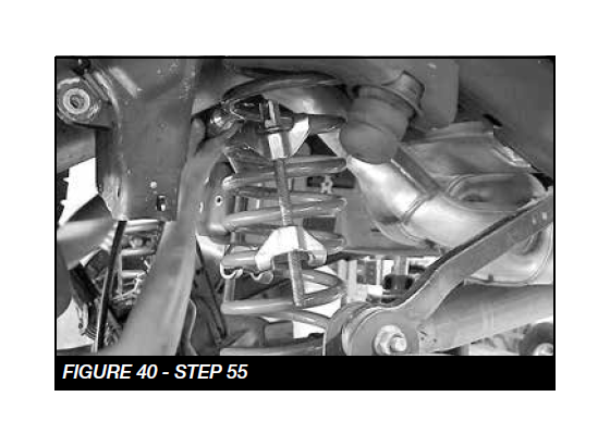
55. Locate FT20573 Coil Spacers and place onto the coil perch on the axle. With the floor jack under the rear axle, attach your coil spring compressor onto the new rear coil spring and compress the coil 1”-2”. Set the upper coil insulator on top of the coil spring and position the top of the coil into the frame pocket. Push the bottom of the coil spring onto the new spacer and raise the floor jack under the axle to hold the coil spring in position. Remove the coil spring compressors. Repeat this with the opposite coil spring. USE CAUTION WHEN WORKING WITH COIL SPRING COMPRESSORS, THEY CAN BE UNDER EXTREME LOAD. SEE FIGURES 38-40
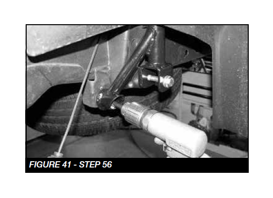
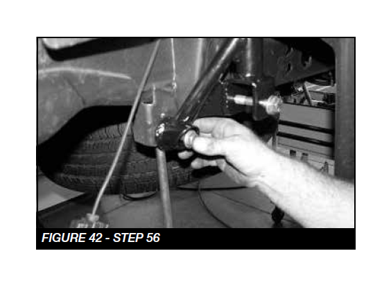
56. Working from the drivers side, remove the sway bar end link bolt and save. NOTE: 2015-UP MODELS- Locate FT1599-1-2D (Shock Drop Bracket). Slide the shock mount extension into the original frame mount and insert one of the factory shock bolts and hardware through the original shock mount side and hand tighten. Re-install the sway bar bolt through the new shock bracket. Torque the sway bar bolt to 75ft-lbs and the top bracket bolt to 85ftlbs. SEE FIGURES 41-42
57. Repeat step 55 for the passenger side of the vehicle.
58. Install rear shocks using FTS7299 Performance shocks, FTS6299 Stealth Shocks or FTS810032 Dirt Logic shocks with factory hardware. Torque to 100 ft-lbs.
59. Install tires and wheels and torque lug nuts to wheel manufacturer’s specifications. Turn front tires left to right and check for appropriate tire clearance. Note - Some oversized tires may require trimming of the front bumper & valance.
60. Check front end alignment and set to factory specifications. Readjust headlights.
61. Recheck all bolts for proper torque.
62. Recheck brake hoses, ABS wires and suspension parts for proper tire clearance while turning tires fully left to right.
63. Check the fluid in the front and rear differential and fill if needed with factory specification differential oil. Note - some differentials may expel fluid after filling and driving. This can be normal in resetting the fluid level with the new position of the differential/s.
64. Install Driver Warning Decal. Complete product registration card and mail to Fabtech in order to receive future safety and technical bulletins on this suspension.
Vehicles that will receive oversized tires should check ball joints and all steering components every 2500-5000 miles for wear and replace as required.
RETORQUE ALL NUTS, BOLTS AND LUGS AFTER 50 MILES AND PERIODICALLY THEREAFTER.


