FREE 1 to 3-Day Delivery on Orders $149+ Details
How to Install FOX 2.0 Performance Series Coil-over IFP Shock for 0-2 in. Lift - Front on your Dodge Ram

Shop Parts in this Guide
WARNINGS
• FOX direct-replacement shocks should always be installed as a pair for maximum performance.
• Proper installation and service procedures are essential for the safe and reliable installation of chassis parts, requiring the experience and tools specially designed for this purpose. Installation and maintenance procedures for this product must be performed by a qualified service technician, to avoid potentially unsafe vehicle handling characteristics, which may result in SERIOUS INJURY or DEATH.
• Modifying your vehicle’s suspension will change the handling characteristics of your vehicle. Under certain conditions, your modified vehicle may be more susceptible to loss of control or rollover, which can result in SERIOUS INJURY or DEATH. Thoroughly familiarize yourself with the modified vehicle handling characteristics before any rigorous vehicle operation. Wear body protective gear including head protection when appropriate.
Installation of vehicle roll bars or cage is highly recommended.
• FOX direct-replacement shocks are gas-charged and are highly pressurized. Placing shocks in a vise or clamp, applying heat, or attempting to open or service the shock without the proper tools and training can result in SERIOUS INJURY or DEATH. Do not attempt to modify, puncture or incinerate a FOX direct-replacement, coil-over shock absorber.
• Any attempt to misuse, misapply, modify, or tamper with any FOX product voids any warranty and may result in SERIOUS INJURY or DEATH.
GUIDELINES
• Always use a chassis lift for the installation of shocks, and make certain that the raised vehicle is securely attached to the lift to prevent the vehicle from slipping, falling, or moving during the installation process.
• DO NOT install any FOX product without the necessary special tools, expertise and chassis lift, or you will subject yourself to the risk of SERIOUS INJURY or DEATH. If you elect to not use a chassis lift (which election may result in SERIOUS INJURY or DEATH), ensure that the vehicle is on level ground, that all tires on the ground during installation are blocked to prevent vehicle movement, that at least two tires are on the ground at all times, and that adequately secured jack stands are used to support the vehicle. NEVER get under the vehicle until you have checked to ensure that the vehicle will be stable during installation.
• FOX direct-replacement shocks are designed to fit your vehicle’s shock mounts with no modifications with the exception of reservoir placement on specific models and applications.
• To adjust the ride height, first lift the vehicle (refer to the INSTALLATION GUIDELINES for instructions on how to properly lift the vehicle). After properly lifted, loosen the pinch bolt securing the main spring retainer (Loosen bolt until it spins freely, DO NOT remove bolt!). Using a spanner wrench, adjust the main spring retainer as required. If shocks have locking rings, loosen the top lock ring and adjust main spring retainer as needed. Once set, retighten the top lock ring against the main spring retainer. IT IS HIGHLY RECOMMENDED TO USE A SPRING COMPRESSOR WHEN MAKING ANY TYPE OF PRE LOAD ADJUSTMENT
INSTRUCTIONS -FRONT
Medium-strength thread-lock (blue Loctite®) is recommended on all bolts.
1. Please read the installation guidelines for instructions on how to properly lift and secure the vehicle.
2. Record the front vehicle ride height to ensure proper lift is attained after kit is installed. You will be able to make preload adjustments if needed once the shock assembly is installed. (Spanner wrench required) READ INSTALLATION GUIDELINES ON HOW TO PROPERLY ADJUST PRELOAD
3. Remove both front wheels.
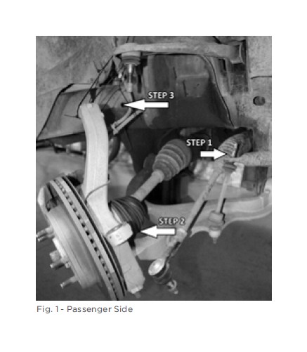
4. Disconnect sway bar at the lower control arm on both sides. (Fig. 1 - Step 1)
5. Disconnect both outer tie rod ends from spindle steering arm. (Fig.1 - step 2)
6. Disconnect both upper control arms from spindle steering arm. Be careful not to damage any electric wires or brake lines. (Fig.1 - Step 3)
7. Remove the (3) top nuts that secure the stock shock assembly to the vehicle. DO NOT remove center nut; doing so will release the spring from the stock assembly and could result in SERIOUS INJURY or DEATH!
8. Remove the (1) bolt and nut connecting the shock to the lower control arm. (Do not discard bolt and nut as it will be used with your new FOX coil-over kit)
9. Remove the stock shock assembly. You may need to use a pry bar to lower the suspension enough to remove the stock shock. Be careful not to damage any brake lines or electrical wires.
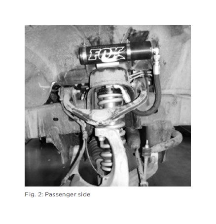
10. Install the new coil-over assembly. With remote reservoir models make sure that the hoses are facing outward and towards the front of the vehicle. (Fig.2) Connect the top shock hat to the vehicle using the bolts and washers provided or with Performance Series models connect the top shock hat to the vehicle using the nuts and washers provided. Tighten all three bolts/nuts to 24 ft*lbs. (you will need to remove the outer center bolt to install the reservoir bracket in step 12)
11. Connect the shock assembly to the lower control arm, reusing the stock bolt and nut. Torque to factory specifications.
12. On the external reservoir models, install the reservoir bracket by placing on top of the vehicle coil-over bucket and align the bracket center hole with the outer center hole of the shock top hat, install supplied bolt and torque to 24 ft*lbs.
13. On the external reservoir models, install the reservoir onto reservoir bracket using two supplied clamps. Utilize the slots in the bracket to locate clamps. Do not feed clamps through the slots in the brackets.
14. Reconnect upper control arm to steering knuckle on both sides and torque to factory specifications.
15. Reconnect the sway bar on both sides and torque to factory specifications.
16. Reconnect the outer tie rod on both sides and torque to factory specifications
17. Check that the suspension has proper clearance by steering completely in both directions.
18. Reinstall both front wheels and torque to factory specifications.
19. Set vehicle back on the ground and drive it back and forth several feet to allow the suspension to settle. Now measure ride height and make adjustments if necessary. READ INSTALLATION GUIDELINES ON HOW TO PROPERLY ADJUST PRELOAD
20. It is highly recommended that you have your wheel alignment checked.
INSTRUCTIONS - REAR
Medium-strength thread-lock (blue Loctite®) is recommended on all bolts.
1. Please read the installation guidelines for instructions on how to properly lift and secure the vehicle.
2. Remove fender liners from each side of vehicle.
3. Remove stock shocks. It may be necessary to support or raise the vehicle axle in order to remove bolts and for installation of new shock. (Do not discard bolts and nuts, as they will be used with your new Shock.)
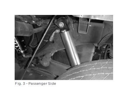
4. Install new shock, reusing factory bolts and nuts. On external reservoir models, make sure that hoses are facing toward the front of the vehicle on both driver and passenger sides. Torque to factory specifications. (Fig. 3)
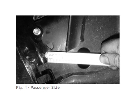
5. For external reservoir models, install supplied reservoir brackets onto the vehicle frame as shown (Fig 4). Align lower bracket hole approximately 1.5’’ from factory bed mount bracket toward the front of the vehicle and vertically 2’’ above welded seam on side of frame. Mark hole and drill a 7/32’’ pilot hole, then secure the reservoir bracket to the frame with one of the supplied 1/4’’ self tapping screws. Angle bracket approximately 45 degrees toward the front of vehicle. Repeat marking and drilling the upper bracket hole and installing self tapping screw.
6. On external reservoir models, install the reservoir onto the reservoir bracket using the supplied hose clamps. Utilize the slots in the bracket to locate clamps. Do not feed clamps through the slots in the brackets.
7. Reinstall fender liners.