 FREE 1 to 3-Day Delivery on Orders $149+ Details
How to Install Fabtech 6 in. Basic Lift System w/ Shocks on your Dodge Ram
Tools Required
- Floor Jack
- Jack Stands
- Torque Wrench
- Drill/Drill Bits
- Arbor Press or vise
- Sawzall
- Assorted Metric and S.A.E sockets
- Allen wrenches
- Die Grinder w/ Cutoff Wheel and Grinding Wheel
- Large Dead Blow Hammer

Shop Parts in this Guide
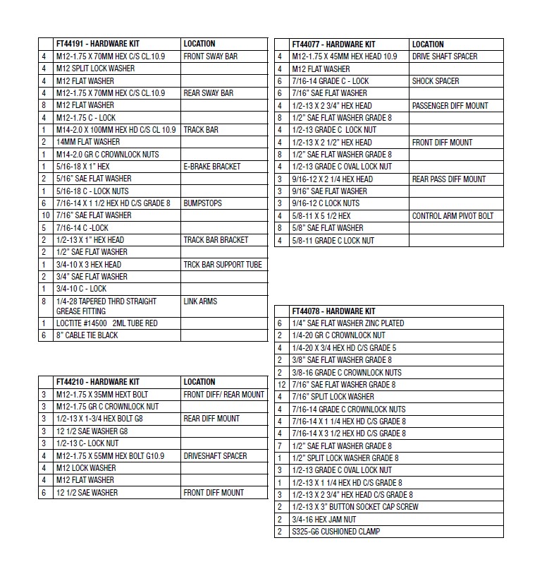
- PARTS LIST -
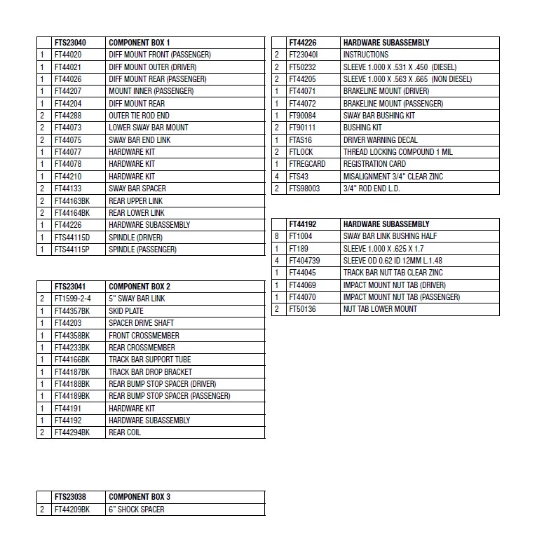
- PARTS LIST -
- INSTRUCTIONS -
FRONT SUSPENSION
1. Disconnect the negative terminal on the battery.
2. Jack up the front end of the truck and support the frame rails with jack stands. NEVER WORK UNDER AN UNSUPPORTED VEHICLE! Remove the front tires.
3. Remove the factory transfer case skid plate and discard.
4. Disconnect the front drive shaft from the differential and discard the hardware. (Do not allow to hang freely)
5. Locate the sway bar end links and disconnect them from the lower control arms and the sway bar. Discard the end links and hardware. Leave the factory sway bar on the truck attached to the frame mounts.
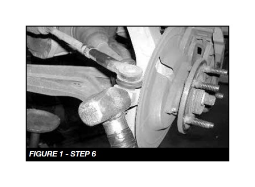
6. Working from the driver side of the vehicle, disconnect the tie rod end from the steering knuckle by striking the knuckle to dislodge the tie rod end. Do not remove the factory Jam Nut from the inner tie rod. Discard the outer tie rod as a new Fabtech tie rod end will be installed later. SEE FIGURE 1
7. Remove the brake caliper and place it next to the frame. Do not overstretch the brake hose when doing so. DO NOT LET THE BRAKE CALIPER HANG FROM THE BRAKE HOSE. Retain the hardware for reinstallation. Remove the brake rotor and save. Unplug the ABS wire at the plug behind the inner fender well and remove the ABS line clamp were it is attached to the steering knuckle.
8. Remove the axle nut from the center of the hub and save.
9. Remove the upper and lower ball joint nuts and save. Using a large hammer, strike the steering knuckle to dislodge the ball joints from the steering knuckle. USE CARE NOT TO DAMAGE THE THREADS ON THE BALL JOINTS. Remove the steering knuckle from the truck.
10. Remove the bolts attaching the hub bearing to the steering knuckle and save. Remove hub assembly along with the ABS sensor wire and dust shield from the steering knuckle as one and save. NOTE: Do not disconnect the ABS sensor from the hub at anytime. Note position of the hub in the steering knuckle for later reinstallation. Discard the steering knuckle.
11. Remove the three upper shock assembly bolts from the truck and save. Remove the lower shock bolt and save. Remove the shock assembly from the truck and save. The factory shock assembly will be reused if you are installing the 6” Basic System. If you are installing the 6” Performance System, you can discard the factory shock assembly and hardware.
12. Remove the factory lower control arm bolts / alignment cams and save. Remove the lower control arm and save.
13. Remove the C.V. half shaft from the differential. This can be done by using a rubber mallet and striking the backside of the inner C.V. joint housing. Save the half shaft. NOTE: The differential may leak some gear oil.
14. Repeat steps 6-13 on the passenger side of the truck.
15. Remove the factory rear crossmember from the truck and discard the crossmember and hardware.
16. IF INSTALLING ON VEHICLES EQUIPPED WITH GAS ENGINE PROCEED TO STEP 19.
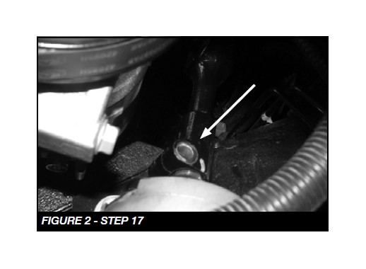
17. FOR DIESEL ENGINES ONLY: Removal of steering rack is required to access bolt on top of differential. Unplug connectors on steering rack. Remove bolt that secures the steering shaft to the rack SEE FIGURE 2
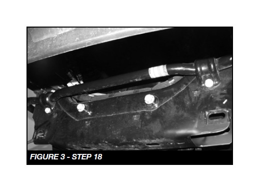
18. Supporting the steering rack, Remove the (2) bolts. SEE FIGURE 3. Gently remove the rack and set aside.
19. Support the differential with a floor jack or transmission jack, disconnect solenoid and remove the differential from the truck. Save the hardware some will be re-used.
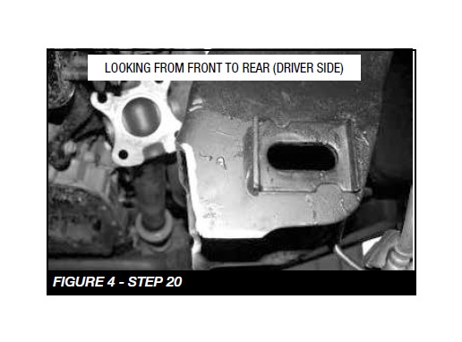
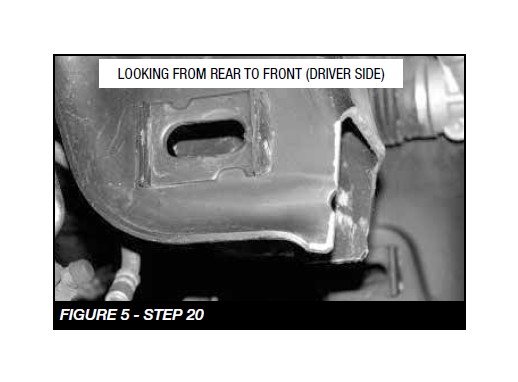
20. Locate the driver side rear lower control arm mount where the factory rear crossmember was previously removed. As shown in the picture below, using a die grinder cut a 1” section from the side of the frame and ½” from the bottom of the frame. SEE FIGURES 4-5.
DUE TO VARIANCES IN EACH TRUCK, ADDITIONAL CUTTING / GRINDING MAY BE REQUIRED FOR PROPER FITMENT OF THE CROSSMEMBERS AND DIFFERENTIAL. USE THESE MEASUREMENTS AS A STARTING POINT AND CLEARANCE THE FRAME POCKETS AS NEEDED FOR PROPER FITMENT OF THE CROSSMEMBERS & DIFFERENTIAL.
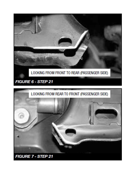
21. Locate the Passenger side rear lower control arm mount where the factory rear crossmember was previously removed. As shown in the picture below cut a 1” section from the side of the frame and ½” from the bottom of the frame. SEE FIGURES 6-7
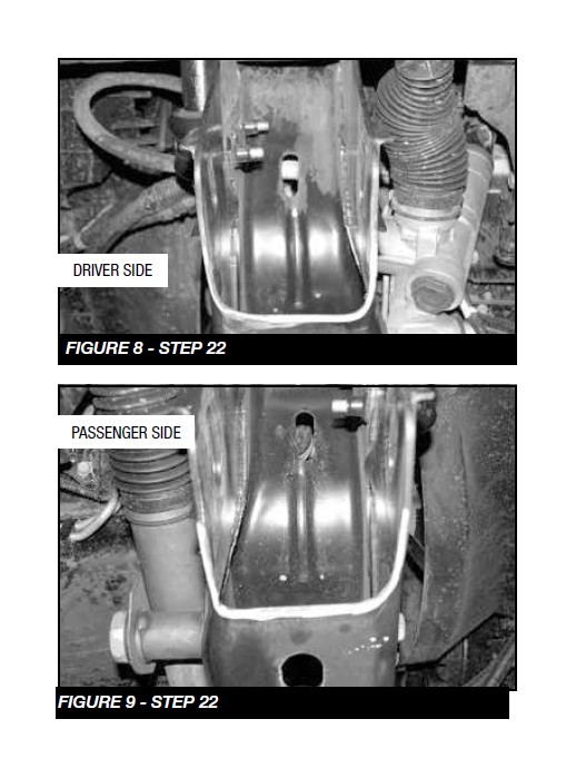
22. Locate the factory front lower control arm pockets. Grind ¼” section from both pockets as shown in the photo. SEE FIGURES 8-9
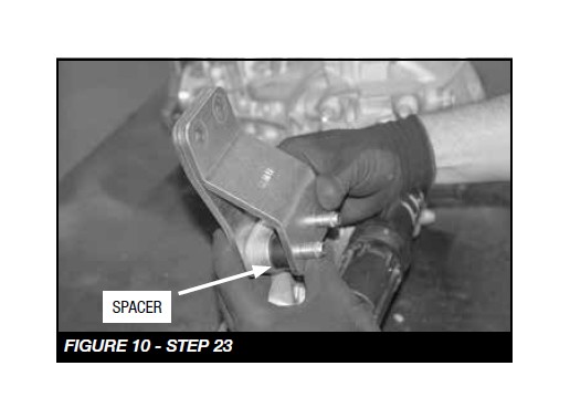
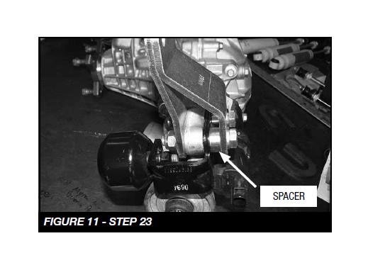
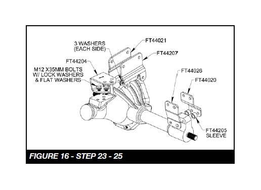
23. Locate FT44020 and FT44026 passenger side differential mounts. Using the supplied ½” x 2 ¾” hardware attach the brackets to the differential using (FOR GAS ENGINES) FT44205 (1.000X.563X.665-larger spacer). The spacers will provide space between the FT44020 bracket and the differential. SEE FIGURE 10. Leave loose at this time. FOR DIESEL MODELS: Locate FT50232 (1.000X.531X.450 smaller spacer) and remount the harmonic dampener to the the differential. SEE FIGURE 11.
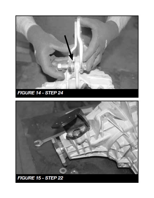
24. Locate FT44021, FT44207 Driver front diff mounts and 6 1/2” SAE Washers. Using the supplied ½”X 2 ½” hardware attach the brackets to the differential as shown in the diagram. Leave loose at this time. SEE FIGURES 12-14
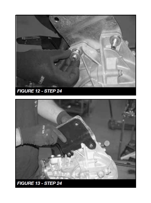
25. Locate FT44204 Driver rear diff mount. Using the M12x35mm bolts, lock washers and flat washers attach the bracket to the original diff mount mount. Leave loose at this time. SEE FIGURES 13-14
26. Install the differential back into the truck attaching the new Fabtech drop brackets to the factory frame mounts. Use the factory hardware on the passenger side bracket and use the supplied ½ -13 x 1 ¾ bolt, nuts, and washer on the driver rear brackets. DO NOT mount the Driver front diff mount at this time. LEAVE ALL HARDWARE LOOSE AT THIS TIME.
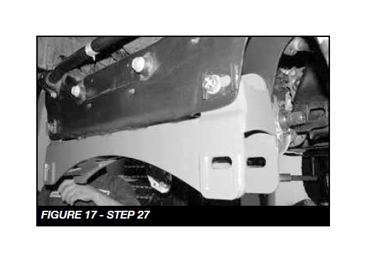
27. Locate FT44358BK front crossmember and install it into the front lower control arm pockets using the supplied 5/8” x 5 ½” bolts, nuts, and washers. Leave loose at this time. SEE FIGURE 17
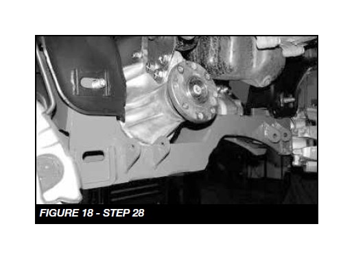
28. Locate FT44089BK rear crossmember and install it into the frame pockets using the 5/8” x 5 ½” bolts, nuts, and washers. Leave loose at this time. SEE FIGURE 18
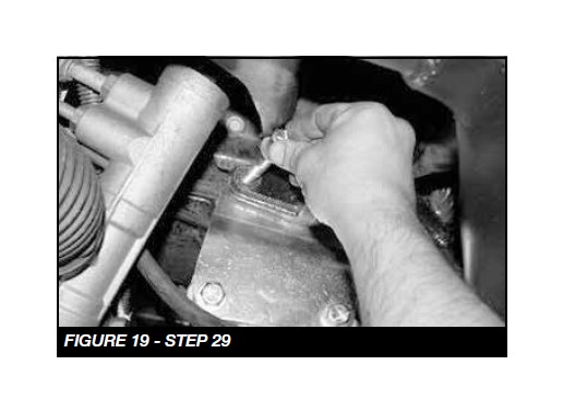
29. Install the factory hardware on the driver side front diff bracket. Torque all differential hardware to 100 ft lbs. SEE FIGURE 19
30. DIESEL MODELS ONLY: Once the differential is in and torqued, proceed with re-installing the steering rack. Use steps 17,18 in reverse order. Torque the steering shaft bolt to 36 ft-lbs. and the (2) crossmember bolts to 235 ft-lbs.
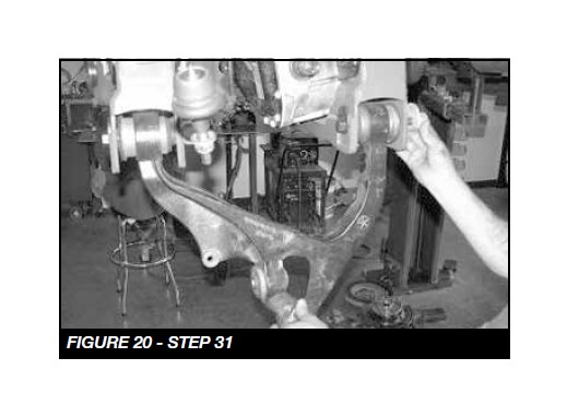
31. Working from the driver side of the truck, install the factory lower control arm to the Fabtech crossmembers using the original alignment cam bolts. Leave loose at this time. SEE FIGURE 20
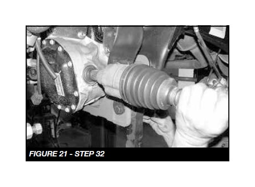
32. Install the C.V. half shaft back onto the differential by pushing the half shaft onto the splines until the snap ring locks. SEE FIGURE 21
FOLLOW STEPS 33-34 FOR BASIC KIT ONLY. IF INSTALLING THE PERFORMANCE SYSTEM WITH DIRT LOGIC 2.5 COILOVERS, INSTALL THE COILOVER SO IT IS OFFSET AWAY FROM THE AXLE.
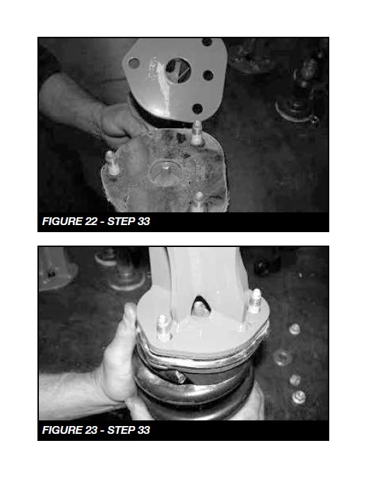
33. Locate the previously removed shock assembly and attach FT44209BK spacer to the top of the shock assembly using the stock hardware. Use a small amount of the supplied thread locking compound on the supplied shock to spacer hardware. Torque to 35 ft-lbs. You will need to mount the spacer so that it aligns properly with the coilover. SEE FIGURES 22-23
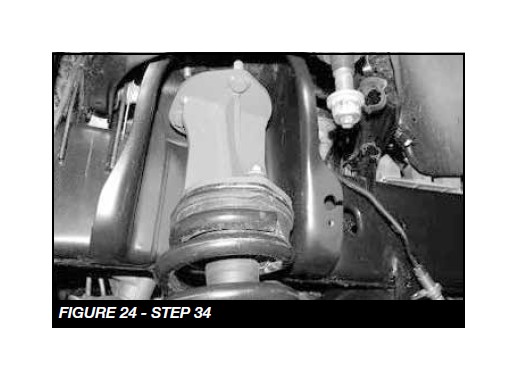
34. Install the complete shock assembly into the truck attaching the three upper bolts first using the supplied 7/16” C-lock and flat washers, leave loose. Torque upper hardware to 83 ft. lbs. SEE FIGURE 24
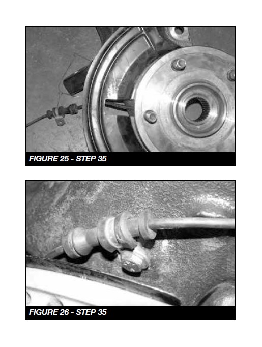
35. Locate FT44115D (driver) Steering Knuckle. Attach the previously removed hub bearing and dust shield to the knuckle in the same position as when removed using the original hardware and a small amount of the supplied thread locking compound on each bolt. Torque to 95 ft. lbs. Use the supplied adel clamp, and ¼” x 3/4” hardware and a small amount of thread locking compound and attach the A.B.S. line to the front of the knuckle. Torque to 10 ft-lbs. SEE FIGURES 25-26
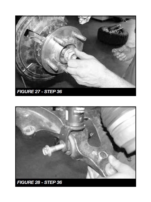
36. Attach the steering knuckle to the lower ball joint first, and then slide the C.V. shaft end through the hub bearing, followed by the upper ball joint to the steering knuckle. Torque the lower ball joint nut to 82 ft-lbs and the upper ball joint nut to 50 ft lbs. Using the original C.V. axle nut, attach the C.V. axle to the hub assembly. Torque to 100 ft lbs. Then attach the lower shock mount to the original mount on the lower control arm using the original hardware and torque to 90 ft.-lbs. SEE FIGURES 27-28
37. Repeat steps 35-40 on Passenger side of truck.
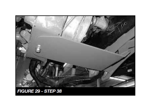
38. Locate FT44019BK skid plate and attach to the front crossmember using the supplied ½” X 2 ¾” bolt, nut, and washer, and to the rear crossmember using the supplied ½” x 1 ¼” bolt and flat and split washer. Torque to 90 ftlbs. SEE FIGURE 29
39. Torque the Fabtech crossmember bolts to 100 ft lbs and control arm pivot bolts / Alignment Cams to 110 ft. lbs. Set the cams in the middle of their adjustment.
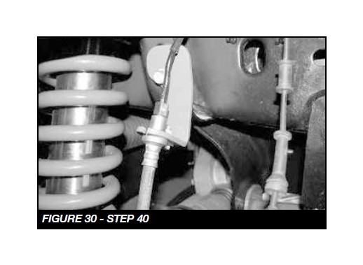
40. Locate the factory brake line in the coilover tower. Carefully cut the tower to remove the brake line. Remove the bracket from the frame saving the hardware. Carefully pull the brake line down from the frame approximately 4” (use care to not damage the hard line). Locate FT44071 Driver Brake Line Drop Mount Bracket and attach in original brake line mounting position. Locate the supplied ¼”x ¾” hardware and attach the factory brake line bracket to the new drop bracket. Torque to 10 ft-lbs. SEE FIGURE 30
41. Working from the drivers side, install the factory brake rotor and caliper. Use a small amount of the supplied thread lock compound on the caliper bolts and torque to 145 ft. lbs.
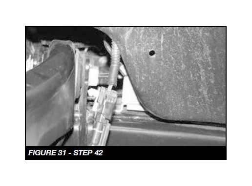
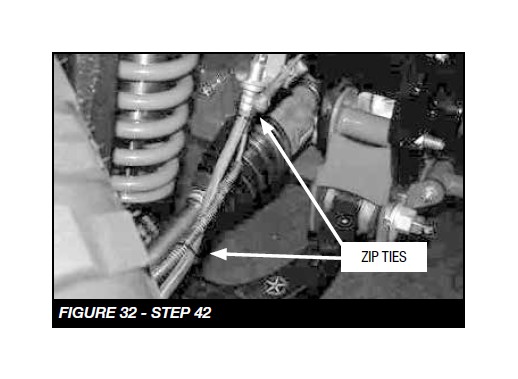
42. Locate the ABS plug on the inside of the fender well liner and remove the plastic clip holing it to the liner (use care not to damage connector). Route the ABS wire up from the knuckle parallel with brake lines and attach to the brake lines with the supplied zip ties. SEE FIGURES 31-32
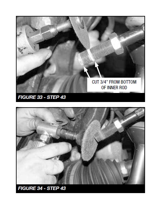
43. Locate the inner tie rod ends. Mark a 3/4” in from the end of the tie rod. Using a die grinder with a cutoff wheel, cut a 3/4” off of the end of the inner tie rod. Next using a die grinder with a sanding disc, clean up the threads on the inner tie rod so that the new Fabtech outer tie rod threads on without any binding of the threads. SEE FIGURES 33-34
44. Locate FT44288 tie rod end and thread it onto the factory inner tie rod end. Note: This is just a starting point, the toe adjustment will need to be set during the final alignment. Tighten the jam nut up to the tie rod end. Attach the tie rod end to the steering knuckle using the supplied 14mm nut. Torque to 85 ft lbs.
45. Repeat steps 44-48 on the passenger side of the truck.
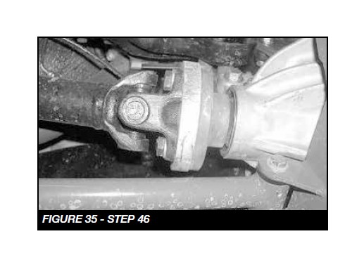
46. Locate FT44029 (09-11) or FT44203 (2012) front drive shaft spacer. Using the supplied thread-locking compound, 12mm bolts, and washer, attach the spacer and drive shaft to the front differential. Torque to 135 ft. lbs. SEE FIGURE 35
47. Locate FT44073 Lower Sway Bar Mounts and supplied 3/8” C-lock nuts and flat washers. Attach the mounts to the lower A-Arm in the factory sway bar location. Leave loose at this time.
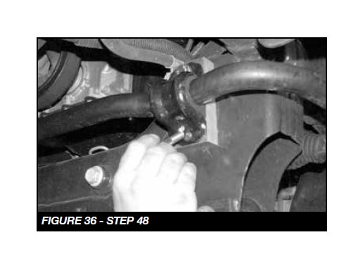
48. Loosen the four bolts holding the Sway Bar to the factory crossmember, Remove the two bolts from the driver side and discard. Locate and insert the FT44133 Sway Bar Spacer with the supplied M12-1.75 x 70mm bolts and washers. Repeat on the passenger side leaving hardware loose. SEE FIGURE 36
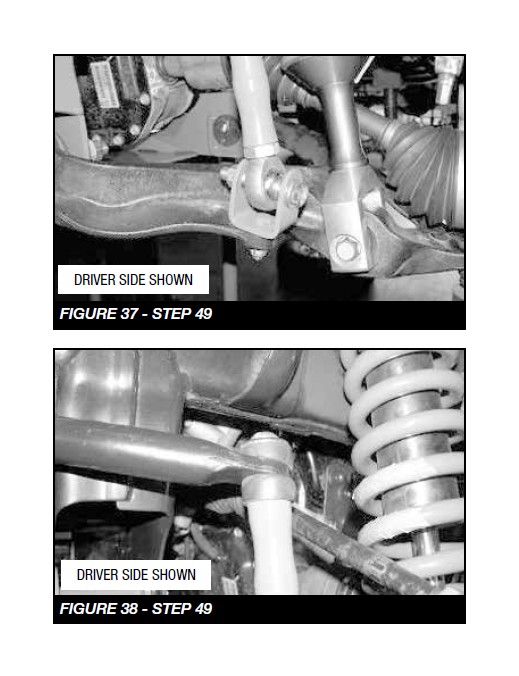
49. Locate both FT44075 Billet Sway Bar End Links and both of the supplied FTS98003 heim joints along with the supplied jam nuts. Thread the jam nuts all the way onto the heim joints, then thread the heim joints into the large end of the end links. Leave the jam nuts loose at this time. Locate the supplied ½” button head bolts and the FT90084 sway bar bushings along with the cup washers. Attach the bushing end of the sway bar end links to the factory sway bar, leave loose at this time. Attach the other end of the link using the supplied FT43 mis-alignments and supplied ½” x 2 ¾” hardware to the new mount on the lower arm. Torque upper and lower hardware to 60 ft. lbs. At times this may be easier to attach when the truck is completed and on the ground. SEE FIGURES 37-38
50. Install front tires and wheels. Torque lug nuts to wheel manufacturer’s specifications
Double Check That All Nuts And Bolts Are Now Tight Before Proceeding To The Rear.
REAR SUSPENSION
51. Disconnect the sway bar end links from the frame and sway bar; discard the end links and the hardware.
52. Remove the upper pivot bolt that attaches the track bar to the frame and save.
53. Remove the fender wells.
54. Using a floor jack, raise the differential just enough to slightly compress the rear shocks. Remove the bolts securing the top of the shocks to the frame.
55. Loosen and remove brake lines from frame, make sure they are clear and have enough slack when removing the rear coils.
56. Lower the floor jack to release the coil springs. Remove the coil springs from the vehicle and save the rubber coil insulators.
57. Remove the lower shock bolts and discard the shocks.
58. Remove the factory lower links arms. Discard the links and save the hardware.
59. Locate 44163BK Rear Upper Link, FT44164BK Rear Lower Links, FT1038 Bushing and FT77 Sleeves. Using an arbor press, press the bushings and sleeves (use supplied bushing lube) into each end of the links and install the supplied zerk fittings.
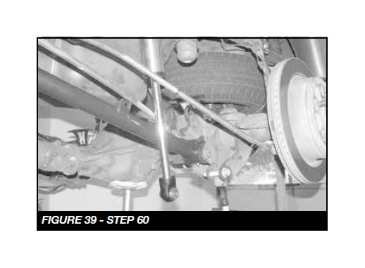
60. Install the new Lower Link Arms into the factory rear axle mounts with the factory hardware. Then attach the arm to the frame mounts also with the factory hardware. Leave loose at this time. SEE FIGURE 39
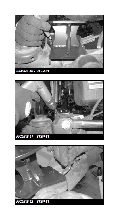
61. Locate FT44188BK (driv) & FT44189BK (pass) Rear Bumpstop Brackets and the supplied 7/16”x1 1/2” hardware. Place the bump stop extension mounts onto the existing pads on the top of the differential. Mark and drill the front and rear 7/16” hole in the bumpstop and attach using the 7/16” hardware. Using the 7/16” bolts, washers and C-lock nuts and FT44045 nut tab, secure the mount to the differential. There should be a flat washer on each side of the bolt. Torque to 83 ft lbs. SEE FIGURES 40-42
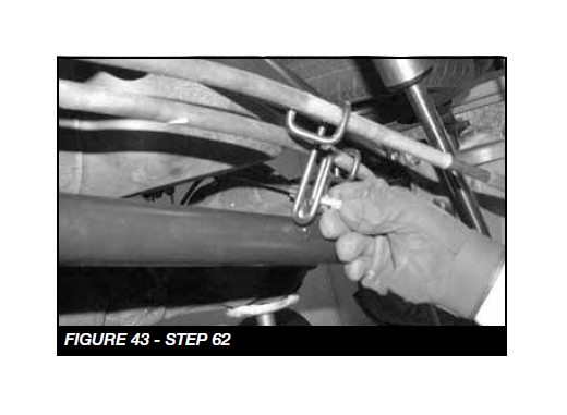
62. Attach the E brake cable to the tab on the link arm using 5/16” hardware. SEE FIGURE 43
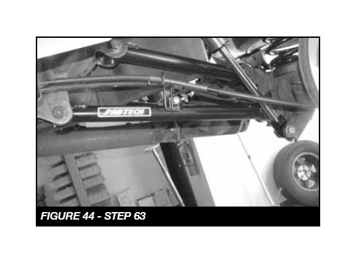
63. Remove the factory upper links arms and discard the links. Save the hardware. Install the new Upper Link Arms into the factory rear axle mounts with the factory hardware. Then attach the arm to the frame mounts also with the factory hardware. Torque to 160 ft.-lbs. SEE FIGURE 44
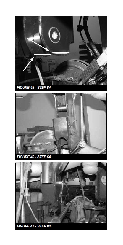
64. Locate FT44187BK Track Bar Bracket, FT44166BK Track Bar Bracket Support, Track bar sleeve FT189 and the ¾”, ½” and 14mm hardware. Cutting of the factory bracket is required. Measure and cut 1/4” off the factory bracket. SEE FIGURE Insert the sleeve into the factory track bar bracket. Position the track bar bracket onto the factory mount on the frame and install the 14mm bolt and hardware. SEE FIGURES 45-47
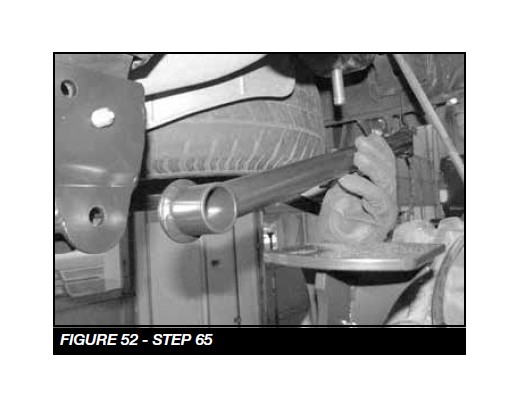
65. Mount the track bar support tube to the rear crossmember using the supplied ¾” x 3” bolt, nut, and washers. Leave loose at this time. SEE FIGURES 52
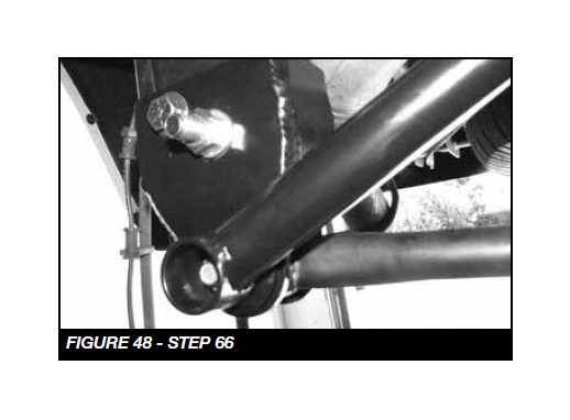
66. Use the open ½” holes in the Fabtech bracket as guide to drill out the two holes for the locking bolts in the factory bracket. Insert the two ½” x 1” bolts into the new holes with nuts tabs FT5036. Torque to 90 ft-lbs. Torque the 14mm bolt in the stock pivot hole to a 160 ft-lbs. Torque the frame side of the trac bar support tube to 317 ft-lbs. SEE FIGURE 48
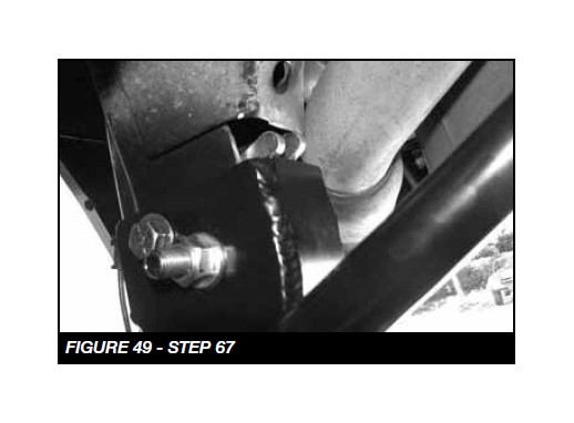
67. Insert the track bar into the Fabtech track bar bracket and install the factory hardware. Torque the factory bolt 160 ft-lbs. SEE FIGURE 49
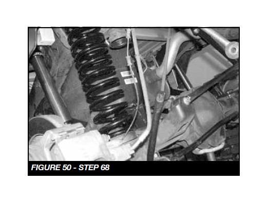
68. Install the Fabtech coil springs FT50302BK using the factory coil isolator. SEE FIGURE 50
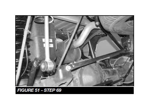
69. Locate the new sway bar links FT1599-2-4 and insert 2 bushing halves and a sleeve into each end (use the supplied lube). Install one end of the link into the frame mount and insert the M12 x 70mm bolt through the sleeve. Attach the sway bar to other end of the link with M12 x 70mm bolt, nut and washer. Torque to 65 ft-lbs. SEE FIGURE 51
70. Install the rear shocks FTS7333 or FTS6333 using the stock hardware. 71. Re-install the rear fender wells.
72. Install tires and wheels and torque lug nuts to wheel manufacturer’s specifications. Turn front tires left to right and check for appropriate tire clearance. Note - Some oversized tires may require trimming of the front bumper & valance.
73. Check front end alignment and set to factory specifications. Readjust headlights.
74. Recheck all bolts for proper torque.
75. Recheck brake hoses, ABS wires and suspension parts for proper tire clearance while turning tires fully left to right.
76. Check the fluid in the front and rear differential and fill if needed with factory specification differential oil. Note - some differentials may expel fluid after filling and driving. This can be normal in resetting the fluid level with the new position of the differential/s.
77. Install Driver Warning Decal. Complete product registration card and mail to Fabtech in order to receive future safety and technical bulletins on this suspension
Vehicles that will receive oversized tires should check ball joints and all steering components every 2500-5000 miles for wear and replace as required.
RE-TORQUE ALL NUTS, BOLTS AND LUGS AFTER 50 MILES AND THEREAFTER UNTIL FASTENERS RETAIN TORQUE SETTING.


