FREE 1 to 3-Day Delivery on Orders $149+ Details
How to Install Barricade I4 Running Boards - Black on your Ram
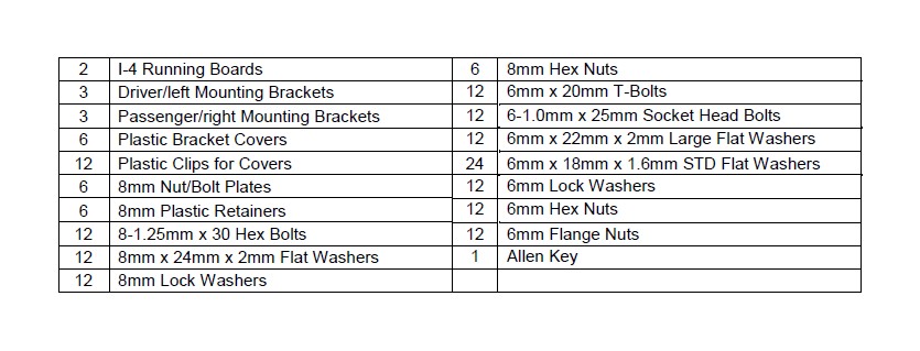
PARTS LIST:
PROCEDURE:
1. REMOVE CONTENTS FROM BOX. VERIFY ALL PARTS ARE PRESENT. READ INSTRUCTIONS CAREFULLY BEFORE STARTING INSTALLATION. DRILLING MAY BE REQUIRED.
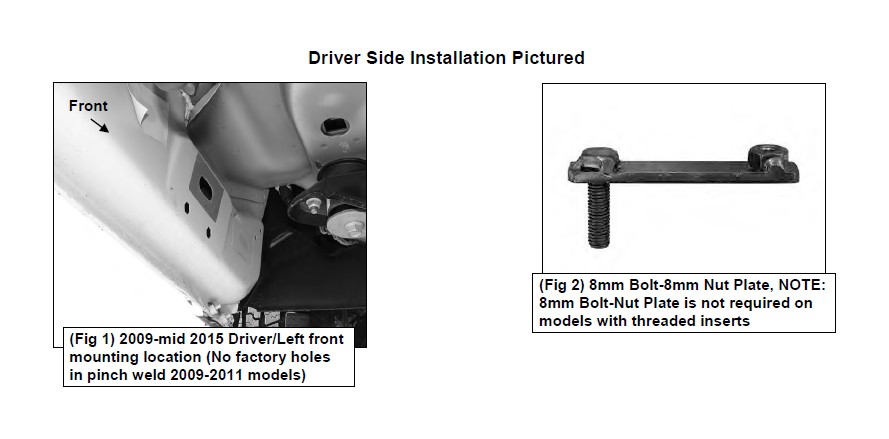
2. Starting at the driver side-front of the vehicle, remove the sealing tape covering the factory holes in the side of the inner panel, (Figure 1).
3. Determine the correct procedure to attach the driver side front Bracket for your model/year:
Models without factory threaded inserts in body panel, (see Figure 1):
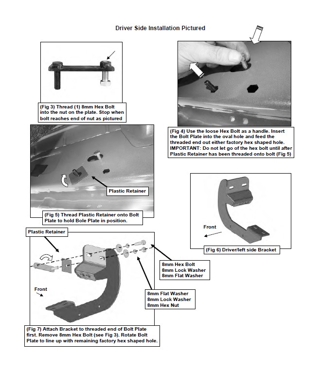
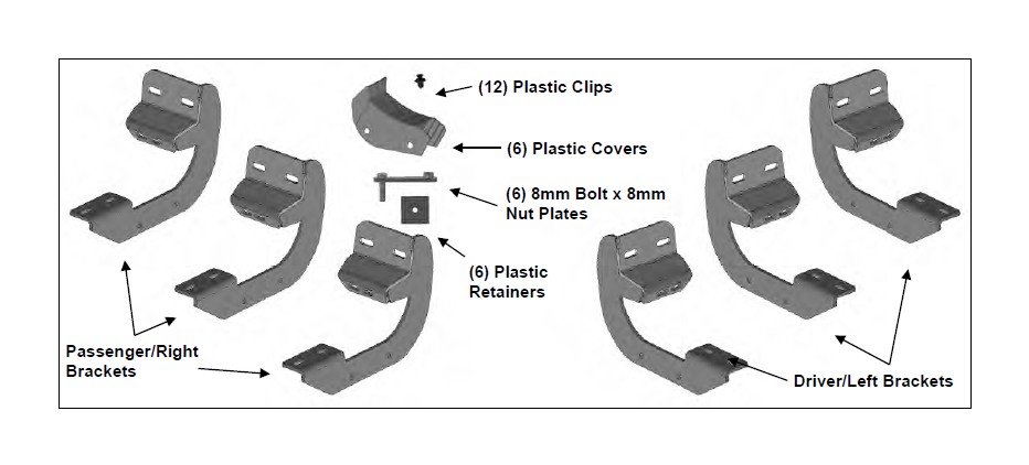
a. Select (1) 8mm Bolt/nut Plate, (Figure 2). Partially thread an 8mm Hex Bolt into the threaded nut on the Nut Plate, (Figure 3). Thread the Hex Bolt in until it is flush with the welded nut. Use the Hex Bolt as a handle and insert the Bolt and Nut Plate into the oval hole, (Figure 4). Feed the threaded bolt on the Bolt Plate through one of the hex shaped factory holes.
b. Thread (1) 8mm Plastic Retainer onto the threaded end and down tight against the body panel, (Figure 5). NOTE: The Plastic Retainer is designed to keep the Bolt/Nut Plate from falling into the body panel and to aid in Bracket installation.
c. Select the driver side front Mounting Bracket, (Figure 6). Attach the Bracket to the threaded end of the Bolt Plate with (1) 8mm Flat Washer, (1) 8mm Lock Washer and (1) 8mm Hex Nut, (Figure 7).
d. Remove the 8mm Hex Bolt from the nut on the Bolt Plate from Step 3a. Rotate the Bolt on the Bolt Plate until the threaded nut lines up with the remaining hole in the Mounting Bracket and hex hole in the body panel, (Figure 7. Attach the Bracket to the threaded Nut Plate with (1) 8mm x 30mm Hex Bolt, (1) 8mm Lock Washer and (1) 8mm Flat Washer, (Figure 7). Do not tighten hardware.
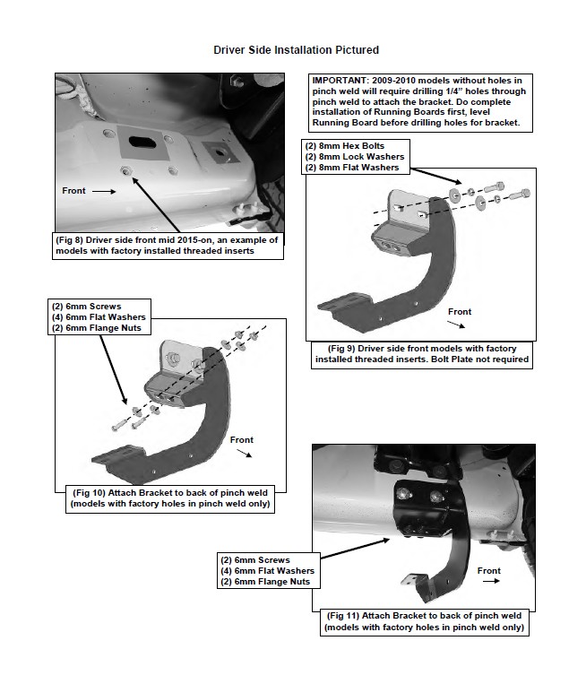
Models with factory threaded inserts, (see Figure 8):
a. Attach the driver side Front Bracket to the threaded inserts with (2) 8mm x 30mm Hex Bolts, (2) 8mm Lock Washers and (2) 8mm Flat Washers, (Figures 8 & 9). Leave hardware loose.
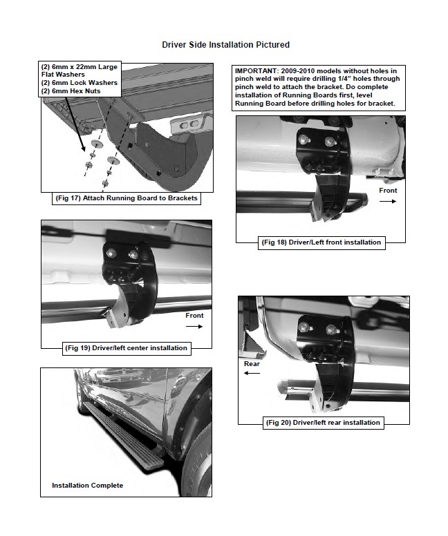
4. Next, attach the Bracket to the back of the pinch weld with (2) 6mm x 25mm Socket Head Screws, (4) 6mm x 18mm STD Flat Washers and (2) 6mm Flange Nuts, (Figures 10 & 11). Do not fully tighten hardware at this time. IMPORTANT: 2009-10 models are not equipped with factory holes and will require drilling through the pinch weld to attach the Bracket. Do not drill through pinch weld at this time, (see Step 11).
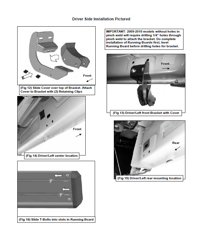
5. Select (1) Plastic Bracket Cover and (2) Retaining Clips. Slide the Cover over the driver side front Bracket. Line up the (2) mounting holes in the Cover with the holes in the Bracket. Insert a Clip into each hole and push center pin to expand Clip, (Figures 12 & 13). Repeat for all Cover installations.
6. Move along the side of the body panel to the center mounting location, (Figure 14). Repeat the appropriate Steps 2-5 to install the driver side center Bracket, (Figure 19).
7. Move to the rear location, (Figure 15). Repeat Step 6 to install the rear Mounting Bracket, (Figure 20).
8. Select (1) Running Board and (6) 6mm T-Bolts. Locate the opening in the end of each channel in the bottom of the Running Board. Slide (3) T-Bolts into each channel, (Figure 16).
9. With assistance, carefully position the Running Board onto the (3) Mounting Brackets. Lift the Running Board up and slide the T-Bolts along the channels to line up with the Brackets. IMPORTANT: Do not slide the Running Board on the Brackets, (front to back or rotate), or the finish on the Running Board may be damaged.
10. Line up the front of the Running Board approximately 2” back, (or locate as desired), from the front wheel opening. Attach the Running Board to the Brackets with (6) 6mm x 22mm Large Flat Washers, (6) 6mm Lock Washers and (6) 6mm Hex Nuts, (Figures 17-20). Do not tighten hardware at this time.
11. Properly level and adjust the Running Board and fully tighten all hardware. 2009-10 models requiring drilling to attach Brackets to pinch weld:
a. Level the Running Board to the vehicle. Make sure all (3) Brackets are tight against the bottom of the body panel and tighten all mounting hardware.
b. Mark the location of the slots onto the pinch weld.
c. Drill (2) 1/4” holes through the pinch weld for each Support Bracket. IMPORTANT: Do not drill too close to the bottom edge of the pinch weld. Drill the holes in the center of the marked slots.
d. Repeat Step 4 to attach the Brackets to the drilled holes in the pinch weld. Check for level then fully tighten all hardware.
12. Move to the passenger side of the vehicle. Remove tape covering front, center and rear locations. Repeat Steps 2-11 for passenger side Mounting Bracket installation.
13. Do periodic inspections to the installation to make sure that all hardware is secure and tight.
To protect your investment, wax this product after installing. Regular waxing is recommended to add a protective layer over the finish. Do not use any type of polish or wax that may contain abrasives that could damage the finish. Mild soap may be used to clean the Running Board.