FREE 1 to 3-Day Delivery on Orders $149+ Details
How to Install Carr Hoop II Steps - Black on your Ram
WARNINGS!
> Do not over tighten the nuts and bolts or damage to the castings and or stripping of the threads could result.
> FOR SAFE AND PROPER USAGE OF THIS PRODUCT, THE MOUNTING INSTRUCTIONS MUST BE FOLLOWED CAREFULLY AND COMPLETELY.
> The manufacturer and distributor of this product are in no way responsible for the consumer’s failure to adhere to the warnings and directions of these instructions in the
event of damage to the consumer’s vehicle, other properties and or personal injury.
MATERIALS NEEDED: Drill Motor, 3/8” drill bit, ¼” drill bit, 1/8” drill bit, pencil, Phillips screw driver, center punch, two ½” wrenches, two 7/16” wrenches and silicone.
MATERIAL FURNISHED: Two step casting, four steel mounting brackets, instruction page and two hardware packs (Important! Not all of the parts in these hardware packs may be needed for proper installation).
1. DIAGRAMS A, B, C, D, E: These steps mount to an extremely strong part of your vehicle, the back side of its rocker panels. For the proper position of the step, the front edge of the seat while in normal driving position should be in line with the center of the step. For personal preference or to avoid any obstruction that may be on the backside of the rocker panel, the step can be moved towards the front or the rear of the vehicle.
2. Assemble the steel mounting brackets to the step as shown in the drawing, but only hand tighten.
3. When positioning the assembled step against the back side of the rocker panel, be sure to avoid all bumps and screws to ensure that the step is against a flat surface. Take a pencil and mark a vertical line that lines up with the front edge of the seat, on the outside painted surface of the pinch weld. (See diagram). Disassemble the brackets from the step.
4. Measure 4 1/8” on each side of the marked vertical line and mark two more lines on that same surface. The dimension between the two outside marked lines should be 8 ¼”.
5. Measure 3/8” from the edge of the pinch weld where you marked the other vertical lines and mark two horizontal lines, creating a cross hair. NOTE: DOUBLE CHECK DIMENSIONS BEFORE DRILLING! (Warning: when drilling holes leave at least 1/8” of metal between the hole and the edge of the pinch weld).
6. Take a center punch and punch the center where the two sets of lines cross.
7. DIAGRAM B: Drill the holes up against the bend of the rocker panel and the pinch weld.
8. Take a 1/8” drill bit and drill out the centered punched holes.
9. Enlarge the 1/8” hole with a 5/16” drill bit.
10. After drilling make sure that all the burrs are removed.
11. Place the steel mounting brackets on the vehicle where the two holes are drilled. DIAGRAM B: Be sure to install the tubes.
12. DIAGRAMS A, D, E: Use the 5/16” x 5/8” hex bolts (DIAGRAM B: uses the 5/16” x 1 ¾” hex bolts) with the 5/16” hex nuts and 5/16” washers to securely tighten the steel mounting brackets on the vehicle. If the 5/16” flat washers do not fit on the pinch weld due to interference don’t use them.
13. DIAGRAM C: Use the 5/16” x 5/8” hex bolts with the 5/16” hex nuts and 5/16” washers and only hand tighten the steel mounting brackets to the vehicle.
14. DIAGRAMS A, B, D, E: Using the top ¼” hole at the top of each steel mounting bracket, take a 1/8” drill bit and drill holes into the body metal. Take the 5/8” long sheet metal screws provided and securely tighten. (Drilling at an angle may be necessary due to interference or for proper alignment). Place the step into the steel mounting brackets and securely tighten. DIAGRAM D ONLY: Ford application will need the front steel mounting bracket to be pivoted back to properly fit.
15. DIAGRAM C: Place the step into the steel mounting brackets and securely tighten. Insert the wedge washers between the back side of the rocker panel and the steel mounting brackets far enough so that the step will be level. While holding the step in the level position, use the top ¼” holes on each steel mounting bracket, mark the holes on both wedge washers. Remove the wedge washers and drill the marked holes out with a ¼” drill bit. Place the wedge washers back into place. Take a 1/8” drill bit and drill through the holes in the steel mounting bracket and the holes in the wedge washer into the body metal. Use the longer sheet metal screws to securely tighten the steel mounting brackets to the vehicle. Remove the step once again from the steel mounting brackets. Now securely tighten the steel mounting brackets to the vehicle. Place the step back into the steel mounting brackets and securely tighten.
16. We advise putting silicone sealer around the areas where the steel mounting brackets comes in contact the body metal.
17. After one month of use, go back and give all hardware a final tightening.
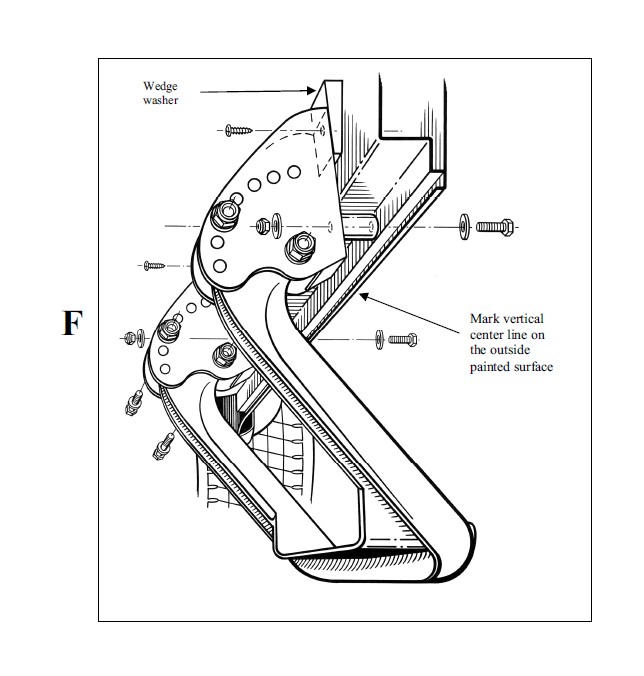
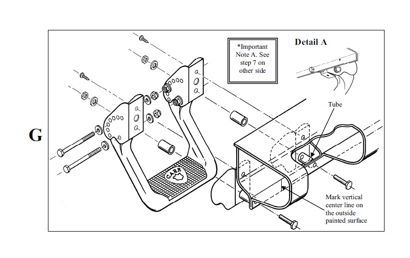
Hoop II Multi-Mount Step Installation InstructionsPart No’s:103991 / 103992 / 103994For Diagrams: F
MATERIALS NEEDED: Drill Motor, 5/16” drill bit, ¼” drill bit, 1/8” drill bit, pencil, Phillips screw driver, center punch, two ½” wrenches, two 7/16” wrenches and silicone.
MATERIAL FURNISHED: Two step casting, four steel mounting brackets, instruction page and two hardware packs (Important! Not all of the parts in these hardware packs may be needed for proper installation).
1. DIAGRAM’S F, G: These steps mount to an extremely strong part of your vehicle, the back side of its rocker panels. For the proper position of the step, the front edge of the seat while in normal driving position should be in line with the center of the step. For personal preference or to avoid any obstruction that may be on the backside of the rocker panel, the step can be moved towards the front or the rear of the vehicle. Diagram G: Be sure to avoid the holes covered with patch material where you will be drilling the top holes later. Also, avoid placing the edge of the steel mounting brackets in the grooved areas of the inner rocker panel.
2. Assemble the steel mounting brackets to the step as shown in the drawing, but only hand tighten.
3. When positioning the assembled step against the back side of the rocker panel, be sure to avoid all bumps and screws to ensure that the step is against a flat surface. Take a pencil and mark a vertical line that lines up with the front edge of the seat, on the outside painted surface of the pinch weld. (See diagram). Disassemble the brackets from the step.
4. Measure 4 1/8” on each side of the marked vertical line and mark two more lines on that same surface. The dimension between the two outside marked lines should be 8 ¼”.
5. Measure 3/8” from the edge of the pinch weld where you marked the other vertical lines and mark two horizontal lines, creating a cross hair. NOTE: DOUBLE CHECK DIMENSIONS BEFORE DRILLING! (Warning: when drilling holes leave at least 1/8” of metal between the hole and the edge of the pinch weld).
6. Take a center punch and punch the center where the two sets of lines cross.
7. *Take a 1/8" drill bit and drill out the centered punched holes. DIAGRAM G SEE DETAIL A: IMPORTANT NOTE A: You must drill the 1/8" hole up against the bend as close as possible. If not, the drill will wander and break through the bottom edge of the pinch weld.
8. Enlarge the 1/8” hole with a 5/16” drill bit.
9. After drilling, make sure that all the burrs are removed.
10. Remove the steel brackets from the step casting.
11. Place the steel brackets back on the vehicle where the two holes were drilled. DIAGRAMS F & G: Be sure to install the tubes.
12. DIAGRAM G: uses the 5/16" x 1 ¾” hex bolts, no washers under head of bolts. DIAGRAM F: uses the 5/16” x 1 ¾” hex bolts using the washers under the head of the bolts) with the 5/16" hex nuts and 5/16" washers to securely tighten the brackets to the vehicle. DIAGRAM F: hand tighten the 5/16” hardware because you will need to move the top of each bracket back to insert the wedge washers in the next step.
13. Place the step back into the steel brackets with the 1/4" hardware provided and securely tighten, making sure that the proper hole selection has been made.
14. DIAGRAMS G: Using the 1/4" holes at the top of each steel mounting bracket, take a 1/8" drill bit and drill holes into the body metal. Drilling at an angle may be necessary due to interference or for proper alignment. Take the 1" sheet metal screws for diagram G and securely tighten. DIAGRAM F: Place the wedge washer at the top of each bracket. Push the wedge washers down far enough to level the step. Hold the wedge washers in place and take a pencil and mark the holes through the ¼” holes in the steel mounting bracket. Take the wedge washers out and drill out the marked holes with a ¼’ drill. Re-install the wedge washers and use the 1” sheet metal screw to securely tighten the bracket and wedge washer against the vehicles body metal.
15. We advise putting silicone sealer around the areas where the zinc plated mounting brackets comes in contact with the body metal.
16. After one month of use, go back and give all hardware a final tightening.