Talk to a Sierra 1500 Sales Tech
1-888-706-1096
M-F 8:30A-11P, Sat-Sun 8:30A-9P
$20K Sweeps! 10 Chances to Win! Enter Daily >

Best Sellers

How to Install Baer Extreme Front Brake Kit - Black (07-18 Sierra 1500) on your GMC Sierra

Installation Time

4 hours

American Muscle
Shop Parts in this Guide
Notices – Read and Follow BEFORE ATTEMPTING INSTALLATION
 All installations require proper safety procedures and protective eyewear.
 All installations assume basic mechanical skill and a factory service manual for the vehicle on which the installation is to be performed.
 All references to the “left” side of the vehicle correlate to the driver’s side of the vehicle.
 Any installation requiring you to remove a wheel or gain access under the vehicle requires use of jack stands appropriate to the weight of the vehicle. In all cases, jack stands rated for a minimum of 2-tons is recommended.
 A selection of hand tools sufficient to engage in the installation of these products is assumed, and is the responsibility of the installer to have in his/her possession prior to beginning this installation. All installations, which require removal of hydraulic hoses and/or bleeding of the brakes, require appropriate fitting/line wrenches, safety catch can, and protective eyewear. Other than these items, if unique or special tools are required they will be stated appropriately in the installation step.
 ALWAYS CONFIRM WHEEL FIT PRIOR TO BEGINNING INSTALLATION OF ANY BRAKE SYSTEM OR “UPSIZED” ROTOR UPGRADE! In addition to checking wheel fitment (available online at www.baer.com), always place the actual corner assembly or a combination of the caliper assembly onto the rotor, and into the actual wheel. This procedure will reconfirm proper clearance between the caliper and the wheel before proceeding with the actual installation.
 Returns will not be accepted for systems that have been partially or completely installed. Use extreme care when checking wheel fitment to prevent any cosmetic damage.

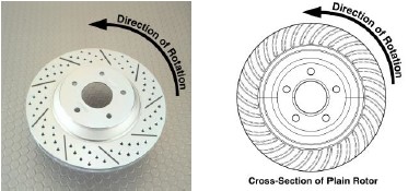
 When installing rotors on any Baer Products be sure to follow the direction of rotation indicated on the rotor hat area with either an arrow, or an “L” for left, or an “R” for right, or both. “L” or left always indicates the driver’s side of US spec vehicles. Images shown are “L” left rotors:


 A proper professional wheel alignment is required for any system requiring replacement of the front spindles, or tie rod ends. Follow factory prescribed procedures and specifications unless otherwise indicated.
 At all times stop the installation if anything is unclear, or the parts require force to install. Consult directly with Baer Technical Staff in such instances to confirm details. Please have these instructions, as well as the part number machined on the component that is proving difficult to install, as well as the make, model, and year (date of vehicle production is preferred) of your vehicle available when you call. Baer’s Tech Staff is available from 8:30-am to 5-pm Mountain Standard Time (Arizona does not observe Daylight Savings Time) at 602 233-1411 Monday through Friday.

INSTALLATION:

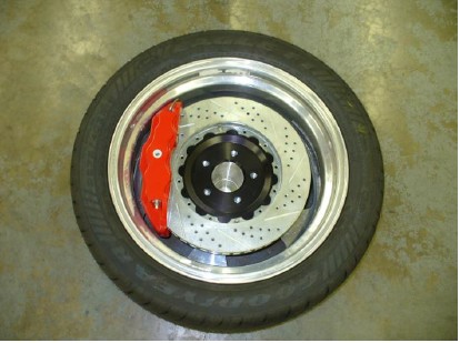
IMPORTANT NOTE: These systems are designed around the Original Equipment spindles with all hardware in place, including debris shield. If aftermarket spindles are used it is imperative to keep the debris shield in place between the spindle and hub as this affects the caliper centering over the rotor. Modifications may be needed to aftermarket spindles and or alternate hardware for installation of a Baer Brake System. Call Baer for assistance.

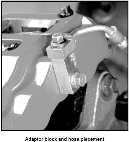
1. Disconnect the fluid hose from the caliper and remove the copper washers from the banjo bolt (these are a one-time use item). New copper washers are provided for the installation.

2. Remove the bolts securing the caliper to the spindle and slide the caliper off of the rotor. Save the bolts as these will be reused.
3. Remove the rotor from the hub and clean both the hub and caliper mounting surfaces to ensure a proper fit for all of the new components.

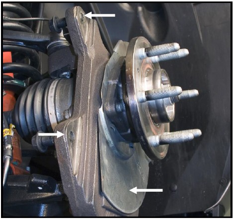
**Note: The photo above shows an aftermarket drop spindle. The upper arrows indicate areas which may require grinding to clear the bracket. The lower arrow shows points to the debris shield which MUST remain in place.

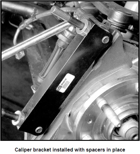
4. Remove the intermediate bracket from the new caliper (installed for ease of shipping). Test fit this to the spindle to check for any interference with the spindle casting.

5. Install the intermediate bracket to the spindle using the original caliper bolts. The flat side of the bracket will face outboard and mount to the outboard side of the spindle. The relief cut into the bracket will face the spindle (inboard side). Check for necessary clearance. Be sure that the 0.400” spacers are in place on the ARP caliper studs. Torque both bolts to 110 ft∙lbs. See photo below for reference:

6. Next, install the correct side rotor and secure with three lug nuts and washers to prevent scratching the hat.
7. With the pads in place, install the correct side caliper (bleeder screws point up) and secure with the 12 point ARP nuts and washers. Torque to 75 ft∙lbs.
8. An adaptor block is provided with your Baer calipers. Using the copper washers (one on each side of the block) and banjo bolt supplied, install this block onto the caliper. Torque to 20 ft∙lbs. See photo below for reference
:**Note: Do not attempt to reuse the copper washers on the banjo bolt of your original fluid hose. The copper washers are a one-time-use-only and will not seal correctly.

9. Using the new copper washers, attach the original hose to the adaptor block on the caliper as seen in the above photo. **IMPORTANT: Position the hose to avoid interference with the wheel and suspension components through the entire range of motion. Torque to 15-20 ft∙lbs.
10. Repeat these steps for the other side and recheck all attachment points and fittings.
Refer to Bleeding, and Pad Bedding & Rotor Seasoning Procedures contained on a separate sheet, or on www.baer.com
For service components and replacement parts contact your Baer Brake Systems Tech Representative.

Best Sellers