FREE 1 to 3-Day Delivery on Orders $149+ Details
How to Install Air Lift Performance SlamAir Adjustable Air Springs for 4-6 in. Drop (02-08 2WD RAM 1500) on your Dodge RAM
Installation Time
2 hours
Tools Required
- Hoist or floor jacks
- Safety stands
- Safety glasses
- Torque wrench
- 5/16” open-end or box wrench
- 7/16” open-end or box wrench
- 9/16” open-end or box wrench
- Crescent wrench
- Ratchet with 9/16”, metric, & 1/2” deep well sockets
- 5/16” drill bit (very sharp)
- Heavy duty drill
- Hose cutter, razor blade, or sharp knife
- Air compressor or compressed air source
- Spray bottle with dish soap/water solution
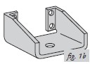
This installation would be typical for a shackle or complete leaf spring replacement for lowering the truck.
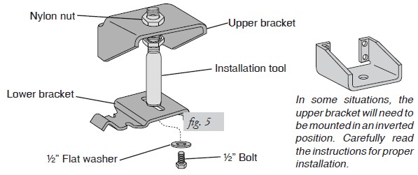
In some situations, the upper bracket will need to be mounted in an inverted position. Carefully read the instructions for proper installation.
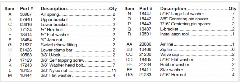
HARDWARE LIST
Installing the SlamAir System
IMPORTANT INSTALLATION INFORMATION
The following is a guide to help you decide how this SlamAir kit will be mounted, depending on how your vehicle was lowered.
This kit typically mounts behind the axle but with some late model applications it can be mounted forward of the axle if needed. The installation tool included with the kit will help check for obstacles and help decide which of the installations discussed is best for the vehicle.
The three types of lowering applications which this kit fit are as follows.
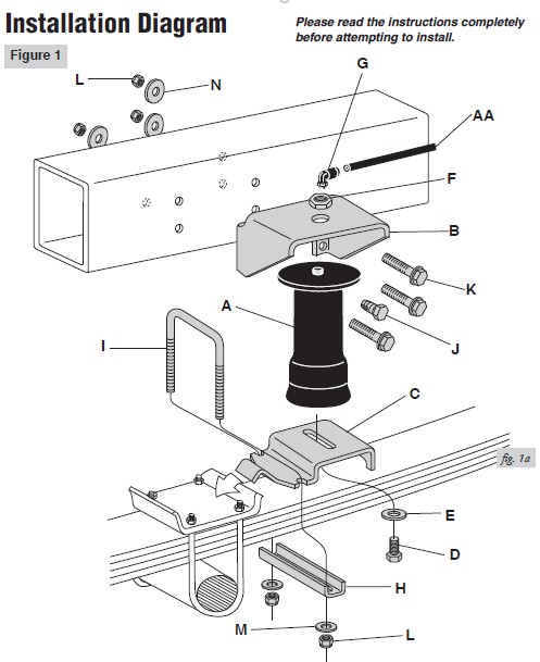
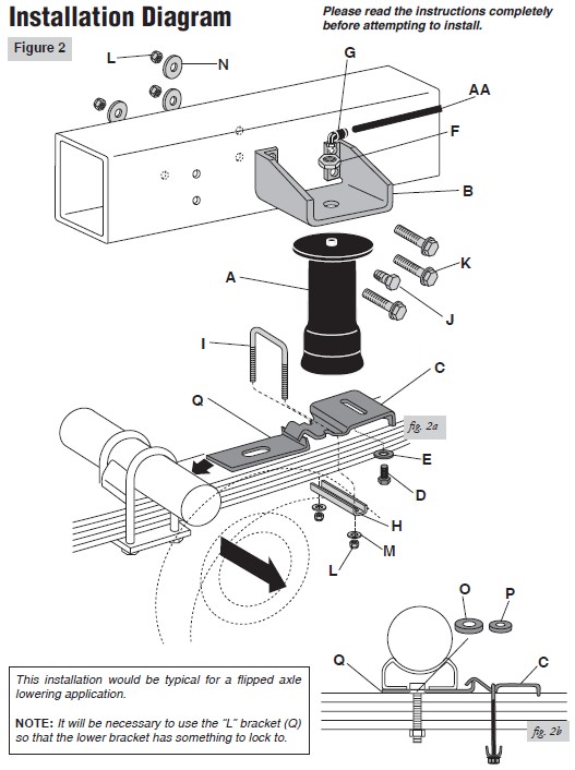
1. Shackle or Leaf Spring Drops: For these applications the air spring assembly can be installed per the figure 1 diagram (pg. 3). You will need to install this kit with the axle at custom ride height, or like it is sitting in the driveway with the tires on. DO NOT install this kit with the axle hanging. Use the installation tool to determine whether the upper bracket will need to be inverted. First try to install the upper and lower bracket like instructed in the Assembling the Installation Tool section (pg. 7) of this manual. If you set the assembly on the leaf spring and the upper bracket cannot be properly aligned on the middle section of the frame rail, it may be necessary to invert the upper bracket (fig. 1b).
2. Flipped Axle Drops: For these applications you will install the air spring assembly as instructed in the figure 2 diagram (pg. 4). For this application, it will be necessary to install an “L” bracket between the leaf spring and the axle. The bracket provides a lock for the lower bracket to attach, preventing the lower bracket from moving down the leaf spring and causing misalignment. For most of these types of installations it will be necessary to invert the upper bracket (fig. 1b) in order to install the assembly.
3. Lowering Kits Using Notched Frames: This kit does not fit these types of installations without modifications being made to the kit. You may need to modify or even weld the kit depending on how the upper bracket lines up with the c-notch.
NOTE: On some models or applications it may be necessary to invert the upper bracket in a “legs up” position to achieve the correct mounting height. Do not hang the axle on a frame contact hoist while checking for proper placement of the upper bracket. The vehicle must be in the custom ride height condition—how the vehicle would sit in the driveway or parking lot.
GETTING STARTED
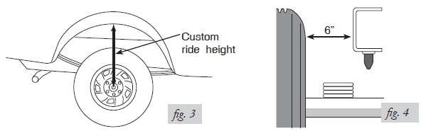
1. Determine the custom ride height of the lowered vehicle. The custom ride height is the distance between the bottom edge of the wheel-well and the center of the hub when the vehicle is in the custom, lowered condition (fig. 3). In some cases, the ride height is not perfectly level.
a. Remove unusual loads and examine the vehicle from the side to ensure it is on a level surface.
b. If necessary—in cases where your leaf springs are sagging badly—use a jack to raise the rear end so that the vehicle achieves the custom, lowered ride height.
2. Measure the distance between the frame and the tire. This kit requires a minimum of 6” of clearance for a fully inflated air spring (fig. 4).
RAISING THE VEHICLE
1. Raise the vehicle and remove the wheels.
2. Ensure that the vehicle is at the custom, lowered ride height. If not, raise the frame or lower the axle as necessary.
a. If the vehicle is raised with an axle contact hoist, place axle stands under the frame and lower the axle as needed.
b. If the vehicle is raised with a frame contact hoist, place axle stands under the axle and lower the frame as needed.
c. If the vehicle is raised with a jack and supported with axle stands on the frame, use a floor jack to lower the axle.
ASSEMBLING THE INSTALLATION TOOL
1. The tool provided with this kit will assist in proper setup and alignment of the air spring and will also position the upper bracket for drilling the bolt holes. The tool attaches to the upper and lower bracket and is rigid so that it will self-align the upper bracket. The threaded section of the upper part of the tool ensures that the air spring can only be mounted at the correct height. This kit is intended to be mounted behind the axle.
2. Secure the upper bracket to the installation tool using the provided nylon nut (fig. 5).
NOTE: As stated in the Important Information section, it may be necessary to invert the upper bracket based on the type of drop installed.
3. Loosely attach the tool to the lower bracket using a ½” flat washer and a ½” bolt (fig. 5). Leave loose for later adjustment.
INSTALLING THE L-BRACKETS (For flipped axle lowered applications)
1. Support the frame and drop the rear axle all the way until the axle is hanging. If the shock stops the axle from hanging, remove the lower shock bolts.
2. Remove the leaf spring retaining u-bolts on one side and, with a floor jack, raise the axle to clear the leaf spring centering pin.
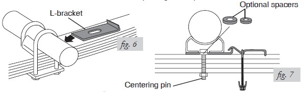
3. A spacer is provided to accommodate the increased thickness caused by the lower bracket. Clamp the leaf spring together with a c-clamp so the leaf center pin can be removed. Remove the centering pin and install one spacer, per pin (see fig. 7).
NOTE: There are two different size spacers. Use the pin that fits and discard the other.
4. Reinstall the centering pin. If the nut does not have full thread contact, replace the centering pin.
5. Set the lower L-bracket on the leaf, making sure the centering pin goes through the slot on the L-bracket. Drop the axle down, and reinstall the u-bolts. Slightly tighten the u-bolts so that the lower bracket can be adjusted later (fig. 6).
NOTE: It is recommended that the u-bolts be replaced with new ones (not provided).
6. Install the L-bracket on the other side, repeating the steps above.
ATTACHING THE LOWER BRACKET
1. Set the assembly on the leaf spring behind the axle.
NOTE: On some late model applications the assembly can be mounted forward of the axle if needed.
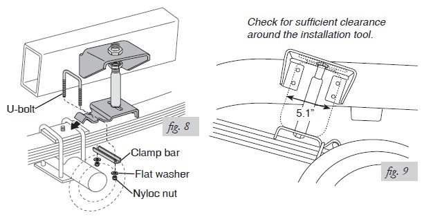
2. Depending on how the vehicle was dropped, with the hook end of the lower bracket placed over the edge of the spring retaining plate, secure the lower bracket to the leaf spring using the provided u-bolt, clamp bar, flat washers and nyloc nuts (fig. 8). Torque to 16 ft/lbs. If the vehicle was dropped by flipping the axle, attach the lower bracket over the L-bracket as noted in fig. 2 or fig. 7.
NOTE: The bracket will pull down flat to the leaf spring when the nyloc nuts are tightened.
3. The air spring will expand to 5.1” in diameter at maximum inflation pressure. Check horizontally along the shaft of the installation tool for sufficient clearance of 2.5” around the tool (fig. 9).
POSITIONING THE UPPER BRACKET
NOTE: At this point you should have determined how the upper bracket needs to be positioned, (legs down or inverted with legs up). Also, it should be determined where the assembly will be mounted, depending on the drop used and whether the L-bracket was installed.
1. Using the slot in the lower bracket, push the upper bracket against the frame rail.
2. Use the two nylon nuts on the threaded portion of the installation tool to adjust the upper bracket so that the upper bracket legs are flat against the frame rail and all four holes are in the middle section of the frame. The mounting holes must not fall on the rounded edges of the frame rail and AT LEAST 1.5” must be left above the top of the upper bracket for air fitting clearance.
ATTACHING THE UPPER BRACKET
IMPORTANT: Please read this entire section before drilling any holes.
BEFORE DRILLING, CHECK THE BACK SIDE OF THE FRAME FOR CLEARANCE ISSUES SUCH AS BRAKE LINES, GAS LINES, ELECTRICAL LINES, ETC. ALL OBSTACLES NEED TO BE TEMPORARILY RELOCATED TO CLEAR THE AREA.
Driver-side installation
NOTE: On the driver-side installation there is a wiring loom on the inside frame rail, behind the axle. This is why a self tapping screw is used to install the upper bracket. Please keep in mind that if the upper bracket is installed in alocation different than the normal stock mounting, this may alter where this hole lines up. Adjust and attach the upper bracket accordingly.
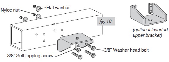
1. Center punch the lower rear hole and drill a 3/8” hole through the frame.
2. Loosely install a 3/8” washer head bolt, a large flat washer, and a nyloc nut (fig. 10).
3. Center punch the forward lower hole and drill a 3/8” hole through the frame.
4. Remove the installation tool by removing the bolt securing it to the lower bracket. Swing the bracket up and remove the nylon nut on the top of the upper bracket. Remove the installation tool and save the hardware for later air spring mounting.
5. Move the upper bracket back to the mounting location and secure at the forward, lower mounting hole using a 3/8” washer head bolt, large flat washer and nyloc nut (fig. 10).
6. Center punch and drill a 5/16” hole for the forward upper hold and install a 3/8” self tapping screw (fig. 10). Tighten to 16 ft/lbs.
7. Drill the remaining hole out to a 3/8” diameter and install a 3/8” washer head bolt, large flat washer and nyloc nut.
Passenger-side installation
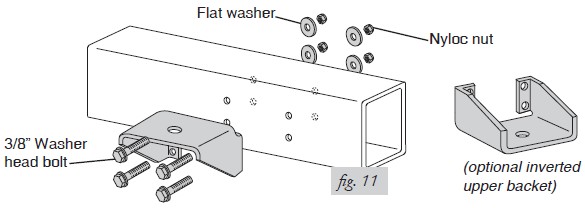
1. Install the passenger-side assembly in the same manner as above, except the forward upper hole location. Drill this hole to a 3/8” diameter and install a 3/8” washer head bolt, large flat washer, and a nyloc nut. No self-tappeing screw is used on the passenger side (fig. 11).
INSTALLING THE AIR SPRING
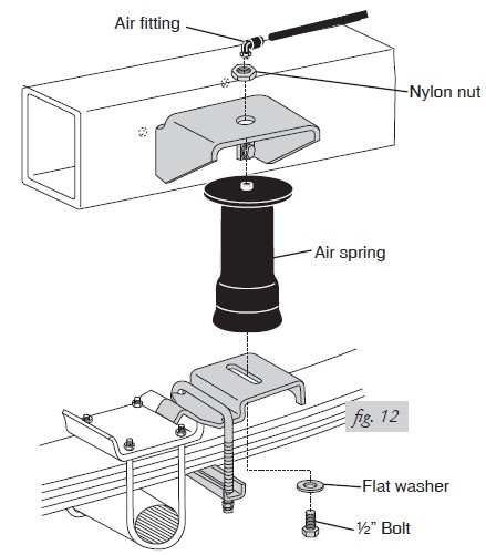
1. Install the 90˚ swivel air fitting to the top of the air spring (fig.12). Use a 7/16” open end wrench to tighten on the metal hex nut only. Tighten 1½ turns. Do not overtighten.
NOTE: This swivel air fitting is precoated with a sealant.
2. Guide the fitting through the center mounting hole in the upper bracket (see fig. 1 and fig. 12).
3. Attach the air spring to the lower bracket using a flat washer and bolt. Carefully hand turn the air spring onto the lower mounting bolt. Leave loose for later adjustment (fig. 12)
4. Loosely install a nylon nut over the air fitting and onto the upper threadpost of the air spring (see fig. 1 and fig. 12).
ALIGNING THE AIR SPRING
IMPORTANT: With the top and bottom of the air spring still loose, inflate the air spring to approximately 10 PSI.
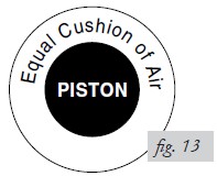
1. Use the slotted adjustment in the lower bracket to correctly align the air spring between the upper and lower brackets. This can be accomplished by lightly tapping it inboard (towards the vehicle) or outboard (towards the wheel) for proper alignment. There should be a symmetrical cushion of air around the base of the air spring when correctly positioned (fig. 13).
2. Tighten the lower mounting bolt with a ¾” wrench. Hand tight is sufficient. Do not attempt to hold the air spring with any type of tool.
3. Tighten the nylon nut to 4 ft/lbs.
4. If the L-brackets were installed (flipped application installation), retorque the u-bolts to OEM specifications.
5. Repeat on the other side of the vehicle.
INSTALLING THE AIR LINES
1. Choose a convenient location for mounting the inflation valves. Popular locations for the inflation valve are:
a. The wheel well flanges.
b. License plate recess in bumper.
c. Under the gas cap access door.
d. Through license plate itself.
NOTE: What ever the chosen location is, make sure there is enough clearance around the inflation valves for an air chuck.
2. Drill a 5/16” hole to install the inflation valves.
3. Cut the air line assembly in two equal lengths.
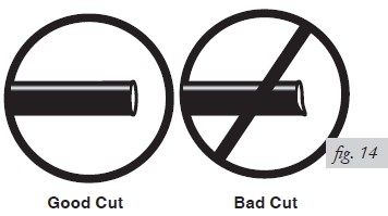
CAUTION: WHEN CUTTING OR TRIMMING THE AIR LINE, USE A HOSE CUTTER, A RAZOR BLADE OR A SHARP KNIFE. A CLEAN, SQUARE CUT WILL PREVENT LEAKS. DO NOT USE WIRE CUTTERS OR SCISSORS TO CUT THE AIR LINE. THESE TOOLS MAY FLATTEN OR CRIMP THE AIR LINE, CAUSING IT TO LEAK AROUND THE O-RING SEAL INSIDE THE ELBOW FITTING (FIG. 14).
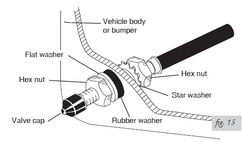
4. Place a 5/16” nut and a star washer on the air valve. Leave enough of the inflation valve in front of the nut to extend through the hole and have room for the rubber washer, flat washer, and 5/16” nut and cap. There should be enough valve exposed after installation - approximately ½” - to easily apply a pressure gauge or an air chuck (fig. 15).
5. Push the inflation valve through the hole and use the rubber washer, flat washer, and another 5/16” nut. Tighten the nuts to secure the assembly in place (fig. 15).
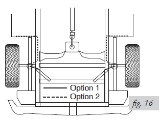
6. Route the air line along the frame to the air fitting on the air spring (fig. 16). Keep AT LEAST 6” of clearance between the air line and heat sources, such as the exhaust pipes, muffler, or catalytic converter. Avoid sharp bends and edges. Use the plastic tie straps to secure the air line to fixed, non-moving points along the chassis. Be sure that the tie straps are tight, but do not pinch the air line. Leave at least 2” of slack to allow for any movement that might pull on the air line.
7. Cut off air line leaving approximately 12” of extra air line. A clean square cut will ensure against leaks (see fig. 14). Insert the air line into the air fitting. This is a push to connect fitting. Simply push the air line into the 90° swivel fitting until it bottoms out (9/16” of air line should be in the fitting).
CHECKING FOR LEAKS
1. Inflate the air spring to 30 PSI and spray all connections and the inflation valves with a solution of 1/5 liquid dish soap and 4/5 water to check for leaks. Spot leaks easily by looking for bubbles in the soapy water.
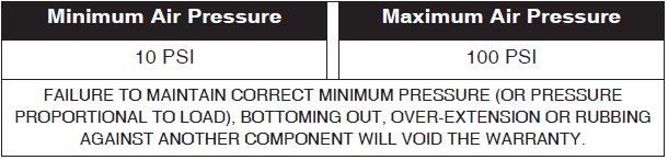
2. After the test, deflate the springs to the minimum pressure required to restore the custom ride height, no less than 10 PSI.
3. Check the air pressure again after 24 hours. A 2-4 PSI loss after initial installation is normal. Retest for leaks if the loss is more than 10 lbs.
FIXING LEAKS
1. If there is a problem with the swivel fitting:
a. Check the air line connection by deflating the spring and removing the line by pulling the collar against the fitting and pulling firmly on the air line. Trim 1” off the end of the air line. Be sure the cut is clean and square (see fig. 14). Reinsert the air line into the push-to-connect fitting.
b. Check the threaded connection by tightening the swivel fitting another ½ turn. If it still leaks, deflate the air spring, remove the fitting, and re-coat the threads with thread sealant. Reinstall by hand tightening as much as possible, then use a wrench for an additional two turns.
2. If there is a problem with the inflation valve, then:
a. Check the valve core by tightening it with a valve core tool.
b. Check the air line connection by removing the air line from the barbed type fitting.
DO NOT CUT THE AIR LINE COMPLETELY OFF AS THIS WILL NICK THE BARB AND RENDER THE FITTING USELESS.
3. If the preceding steps have not resolved the problem, call Air Lift customer service at (800) 248-0892 for assistance.
Before Operating
INSTALLATION CHECKLIST
Clearance test — Inflate the air springs to 60 PSI and make sure there is at least ½”
clearance from anything that might rub against each sleeve. Be sure to check the tire,
brake drum, frame, shock absorbers and brake cables.
Leak test before road test — Inflate the air springs to 60 PSI and check all connections for leaks. Refer to Checking for Leaks on page 12. All leaks must be eliminated before the vehicle is road tested.
Heat test — Be sure there is sufficient clearance from heat sources, at least 6” for air springs and air lines. If a heat shield was included in the kit, install it. If there is no heat shield, but one is required, call Air Lift customer service at (800) 248-0892.
Fastener test — Recheck all bolts for proper torque.
3/8” Frame bolts ...................16 ft/lbs
U-bolt lock nuts ....................16 ft/lbs
Stock U-bolts (if removed)....Use OEM recommended stock torque specifications
Road test — The vehicle should be road tested after the preceding tests. Inflate the
springs to 25 PSI (50 PSI if the vehicle is loaded). Drive the vehicle 10 miles and recheck for clearance, loose fasteners and air leaks.
Operating instructions — If professionally installed, the installer should review the
operating instructions with the owner. Be sure to provide the owner with all of the
paperwork that came with the kit.
POST-INSTALLATION CHECKLIST
Overnight leak down test — Recheck air pressure after the vehicle has been used for 24 hours. If the pressure has dropped more than 5 PSI, then there is a leak that must be fixed. Either fix the leak yourself or return to the installer for service.
Air pressure requirements: I understand the air pressure requirements of my air spring system. Regardless of load, the air pressure should always be adjusted to maintain ride height at all times.
Thirty day or 500 mile test: I understand that I must recheck the air spring system after 30 days or 500 miles, whichever comes first. If any part shows signs of rubbing or abrasion, the source should be identified and moved, if possible. If it is not possible to relocate the cause of the abrasion, the air spring may need to be remounted. If professionally installed, the installer should be consulted. Check all fasteners for tightness.
Maintenance and Servicing
MAINTENANCE GUIDELINES
NOTE: By following these steps, vehicle owners will obtain the longest life and best results from their air spring.
1. Check the air pressure weekly.
2. Always maintain the custom ride height. Never inflate beyond 100 PSI.
3. If you develop an air leak in the system, use a soapy water solution to check all air line connections and the inflation valve core, before deflating and removing the spring.
4. When increasing load, always adjust the air pressure to maintain custom ride height. Increase or decrease pressure from the system as necessary to attain the custom ride height for optimal ride and handling. Remember that loads carried behind the axle (including tongue loads) require more leveling force (pressure) than those carried directly over the axle.
CAUTION: FOR YOUR SAFETY AND TO PREVENT DAMAGE TO YOUR VEHICLE, DO NOT ExCEED MAxIMUM GROSS VEHICLE WEIGHT RATING (GVWR), AS INDICATED BY THE VEHICLE MANUFACTURER. ALTHOUGH YOUR AIR SPRINGS ARE RATED AT A MAxIMUM INFLATION PRESSURE OF 100 PSI, THE AIR PRESSURE ACTUALLY NEEDED IS DEPENDENT ON YOUR LOAD AND GVWR.
5. Always add air to the springs in small quantities, checking the pressure frequently. Sleeves require less air volume than a tire and inflate quickly.
6. Should it become necessary to raise the vehicle by the frame, make sure the system is at a minimum pressure (10 PSI) to reduce tension on the suspension/brake components. Use of on-board leveling systems do not require deflation or disconnection.
TUNING THE AIR PRESSURE
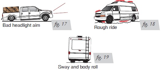
Pressure determination comes down to three things — level vehicle, ride comfort, and stability.
1. Level vehicle
If the vehicle’s headlights are shining into the trees or the vehicle is leaning to one side, then it is not level (fig. 17). Raise the air pressure to correct either of these problems and level the vehicle.
2. Ride comfort
If the vehicle has a rough and harsh ride it may be due to either too much pressure or not enough (fig. 18). Try different pressures to determine the best ride comfort.
3. Stability
Stability translates into safety and should be the priority, meaning the driver may need to sacrifice a perfectly level and comfortable ride. Stability issues include roll control, bounce, dive during braking and sponginess (fig. 19). Tuning out these problems usually requires an increase in pressure.
GUIDELINES FOR ADDING AIR
1. Start with the vehicle level or slightly above.
2. When in doubt, always add air.
3. For motorhomes, start with 50-100 PSI in the rear because it can be safely assumed that it is heavily loaded.
4. If the front of the vehicle dives while braking, increase the pressure in the front air bags, if equipped.
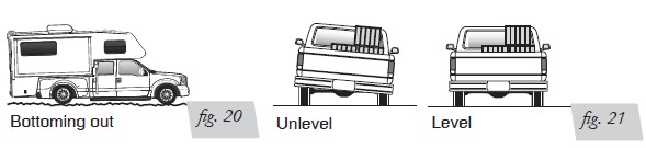
5. If it is ever suspected that the air bags have bottomed out, increase the pressure (fig. 20).
6. Adjust the pressure up and down to find the best ride.
7. If the vehicle rocks and rolls, adjust the air pressure to reduce movement.
8. It may be necessary to maintain different pressures on each side of the vehicle. Loads such as water, fuel, and appliances will cause the vehicle to be heavier on one side (fig. 21). As much as a 50 PSI difference is not uncommon.