FREE 1 to 3-Day Delivery on Orders $149+ Details
How to Install Air Lift Performance LoadLifter 5000 (09-18 RAM 1500) on your Dodge RAM
Installation Time
2 hours
Tools Required
- Standard and metric open-end or box wrenches
- Adjustable wrench
- Ratchet.
- Standard and metric, regular and deep-well sockets
- 1/4” and 5/16” drill bits (very sharp)
- Heavy-duty drill
- Torque wrench
- 4” Grinder or metal cutting tool
- Standard and metric hex-key wrenches
- Hose cutter, razor blade, or sharp knife
- Hoist or floor jacks
- Safety stands
- Safety glasses
- Black paint or undercoating
- Air compressor or compressed air source
- Spray bottle with dish soap/water solution

Shop Parts in this Guide
IDENTIFYING THE DIFFERENCES BETWEEN KITS
Should you need to contact Air Lift customer service, you will need to know which kit you are inquiring about: standard LoadLifter 5000, LoadLifter 5000 Ultimate or LoadLifter 5000 Ultimate Plus. The kits are easily identifiable by looking at the roll plates and air lines.
Standard LoadLifter 5000 — Zinc-plated steel roll plates and black nylon air lines.
LoadLifter 5000 Ultimate — Black powder-coated roll plates and black nylon air lines.
LoadLifter 5000 Ultimate Plus — Stainless steel roll plates, braided stainless steel air lines, stainless steel air spring mounting hardware.
Air Lift offers two Ultimate Plus upgrade kits:
52300 - Braided stainless steel air line and fittings.
52301 - Stainless steel roll plates, air spring mounting hardware, braided stainless steel air lines and fittings.

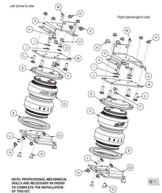
Installation Diagram
Introduction
The purpose of this publication is to assist with the installation, maintenance and troubleshooting of the standard LoadLifter 5000, LoadLifter 5000 Ultimate or LoadLifter 5000 Ultimate Plus air spring kits. All LoadLifter 5000 Series kits utilize sturdy, reinforced, commercial-grade single or double, depending on the kit, convolute bellows. LoadLifter 5000 Ultimate kits add an internal jounce bumper and black powder-coated roll plates. LoadLifter 5000 Ultimate Plus kits also have an internal jounce bumper, but add stainless steel roll plates, air lines and air spring mounting hardware.
The air springs are manufactured like a tire with layers of rubber and cords that control growth. LoadLifter 5000 series kits are recommended for most 3/4- and 1-ton pickups and SUVs with leaf springs and provide up to 5,000 pounds of load-leveling support with air adjustability from 5-100 PSI (.34-6.9BAR).
It is important to read and understand the entire installation guide before beginning installation or performing any maintenance, service or repair.
Air Lift Company reserves the right to make changes and improvements to its products and publications at any time. For the latest version of this manual, contact Air Lift Company at (800) 248-0892 or visit airliftcompany.com.
IMPORTANT SAFETY NOTICE
The installation of this kit does not alter the gross vehicle weight rating (GVWR) or payload of the vehicle. Check the vehicle’s owner’s manual and do not exceed the maximum load listed for this vehicle.
Gross vehicle weight rating: The maximum allowable weight of the fully loaded vehicle (including passengers and cargo). This number - along with other weight limits, as well as tire, rim size and inflation pressure data - is shown on the vehicle’s Safety Compliance Certification Label.
Payload: The combined, maximum allowable weight of cargo and passengers that the truck is designed to carry. Payload is GVWR minus the base curb weight.
NOTATION EXPLANATION
Hazard notations appear in various locations in this publication. Information which is highlighted by one of these notations must be observed to help minimize risk of personal injury or possible improper installation which may render the vehicle unsafe. Notes are used to help emphasize areas of procedural importance and provide helpful suggestions. The following definitions explain the use of these notations as they appear throughout this guide.
DANGER: INDICATES IMMEDIATE HAZARDS WHICH WILL RESULT IN SEVERE PERSONAL INJURY OR DEATH.
WARNING: INDICATES HAZARDS OR UNSAFE PRACTICES WHICH COULD RESULT IN SEVERE PERSONAL INJURY OR DEATH.
CAUTION: INDICATES HAZARDS OR UNSAFE PRACTICES WHICH COULD RESULT IN DAMAGE TO THE MACHINE OR MINOR PERSONAL INJURY.
Installing the LoadLifter 5000 Series System
GETTING STARTED
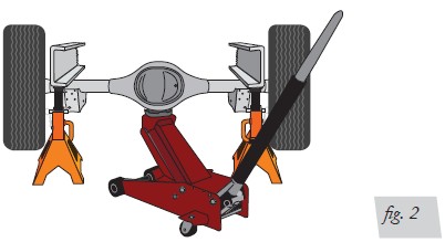
In order to install the upper frame brackets (A), it will be necessary to remove the coil springs as follows:
1. Lift the vehicle up and support the frame with jack stands. Leave enough room to drop the axle down low enough to remove the coil springs (Fig. 2). Remove the rear wheels.
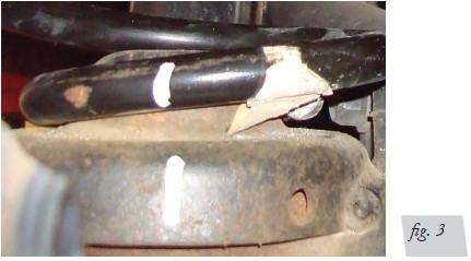
2. Mark the bottom of the right-hand and left-hand coil springs and lower spring seat
mounts with chalk or a paint marker to make sure the spring is put back the same
way it is removed (Fig. 3).
3. Remove both lower shock bolts and slowly lower the axle until the springs can be
removed.
NOTE: Lower the axle carefully and avoid putting stress on the f lexible brake lines.
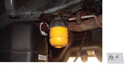
4. Remove both jounce bumpers from both sides (Fig. 4).
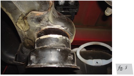
5. Grind the welds off the jounce bumper cups that attach them to the jounce bumper
frame bracket (Fig. 5). Remove and discard from both sides of the vehicle.
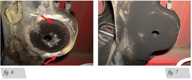
Grind the remaining welds flush to the frame (Fig. 6). Spray the frame with paint or undercoating to cover the bare surface after grinding (Fig. 7).
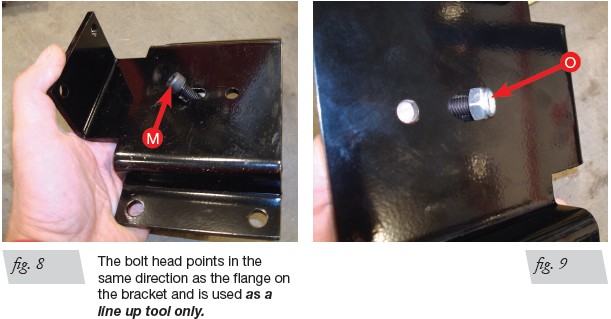
Install the socket head M8 bolt (M) into the frame bracket (A) slot closest to the flange on the bracket (Fig. 8). Cap with the nylon lock nut (O) as shown (Fig. 9).
NOTE: The M8 bolt is used as a tool to ensure the upper bracket is aligned properly.
8. Thread the nylon lock nut on the M8 bolt only enough to allow the bolt to slide freely
in the slot. This will allow you to align the frame bracket correctly.
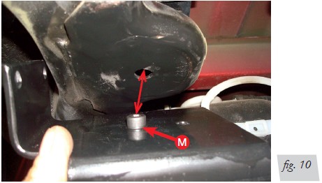
9. Set the frame bracket (with the socket head bolt in it), on the frame, with the flange
pointing up. Insert the socket head bolt line up tool into the existing hole in the frame
that was under the stock jounce bumper (Fig. 10).
10. The bracket should sit flush to the bottom of the frame. If there is any leftover weld
holding the bracket off the frame, remove and grind down so the bracket is flush.
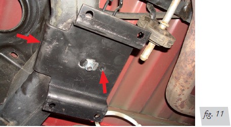
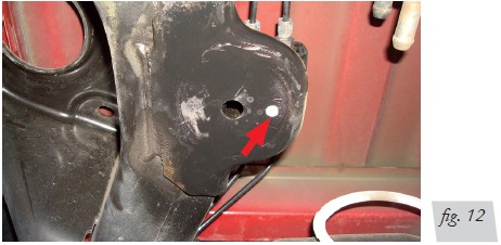
11. With the socket head bolt in the hole, push the flange against the side of the frame
(Fig. 11) and mark the existing hole under the frame with a paint marker (Fig. 12).
NOTE: The socket head bolt remains in place but requires no additional tightening.
NOTE: If possible, with the bracket in position, use a 21/64” (or closest) centering punch to fit into the hole and center-punch the frame for an exact center of the hole.
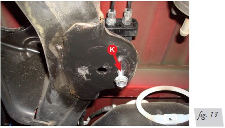
12. Center-punch the frame and drill a 1/4” hole (Fig. 13). Start a 5/16” self-tapping
screw (K) into the hole, making sure it is straight, and tighten it enough to form
the threads needed to set the screw (Fig. 13). Remove the screw once threads are
formed.
13. Set the bracket back in place on the frame and bolt into position using the
self-tapping screw previously set into the frame. Tighten the screw making sure
the washer head portion of the screw is flat to the bracket, and torque to 15 lb.-ft.
(20Nm).
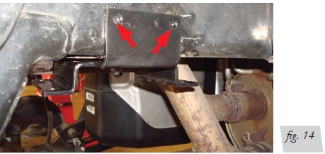
14. Make sure the bracket is flat to the bottom of the frame, center punch and drill
through the frame with a 1/4” bit using the holes in the side of the flange as a guide
(Fig. 14).
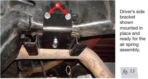
15. Install two more self-tapping screws (K) in the side, making sure the flat head portion
of the bolt is flush to the bracket, and torque to 15 lb.-ft. (20Nm) (Fig. 15). Repeat for
the other side.
16. Once the frame brackets have been installed on both sides, the stock suspension
can be put back together.
17. Set the coil springs back into position using the index marks from the previous step
and raise the axle back up making sure the spring indexes into the top and bottom
spring seats correctly.
18. Reinstall the wheels and lower the vehicle so the wheels rest on the ground. Torque
the lug nuts to the manufacturer’s torque specs.
19. Install the lower shock bolts back onto the axle and torque to 100 lb.-ft. (135Nm).
ASSEMBLING THE AIR SPRINGS
1. Set a roll plate (E) onto the air spring (D).
NOTE: The radius (rounded) edge of the roll plate (E) will be toward the air spring, so that the air spring is seated inside both roll plates.
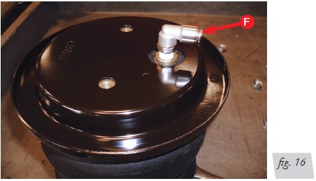
2. Install the swivel fitting (F) into the top of the air spring finger tight plus 1 1/2 turns
(Fig. 16).
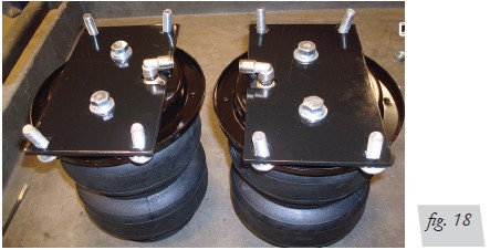
3. Insert four carriage bolts (L) into the upper air spring bracket (B) and set the upper
bracket onto the air spring assembly (Fig. 17).
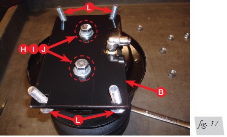
4. Attach the upper air spring bracket using two 3/8” hex-head bolts (H), two lock
washers (I) and two flat washers (J). Torque to no more than 20 lb.-ft. (27Nm) Repeat
for the opposite side. Figure 18 shows both upper assemblies.
5. Flip the air spring assemblies upside down and set a roll plate (E) over the air spring
(same as in step one).
6. Position the air spring assemblies so that the fittings are outboard and away from
each other (Fig. 19).
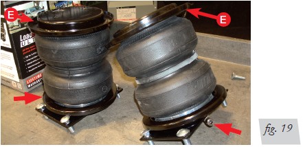
NOTE: The finished assemblies will be left and right-hand specific, and the fittings that are on the top of the air springs should be facing the outside (tire side) of the vehicle once into position.
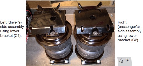
7. Set the left lower bracket (C1) onto the left side assembly and attach with two 3/8” flat-head screws (G). Assemble the other air spring using the right-side lower bracket (C2). Torque to no more than 20 lb.-ft. (27Nm) (Fig. 19). Figure 20 shows the completed assemblies.
INSTALLING THE ASSEMBLIES
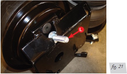
1. Index a 3/8” carriage bolt (L) into the opening on the front of the driver’s side assembly as shown (Fig. 21).
2. Drop the axle again to gain clearance to put the two assemblies into position on the
axle.
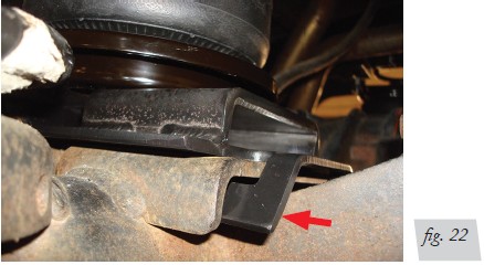
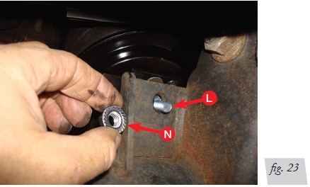
3. Set the left (driver’s) side assembly into position with the carriage bolt still in the slot
(previously installed). Set into place on the axle, making sure the back of the bracket
is “hooked” below the jounce bumper strike plate. Push the assembly forward while
lining up the carriage bolt with the existing hole in the front of the lower jounce
bumper strike plate (Figs. 22 & 23). Cap the carriage bolt with a 3/8” serrated lock
nut (N), but leave loose at this time.
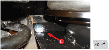
4. Insert another 3/8” carriage bolt (L) through the remaining hole in the front side of
the bracket (Fig. 24).
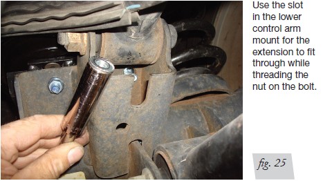
5. It will be necessary to use a socket with an extension to reach the inside threads on
the carriage bolt previously set into position (Fig. 25). It may be helpful to pull the
carriage bolt out slightly so that it can be angled enough to get started on the thread.
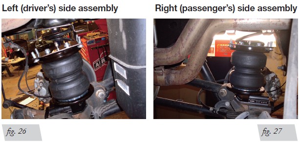
6. Set the right (passenger’s) side assembly into position in the same way, indexing
the lower bracket with the tabs under the jounce bumper strike plate and, with
the exception of using the slot for the carriage bolt in the lower bracket, install the
carriage bolts in the same manner. Torque both sides of the lower bracket hardware
evenly to 31 lb.-ft. (42Nm), making sure the tabs are still indexed under the jounce
bumper strike plate. Figures 26 & 27 show the assemblies bolted into position.
NOTE: Fittings should be on the outside (tire side) of the assemblies.
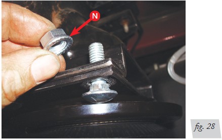
7. Raise the axle back up while aligning the air spring mounting plate’s carriage bolts,
with the frame mounting bracket holes. Cap all carriage bolts, once in position,
with 3/8” serrated lock nuts (N) and torque all the installed nuts to 31 lb.-ft. (42Nm)
(Fig. 28).
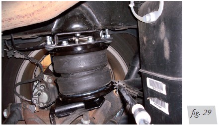
8. Left (driver’s) side shown with the assembly bolted up to the frame bracket (Fig. 29).
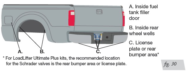
Installing the Air Lines
Air lines are routed from the air springs to Schrader valves. LoadLifter 5000 Series air
lines come in two styles: nylon and braided stainless steel. Begin by choosing locations for the Schrader valves and drill a 5/16” (8mm) hole, if necessary (Fig. 30).
CAUTION: KEEP AT LEAST 6” (152MM) OF CLEARANCE BETWEEN ALL AIR LINES AND THE EXHAUST SYSTEM. AVOID SHARP BENDS AND EDGES.
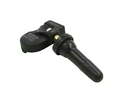
INSTALLING NYLON AIR LINES
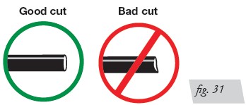
1. Cut the air line in half. Make clean, square cuts with a razor blade or hose cutter
(Fig. 31). Do not use scissors or wire cutters.
2. Use zip ties to secure the air line to fixed points along the chassis. Do not pinch or kink the air line. The minimum bend radius for the air line is 1” (25mm). Leave at least 2” (51mm) of slack in the air line to allow for any movement that might pull on the air line.
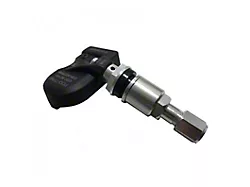
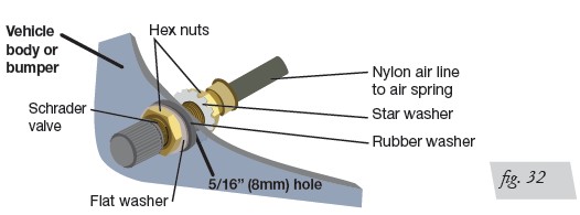
3. Install the Schrader valve in the chosen location (Fig. 32).
INSTALLING BRAIDED STAINLESS STEEL AIR LINES
CAUTION: KEEP THE AIR LINE AWAY FROM THE FUEL LINE, BRAKE LINES AND ELECTRICAL WIRES.
1. Use zip ties to secure the air line to fixed points along the chassis every 6” to 8” (152-203mm). Leave at least 2” (51mm) of slack to allow for any movement that might pull on the air line.
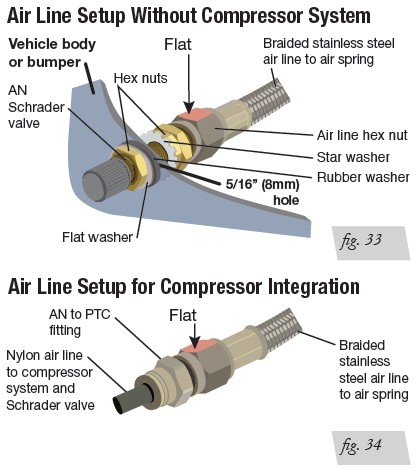
2. Tighten the air line hex nut finger tight, then use 2 wrenches to turn 1 additional flat (1/6 of one full turn). Do not overtighten (Figs. 33 or 34). The easiest way to tighten the fitting is off the vehicle. Install the Schrader valve in the chosen location.
3. Coil and secure any excess air line in an area where it will not be susceptible to damage. The braided stainless steel air line cannot be trimmed.
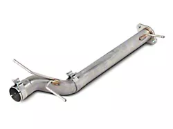
INSTALLING THE HEAT SHIELD
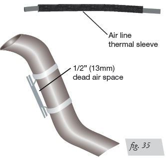
1. Attach the metal heat shield to the exhaust where it is closest to the air spring. Slide the air line thermal sleeve over the air line and place it where the air line is closest to the exhaust (Fig. 35).
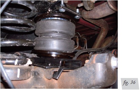
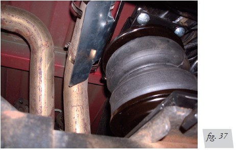
Finished Installation Photos
1. Back view of left (driver’s) side assembly (Fig. 36).
2. Back view of right (passenger’s) side assembly (Fig. 37).
Before Operating
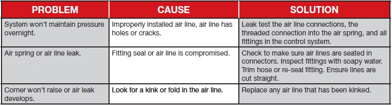
CHECKING FOR LEAKS
1. Inflate the air spring to 30 PSI (2BAR).
2. Spray all connections and the inflation valves with a solution of 1/5 liquid dish soap
and 4/5 water. Spot leaks easily by looking for bubbles in the soapy water.
3. After the test, deflate the springs to the minimum pressure required to restore the
system to normal ride height. Do not deflate to lower than 5 PSI (.34BAR).
4. Check the air pressure again after 24 hours. A 2-4 PSI (.14-.28BAR) loss after initial
installation is normal. Retest for leaks if the loss is more than 5 PSI (.34BAR).
FIXING LEAKS
1. If there is a problem with the swivel fitting:
a. Check the air line connection by deflating the spring and removing the line by
pulling the collar against the fitting and pulling firmly on the air line. Trim 1”
(25mm) off the end of the air line. Be sure the cut is clean and square (see Fig.
31). Reinsert the air line into the push-to-connect fitting.
b. Check the threaded connection by tightening the swivel fitting another half turn.
If it still leaks, deflate the air spring, remove the fitting, and re-coat the threads
with thread sealant. Reinstall by hand tightening as much as possible and then
use a wrench for an additional two turns.
2. If there is a problem with the inflation valve:
a. Check the valve core by tightening it with a valve core tool.
b. Check the air line by removing the air line from the barbed type fitting. Cut the
air line off a few inches in front of the fitting and use a pair of pliers or vice grips
to pull/twist the air line off of the fitting.
CAUTION
DO NOT CUT OFF THE AIR LINE COMPLETELY AS THIS WILL USUALLY NICK THE BARB AND RENDER THE FITTING USELESS.
3. If the preceding steps have not resolved the problem, call Air Lift customer service at (800) 248-0892.
INSTALLATION CHECKLIST
Clearance test - Inflate the air springs to 75-90 PSI (5.2-6.2BAR) and make sure there is at least 1/2” clearance from anything that might rub against each sleeve. Be sure to check the tire, brakes, frame, shock absorbers and brake cables.
Leak test before road test - Inflate the air springs to 75-90 PSI (5.2-6.2BAR) and check all connections for leaks. All leaks must be eliminated before the vehicle is road tested.
Heat test - Be sure there is sufficient clearance from heat sources, at least 6” (152mm) for air springs and air lines. If a heat shield was included in the kit, install it. If there is no heat shield, but one is required, call Air Lift customer service at (800) 248-0892.
Fastener test - Recheck all bolts for proper torque.
Road test - The vehicle should be road tested after the preceding tests. Inflate the springs to recommended driving pressures. Drive the vehicle 10 miles (16km) and recheck for clearance, loose fasteners and air leaks.
Operating instructions - If professionally installed, the installer should review the operating instructions with the owner. Be sure to provide the owner with all of the
POST-INSTALLATION CHECKLIST
Overnight leak down test - Recheck air pressure after the vehicle has been used for 24 hours. If the pressure has dropped more than 5 PSI (.34BAR), then there is a leak that must be fixed. Either fix the leak yourself or return to the installer for service.
Air pressure requirements - It is important to understand the air pressure requirements of the air spring system. Regardless of load, the air pressure should always be adjusted to maintain adequate ride height at all times while driving.
Thirty-day or 500-mile (800km) test -Recheck the air spring system after 30 days or 500 miles (800km), whichever comes first. If any part shows signs of rubbing or abrasion, the source should be identified and moved, if possible. If it is not possible to relocate the cause of the abrasion, the air spring may need to be remounted. If professionally installed, the installer should be consulted. Check all fasteners for tightness.
Product Use, Maintenance and Servicing

MAINTENANCE GUIDELINES
NOTE: By following the steps below, vehicle owners will obtain the longest life and best results from their air springs.
1. Check air pressure weekly.
2. Always maintain normal ride height. Never inflate beyond 100 PSI (6.9BAR).
3. If the system develops an air leak, use a soapy water solution (1/5 liquid dish soap and 4/5 water) to check all air line connections and the inflation valve core before deflating and removing the air spring.
CAUTION: FOR SAFETY AND TO PREVENT POSSIBLE DAMAGE TO THE VEHICLE, DO NOT EXCEED MAXIMUM GROSS VEHICLE WEIGHT RATING (GVWR), AS INDICATED BY THE VEHICLE MANUFACTURER. ALTHOUGH THE AIR SPRINGS ARE RATED AT A MAXIMUM INFLATION PRESSURE OF 100 PSI (6.9BAR), THE AIR PRESSURE ACTUALLY NEEDED IS DEPENDENT ON LOAD AND GVWR.
4. Loaded vehicles require at least 25 PSI (1.7BAR). A “loaded vehicle” refers to a vehicle with a heavy bed load, a trailer or both. Never exceed GVWR, regardless of air spring, air pressure or other load assist. The springs in this kit will support approximately 40 pounds of load (combined on both springs) for each 1 PSI (.07BAR) of pressure. The required air pressure will vary depending on the state of the original suspension. Operating the vehicle below the minimum air spring pressure will void the Air Lift warranty.
5. When increasing load, always adjust air pressure to maintain normal ride height. Increase or decrease pressure from the system as necessary to attain normal ride height for optimal ride and handling. Remember that loads carried behind the axle (including tongue loads) require more leveling force (pressure) than those carried directly over the axle.
6. Always add air to springs in small quantities, checking the pressure frequently.
7. Should it become necessary to raise the vehicle by the frame, make sure the system is at minimum pressure (5 PSI [.34BAR]) to reduce the tension on the suspension/ brake components. Use of on-board leveling systems do not require deflation or disconnection.
8. Periodically check the air spring system fasteners for tightness. Also, check the air springs for any signs of rubbing. Realign if necessary.
9. On occasion, give the air springs a hard spray with a garden hose to remove mud, sand, gravel or other debris.
TUNING THE AIR PRESSURE
Pressure determination comes down to three things — level vehicle, ride comfort, and stability.
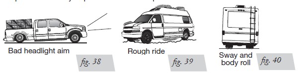
1. Level vehicle
If the vehicle’s headlights are shining into the trees or the vehicle is leaning to one side, then it is not level (fig. 17). Raise the air pressure to correct either of these problems and level the vehicle.
2. Ride comfort
If the vehicle has a rough and harsh ride it may be due to either too much pressure or not enough (fig. 18). Try different pressures to determine the best ride comfort.
3. Stability
Stability translates into safety and should be the priority, meaning the driver may need to sacrifice a perfectly level and comfortable ride. Stability issues include roll control, bounce, dive during braking and sponginess (fig. 19). Tuning out these problems usually requires an increase in pressure.
GUIDELINES FOR ADDING AIR
1. Start with the vehicle level or slightly above.
2. When in doubt, always add air.
3. For motorhomes, start with 50-100 PSI in the rear because it can be safely assumed that it is heavily loaded.
4. If the front of the vehicle dives while braking, increase the pressure in the front air bags, if equipped.
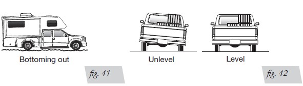
5. If it is ever suspected that the air bags have bottomed out, increase the pressure (fig. 20).
6. Adjust the pressure up and down to find the best ride.
7. If the vehicle rocks and rolls, adjust the air pressure to reduce movement.
8. It may be necessary to maintain different pressures on each side of the vehicle. Loads such as water, fuel, and appliances will cause the vehicle to be heavier on one side (fig. 21). As much as a 50 PSI difference is not uncommon.
Troubleshooting Guide