 FREE 1 to 3-Day Delivery on Orders $149+ Details
How to Install Air Lift Performance AirCell Non-Adjustable Load Support - Rear (09-18 RAM 1500) on your Dodge RAM
Installation Time
1 hours
Tools Required
- Hoist or floor jacks
- Safety stands
- Metric and standard sockets
- Metric and standard wrenches
- Ratchet
- Drill or Hand Grinder
- 9/16” Drill Bit
Important Safety Notice
The installation of this kit does not alter the Gross Vehicle Weight Rating (GVWR) or payload of the vehicle. Check your vehicle’s owner’s manual and do not exceed the maximum load listed for your vehicle.
Gross Vehicle Weight Rating: The maximum allowable weight of the fully loaded vehicle (including passengers and cargo). This number — along with other weight limits, as well as tire, rim size and inflation pressure data — is shown on the vehicle’s Safety Compliance Certification Label.
Payload: The combined, maximum allowable weight of cargo and pasengers that the truck is designed to carry. Payload is GVWR minus the Base Curb Weight.
Installation Diagram
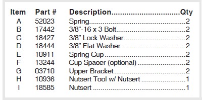
HARDWARE LIST
Installing the AirCell System
ASSEMBLING AND ATTACHING THE SYSTEM
1. Jack up the rear of the vehicle or raise on a hoist. Support the frame with safety stands. Lower the axle of the vehicle until the suspension is fully extended.
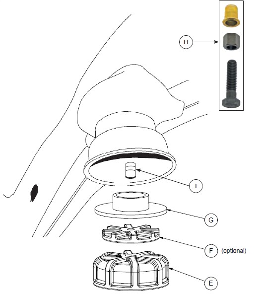
2. Remove the existing jounce bumpers on both sides (they just pull out from the mounting cup).
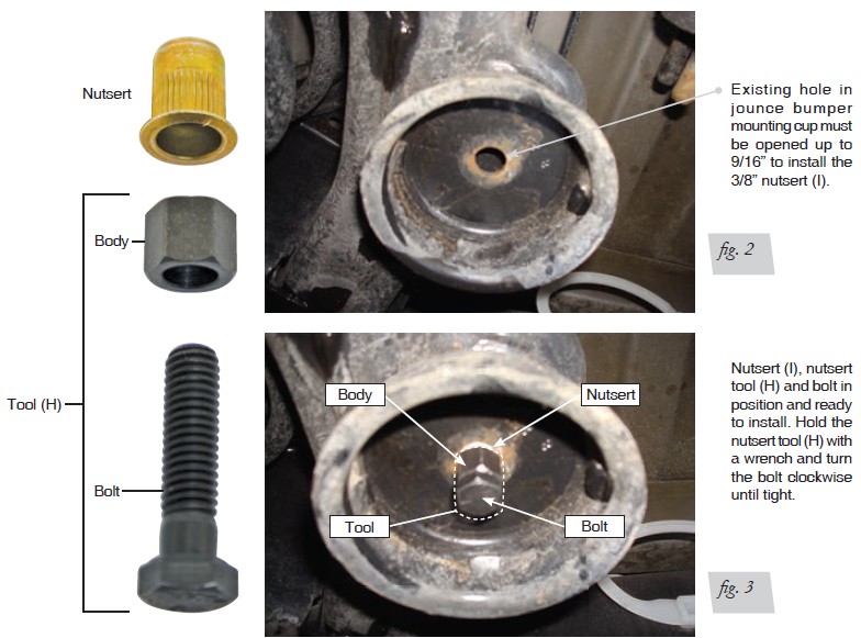
It will be necessary to install a nutsert (I) into the hole at the bottom of the jounce bumper mounting cup (fi g. 2). Use the nutsert tool (H) provided to install the nutsert (I) as follows:
3. It will be necessary to open the hole up by using a drill with a 9/16” drill bit. Or you can open the hole up slightly using a hand grinder (be sure to keep the hole as round as you can if you use the grinder). It is preferred that the hole be a tight fi t for the nutsert (I).
4. With a nutsert (I) on the nutsert tool (H), insert the nutsert (I) into the hole. While holding the body of the nutsert tool (H) with a wrench, turn the head of the bolt clockwise until the nut cannot be turned anymore (make sure it is tight) - (fi g. 3). Remove the nutsert tool (H) by turning the bolt counter clockwise.
NOTE: It may be hard to turn the bolt at fi rst when starting to install! Once the bolt breaks loose and starts to tighten, it will be easier as you tighten it while still holding the body of the nutsert tool (H).
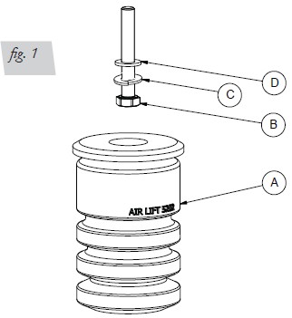
5. Attach the upper bracket (G)/spring cup (E) to the stock jounce bumper cup (with the new nutsert [I] installed) using a 3/8-16X3” bolt (B), 3/8 lock washer (C) and 3/8 flat washer (D). (fig. 1)
NOTE: The spring cup (E) has a slot in it, position the cup so the cup offsets to the rear of the vehicle. Tighten securely (fig. 1).
6. Insert the spring (A) into the spring cup (E). A twisting motion while pushing the spring (A) into the spring cup (E) will make the installation quicker. Make sure the spring (A) snaps into position into the spring cup (E).
NOTE: Applying grease or soap around the engagement flange of the spring (A) will help in aiding the spring (A) “snap” into the spring cup (E).
OPTIONAL: You can adjust the loaded height of the vehicle by adding the optional cup spacer (F) between the spring cup (E) and the upper bracket (G) (fig. 1).


