FREE 1 to 3-Day Delivery on Orders $149+ Details
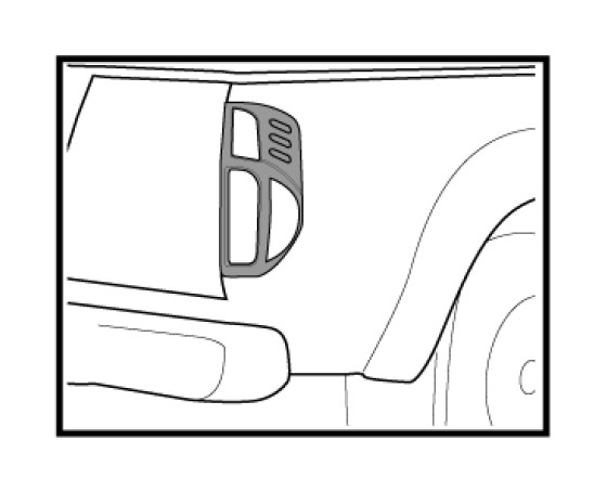
How to Install Carrichs Chrome Tail Light Covers on your Silverado
Installation of Taillight Inserts Accents
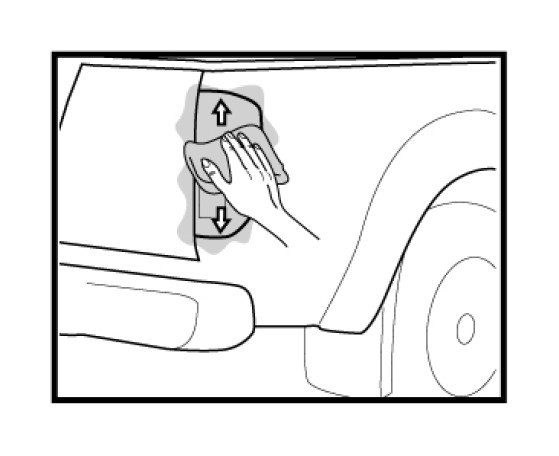
Step 1: Clean the affixing area by using soft cleaning cloth or sponge with mild detergent and water solution.
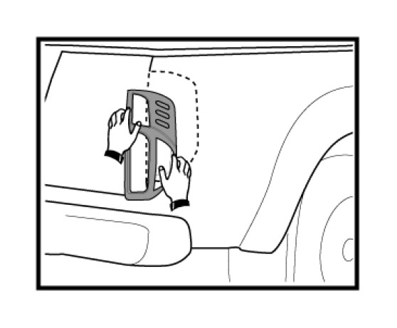
Step 2: Accurately measure the Taillight Inserts position prior application.
Repositioning of the double-sided tape can deteriorate their adhesive property.
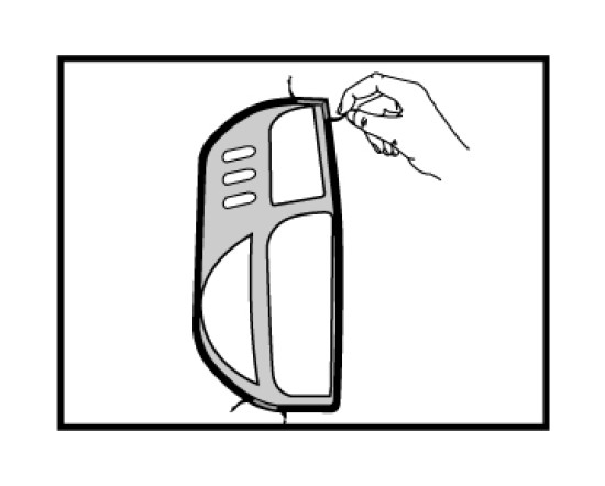
Step 3: Peel off the adhesive tape from the Taillight Inserts and gently position the insert on the original equipment part and press it firmly.
Step 4: Clean the part again to eliminate the flirts and grease.
CAUTIONS UPON INSTALLATION
The cautions mentioned hereunder are very important to install this product to prevent damage
1. Please thoroughly read installation instruction before attempting.
2. This product must be installed as specified in the manual. Failure to do so may result in improper lit which can cause damage or complete loss of the product, and will void the warranty.
3. For installation under temperature 15 degree Celsius or lower, it is strongly advised to use dryer to warm double-side tape to ensure proper adhesion.
4. After installation, make sure to allow a minimum of 24 hours before operating vehicle, or contact to water.
MAINTENANCE
1. To clean stain on the product, use soft cloth or sponge with mild detergent and water solution.
2. Avoid using chemicals or any abrasive-type cleanser to clean as they can cause damage to the product.
3. It is advised to wash vehicle often, if vehicles are used in the area where snow melting agent is frequently used or see breeze blow.