FREE 1 to 3-Day Delivery on Orders $149+ Details
How to Install AEM Electronics V2 Water/Methanol Injection Kit for Forced Induction Engines - Standard Controller (02-17 All) on your Dodge RAM
INSTALLATION DIAGRAM
NOTE: THIS KIT INCLUDES NEW STYLE INJECTOR NOZZLES THAT HAVE INTERNAL CHECK VALVES. AN EXTERNAL CHECK IS NO LONGER NEEDED OR INCLUDED IN THIS KIT.
Installation Checklist
The following list of steps is an overview of the installation process. A complete and more detailed list of each step including optional peripherals is defined later in this document.
> Install Tank
- Fasten with 4 of the 8 supplied #8 sheet metal screws along with the 4 large washers or the 5/16-18 bolts and Nylock nuts.
> Install Pump
- Select suitable location for pump near and below the lowest fluid level of tank.
- Fasten with 4 of the #8 sheet metal screws along with the 4 small washers or the #8-32 bolts and Nylock nuts.
- Cut supplied nylon hose with a sharp razor blade and install from tank to pump.
> Install Controller
- Disconnect ground side of battery during electronic installation.
- Find suitable location for controller inside driver’s compartment.
- Find location in driver’s field of view and install external LED.
- Follow the wire diagram and connect wires from supplied wire harness.
- Connect boost hose line to both controller and manifold pressure.
> Flush Tank
- Connect the remainder of hose to pump. (DO NOT CONNECT NOZZLE)
- Fill Tank with water (AEM recommends using Distilled Water).
- Turn on ignition power(Arm switch) to power on controller.
- Use Test button on controller to flush the tank into a separate container. Press and hold to activate the test function (repeat several times to completely flush system)
- Drain tank and proceed to next step.
> Connect Nozzle to System
- Select nozzle and connect to nylon hose.
- Fill tank with water.
- Use Test button on controller to test complete system.
> System Check
- While pushing the Test button ensure that no errors are reported and that the system is producing a gradually increasing flow out of the nozzle.
- This may require pressing the Test button multiple times to purge the system.
- Drain tank and fill with desired water/methanol mixture.
- DO NOT use a hydrocarbon fuel. Water/Methanol are the only supported fluids
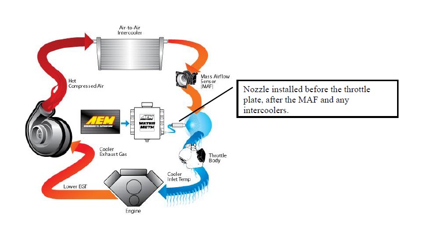
> Install Nozzle
- Find a suitable location to install nozzle. Nozzle must be mounted before the throttle plate. Nozzle should also be mounted after the MAF sensor if present. Nozzle must also be mounted after any intercoolers.
- Install nozzle, follow instructions for modifying intake to accept the nozzle.
- Cut and install nylon hose from pump to nozzle. Ensure that the hose is not resting, near, or running on any moving or “hot” parts.
> Tune Engine
- Engine tuning is usually required in order to maximize potential power gain.
Pump and Tank Install
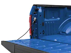
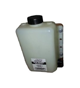
Find a suitable location to mount the tank and pump. The tank should be mounted such that it is below the injection point. The tank and pump must be mounted in the same area. Pump may be mounted on exterior of vehicle but should be mounted away from wheel wells or other areas where it will come into direct contact with water or road debris. Pump failures that have clearly been caused by exposure to water/mud/debris will not be covered under warranty. This includes but is not limited to, the bed of a truck, and the inside of the fender wells. Find a location where the pump will remain dry. Use 4 of the 8 supplied #8 sheet metal screws along with the 4 large washers or the 5/16-18 bolts and Nylock nuts to mount the 1-gallon tank.
(Optional 5 Gallon Tank Install)
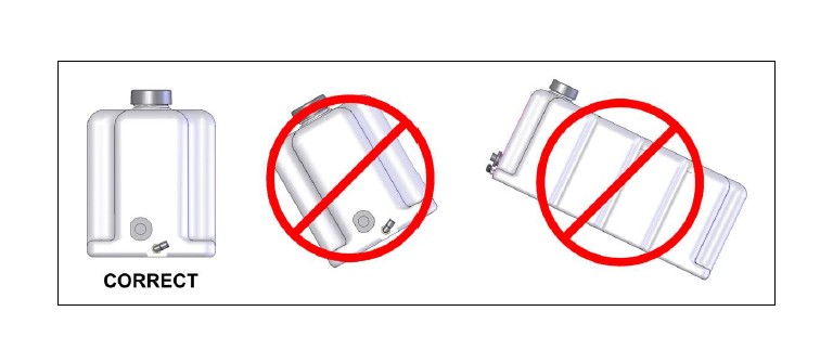
Before mounting the tank, check the area under the desired mounting location for fuel tanks, fuel lines, or any other obstructions. Mount the tank in an upright level position as shown below. Mark the four mounting points and drill with a 3/8” bit. Use the supplied 5/16-18 bolts, nuts, and large OD flat washers for mounting the tank into your vehicle. IMPORTANT: Use the supplied large OD washer to spread the load on the plastic mounting ears of the tank. DO NOT OVERTIGHTEN! Nuts should just be snug; they are locking nuts and will not loosen. Over-tightening will crack the plastic and cause leaks and void the warranty.
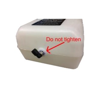
Note: All tanks are tested for leaks during assembly. A special sealant adhesive is used to bond the plastic tank to the metal fitting. DO NOT attempt to tighten the fitting any further!
The pump must be located in the same area as the tank and should be mounted at or below the lowest fluid level height.
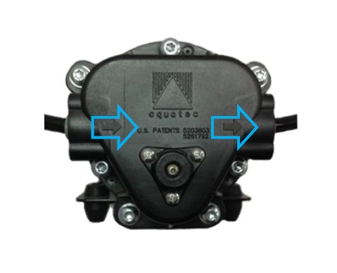
Take note of the direction of flow, indicated by the arrows on the pump body, when mounting the pump.
Use four #8 sheet metal screws along with the 4 small washers or the #8-32 bolts and nylock nuts to mount the pump. The pump can be mounted in any position horizontally or vertically. Once the tank and pump are mounted, cut the appropriate length of tubing needed to connect the outlet fitting on the tank to the inlet fitting on the pump. Make sure there are no sharp bends in the tubing. Cut the tubing to length with a clean perpendicular slice using a sharp razor blade, making sure the ends are clean and square. Push in the hose at the tank and pump to install. Make sure they are pushed in all the way and check with a light tug on the hose. Secure the hose to the chassis using sections of the supplied hose routing strip or with zip-ties.
Controller Install
The progressive controller is NOT waterproof and should NOT be mounted in the engine bay! Find a convenient location for the controller inside the driver’s compartment. The adjustment knobs should remain in an accessible location but still remain protected from possible water incursion. If you need to extend the wires to mount the controller use at least 16 AWG wire for the pump and controller ground circuits and 18 AWG for the remainder. The controller contains an externally accessible fuse, no additional fuses are required. Use the supplied zip-ties to mount the controller.
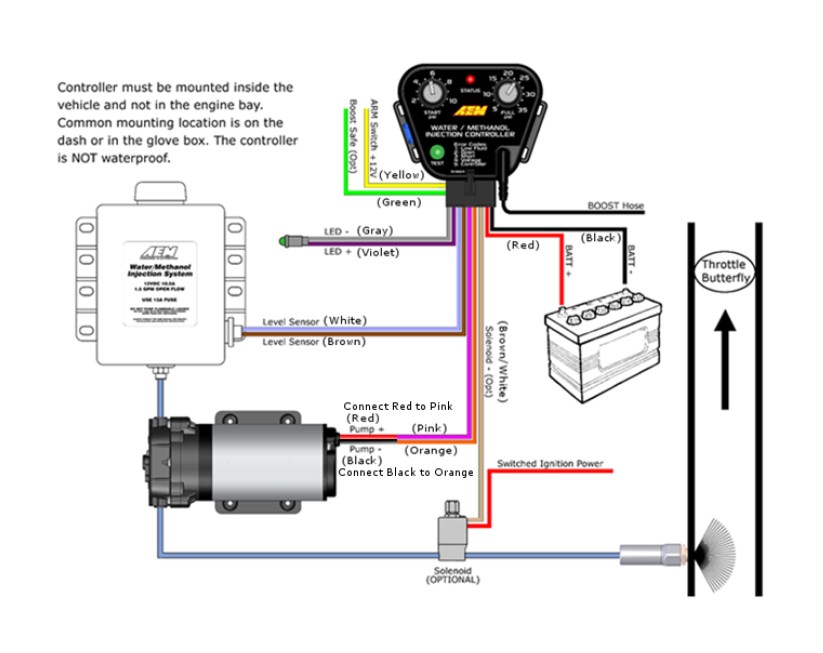
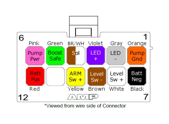
Progressive Controller Installation
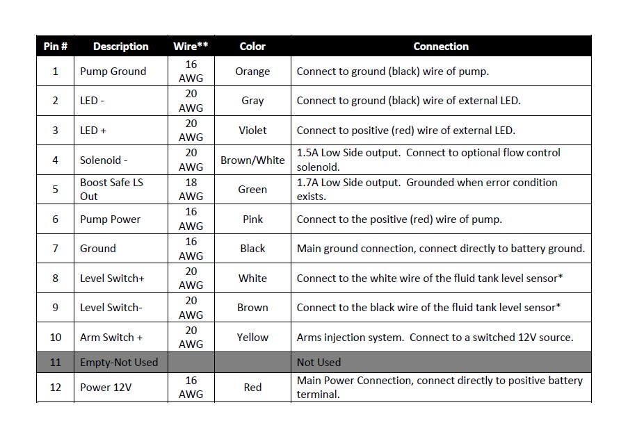
*Note: If fluid tank is equipped with previous generation level sensor, identified by having two black wires, then pins 8 (white) and 9 (brown) may be connected to either of the two black sensor wires. The polarity is unimportant.
**Note: If you need to extend the wires to mount the controller use at least 16 AWG wire for the pump and controller ground circuits and 18 AWG for the remainder.
External LED Install
Find a suitable location in the driver’s line of sight to mount the external LED. Mount the LED and run the wires to the controller. The LED indicates the operation of the controller. If the pump is off and there are no errors the LED will be off. If there are no errors and the pump is on the LED intensity will vary with the pump speed. If there are any errors they will be indicated by flashing the LED.
Boost Pressure Hose
Using the supplied vacuum tee and rubber hose, tap into a manifold pressure (vacuum/boost) line.
Pump/Tank Flush
After all wires are hooked up, add water to the tank and with the hose pointed into a container, press and hold the “TEST” push button on the controller module. The “TEST” button can be used to test the system. The pump speed will gradually increase from zero to full speed over 3 seconds, and then remain full for another 3 seconds before stopping. Repeat the “TEST” button procedure until you are sure the system is free of any debris that may have been in the lines or tank. Drain the water out of the tank and refer to the next section on installing the nozzle.
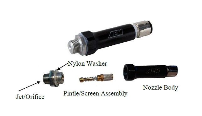
Nozzle Selection and Assembly
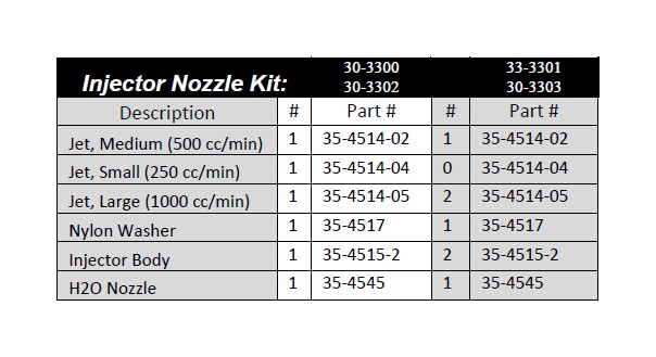
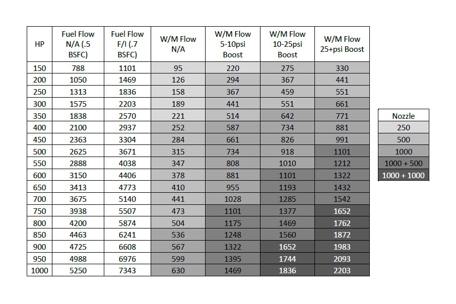
This injection kit includes three different sized injection jets that cover a very large range of horsepower levels. Use the following chart to select the appropriate jet for your power level. The kit comes with one medium nozzle already preassembled.
The nozzles are serviceable and can be disassembled for cleaning. If you find excessive debris in the screen, check your tank for contamination. When installing the screen it is only necessary to be slightly tighter than finger tight. Do not over-tighten. The nylon washers are reusable but a spare is included.
Nozzle Mounting
Select the location where the nozzle will be installed. Nozzle should be mounted such that it is higher than the tank. Nozzle must be mounted before the throttle plate. Nozzle should also be mounted after the MAF sensor if present. Nozzle must also be mounted after any intercoolers. In most instances, mounting the nozzle 6-8” ahead of the throttle body provides an excellent combination of air charge cooling and combustion control.
In most instances, the air charge piping can be drilled and tapped for 1/8” NPT to directly mount the nozzle. If using thin walled tubing it’s suggested that a bung be welded to the piping. Mounting hole should be tapped deep enough to allow the end of the nozzle to be nearly flush with the interior of the intake once the nozzle is fully installed.
Pump/System Check
The “TEST” push button on the controller module can be used to test the system. Press and hold the button to activate the pump. The pump speed will gradually increase from zero to full speed over 3 seconds, and then remain full for another 3 seconds before stopping. When the button is released the controller will return to normal operation.
Add water to the tank and with the nozzle pointed into a container, press and hold the test button. The flow will start gradually and increase to a steady amount. If this happens then your system is connected properly. Check and repair any leaks. Drain the water out of the tank and install the nozzle.
Fluid Compatibility
Under NO circumstances should any hydrocarbon based fuel ever be used with this system. Water and Methanol are the ONLY fluids to be used.
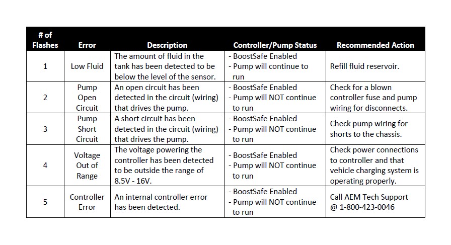
System Errors
The controller will continuously check for errors; when an error is detected it will be reported to the user by a flashing sequence of the external LED, as well as a corresponding red flashing sequence of the status LED. Damage to vehicle or engine may occur if these faults are not resolved immediately. The water-injection system may not operate properly or at all while an error condition exists. Please refer to the table below for further information.
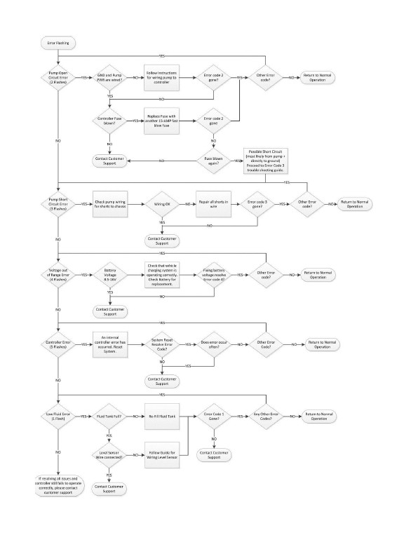
Troubleshooting Diagram
Controller
Settings
The AEM Water Methanol Injection Controller is a progressive type controller. This means that fluid will be injected in proportion to the amount of boost that is detected by the internal MAP sensor. In other words, more boost equals more fluid. It is therefore imperative that the vacuum/pressure connection be made properly and securely or vehicle/engine damage could occur. In addition, the controller will automatically compensate for any fluctuations in battery voltage variations to ensure consistent flow under all conditions.
The two knobs on the face of the controller dictate at what manifold (boost) pressure minimum fluid injection starts and at what pressure maximum/full fluid injection occurs. Fluid injection will ‘progressively’ increase between these two points as set by the adjustment knobs.
The “Start PSI” dial has a range from 1 psig (full counterclockwise rotation) to 11 psig (full clockwise rotation). The “Full PSI” dial has a range of 5 psig (full counterclockwise rotation) to 35 psig (full clockwise rotation). It is suggested to adjust the “Start PSI” value by setting the dial to approximately 25% of the vehicles maximum boost. Adjust the full-in value to your maximum possible boost. These are only suggestions; improper use or setting could result in engine or vehicle damage -- please consult your tuner.
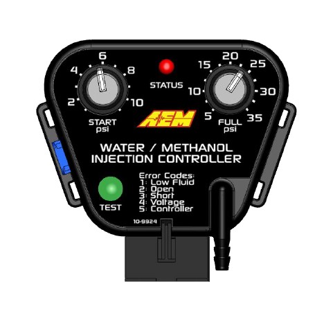
Status LED
The controller has an on-board Status LED. This will mimic the operation of the external LED. Upon startup the current mode is flashed in green on the status LED. It will flash error codes in red as well as illuminate with varying intensity as a function of flow in green.
Fuse
The controller has an externally accessible fuse. The controller itself will turn on and function, but the pump will not run without the fuse. If the controller is reporting an open circuit it may be that the fuse has blown, and or is not installed correctly. Use a 15 amp fast blow fuse for replacement purposes.
“Test” Button
The Test button feature is available to test the systems functionality. This feature should be used ONLY with the nozzle disconnected from the engine. This is to prevent unintentional pumping of fluid into the engine. To operate the test button press and hold. The pump speed will gradually increase from zero to full speed over 3 seconds, and then remain full for another 3 seconds before stopping. Flow should begin gradually and then hold at full pressure for a total test time of 6 seconds.
Short circuit self-diagnostics
There are two modes of pump-driver short circuit protection available. One can detect a short at any time but produces a slight buzzing in the pump. This should not be noticeable under most conditions, but can be turned off if it is objectionable. If turned off, a short circuit can only be detected when the pump is running.
To enable or disable this diagnostic (and the buzzing): Press and hold the “Test” button while applying power to the controller. The change is acknowledged by a single long flash of the status LED output and the external LED. Once the button is released the controller will continue to function normally. You can also tell what mode has been selected by listening for the buzzing sound in the pump. Repeating this operation will toggle between the two modes.
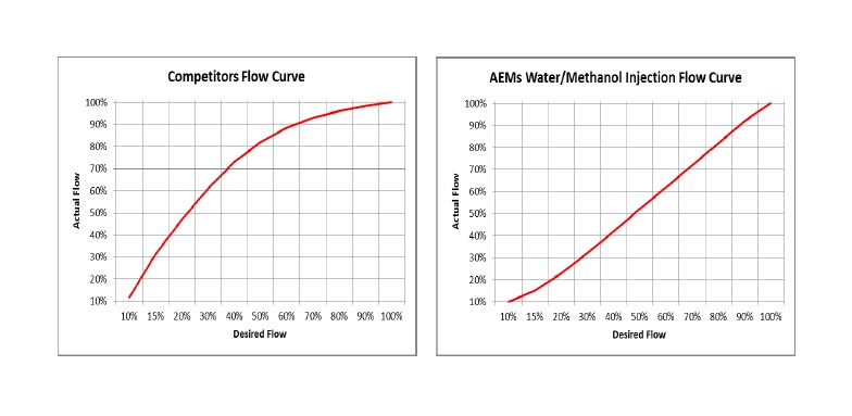
A More Linear Flow Output
AEM’s Water/Methanol Injection system delivers a linear flow rate as pump speed increases. This is unlike competitors’ systems that simply have a linear pump speed drive between start and full setting which results in a non-linear delivery of water/methanol. AEM’s system linearizes the flow, giving you better flow control and a more progressive delivery of water/methanol.
Boost-Safe Output (optional)
The progressive controller includes a Boost-Safe output (grounded when active) that activates whenever the system is armed and runs out of fluid or an error code is flashing. The green wire on the controller is the 1.7 amp switched ground. This wire can be hooked up to a solenoid that will vent waste gate pressure when activated. Apply 12v to the other side of the solenoid (AEM P/N 30-2400 or equivalent). This output can also be used to trigger a timing retard function in a standalone ECU or a CDI whenever the system runs out of fluid, thus protecting your engine. It is highly recommended that this feature be utilized.
Solenoid Driver (optional)
The progressive controller includes a Solenoid output (Brown with white strip wire grounded when active, 1.5A max) that activates whenever the system is pumping. The wire should be connected to the ground side of a solenoid, with the other end of the solenoid connected to switched ignition power. The solenoid should be installed after the pump and before the nozzle. For best results install the solenoid close to the nozzle.
Non-Progressive Operation (optional)
The progressive controller is capable of operating in a non-progressive manner, acting as a full on or full off type system. To set this up the “Full PSI” knob must be set to a lower value then the “Start PSI” knob. This means as soon as the boost exceeds the “Start PSI” threshold the pump will begin pumping at its maximum flow since it has passed both the start and the full requirements.
Engine Tuning
Water/methanol injection is generally not considered a bolt-on power adder for forced induction gasoline applications. Engine tuning is usually required in order to maximize potential power gain. Water/methanol injection allows for a more aggressive tune to be used while still using pump gas as your base fuel.
Using a 50/50 mix of water/methanol is recommended for the best combination of air charge cooling and detonation control. With conservative boost and timing, establish a base AFR that is one point higher than your final target AFR. For example, if your final target AFR with water/methanol injection is 11.0:1, set your base AFR to 12.0:1. Once the base AFR has been set, start injecting water/methanol and adjust the injection flow rate to achieve your final target AFR. For example, if before injection your base AFR is 12.0:1 and then during injection your AFR drops to 10.5:1, reduce the water/methanol flow rate until your final target AFR is reached. It is generally recommended that the flow rate of the injection system be changed in order to reach your target AFR and NOT your primary fueling. Injection flow rate adjustments can be made by changing your nozzle selection or by adjusting the “Start PSI” and “Full PSI” settings.
Once the injection flow rate is set to deliver your desired final AFR, boost and ignition timing can be increased to take advantage of the additional air charge cooling and detonation control. When injecting the correct amount, a 50/50 mix of water/methanol has been shown to provide an effective octane of over 110 when using a base fuel of 91-93 octane pump gas. A properly tuned water/methanol injection system will usually support a typical “race gas” engine tune.
Important Safety Notice Regarding Methanol
AEM strongly recommends that users never exceed a 50% methanol concentration when using any AEM Water Methanol system or component.
All AEM water/methanol injection systems and components (pump, lines, fittings, filter, flow sensor, tank, and nozzles) are 100% chemically compatible with methanol. However, for safety reasons we strongly recommend that users never use more than a 50% methanol concentration in our systems.
Methanol is a toxic and highly flammable chemical. 100% Methanol ignites easily and burns vigorously with an almost undetectable flame. Methanol can be absorbed through the skin and even small amounts can cause blindness or even death. Using this fluid at high pressures, without dilution, in an under-hood environment with nylon lines and push-to-connect fittings is very unsafe. The performance advantages of using greater than 50% methanol concentrations are small, if they exist at all. However, the safety issues are very real and far outweigh any perceived benefit of running high concentrations of methanol.
Note: AEM holds no responsibility for any engine damage or personal injury that results from the misuse of this product, including but not limited to injury or death caused by the mishandling of methanol.
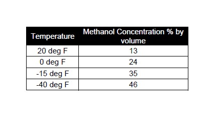
Cold Weather Operation
A Water/Methanol mix will also lower the freezing point of the fluid. Below is a chart with freezing points for different percentages of water/methanol mixtures.
Maintenance
The injector nozzle should be cleaned periodically. Disassemble the nozzle and clean it with a suitable cleaner until all debris is removed. If excessive contamination is found check the rest of the system for the source.