FREE 1 to 3-Day Delivery on Orders $149+ Details
How to Install AEM Brute Force Cold Air Intake - Gunmetal Gray on your Dodge Ram

Shop Parts in this Guide
PARTS LIST
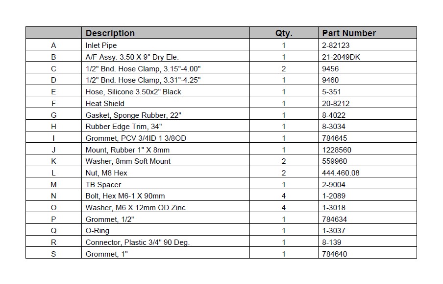
Read and understand these instructions BEFORE attempting to install this product. Failure to follow installation instructions and not using the provided hardware may damage the intake tube, throttle body and engine.
1. Preparing Vehicle
a. Make sure vehicle is parked on level surface.
b. Set parking brake.
c. If engine has run in the past two hours, let it cool down.
d. Disconnect negative battery terminal.
e. Do not discard stock components after removal of the factory system.
2. Removal of stock system
a. Release the four spring clips that hold down the top of the air box.
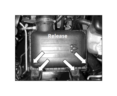
b. Loosen the hose clamp at the intake air resonator. Remove the rubber air hose and the air box lid.
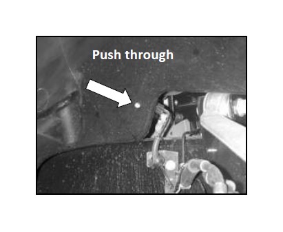
c. From inside the passenger side fender well, release the ABS wire holder. Push the wire holder through the hole, towards the engine. Remove the plastic fender liner by removing the eight self-tapping screws.
d. Remove the two bolts securing the bottom half of the air box.
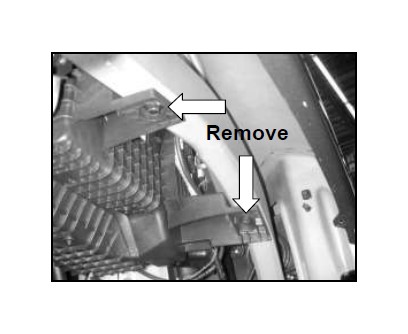
e. From inside the engine bay, remove the two remaining bolts securing the bottom half of the air box. Remove the bottom half of the air box and the air filter element.
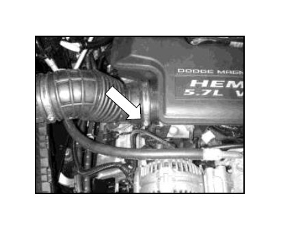
f. Unplug the inlet air temperature (IAT) sensor located on the front side of the intake air resonator.
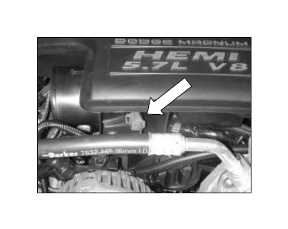
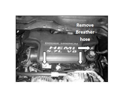
g. Remove the two bolts retaining the intake air resonator. Remove breather hose.
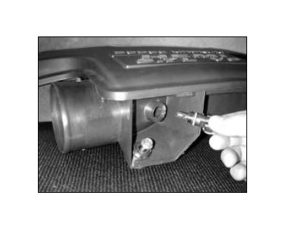
h. Remove the inlet air temperature (IAT) sensor from the intake resonator by gently twisting counter-clockwise. Remove the o-ring from the IAT sensor. Keep the o-ring for use if the vehicle ever needs to be returned to stock.
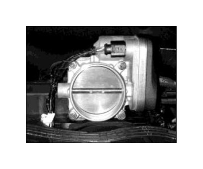
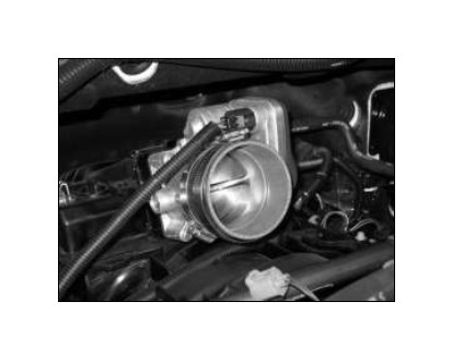
i. Remove the orange rubber gasket from the throttle body.
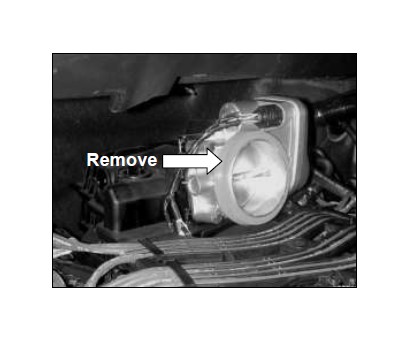
j. Remove the four bolts securing the throttle body. Unplug the electrical connector and remove the throttle body from the intake manifold.
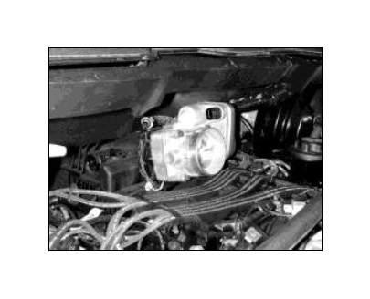
3. Installation of AEM® intake system.
a. When installing the intake system, do not completely tighten the hose clamps or mounting hardware until instructed to do so.
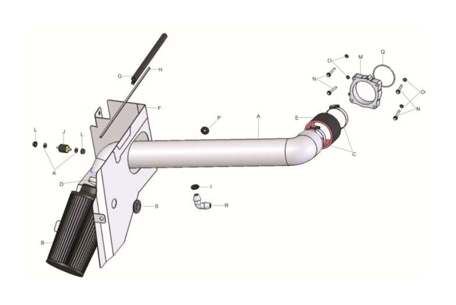
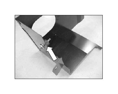
b. Install the supplied rubber mount into the heat shield as shown, place a M8 washer on the stud and a M8 nut to secure.
c. Install the supplied o-ring into the groove in the front of the throttle body spacer. Make sure the o-ring is properly seated in the groove around the entire circumference. Use a small amount of grease to trap the o-ring in place.
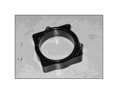
d. Install the throttle body spacer, aligning the pins on the intake manifold with the holes in the back of the throttle body spacer. The o-ring groove on the spacer should be facing forward.
e. Install the throttle body using the supplied M6 bolts and washers. Align the dowel pins on the throttle body spacer with the holes in the throttle body. Before installing the throttle body spacer, make sure the o-ring is seated. Reconnect the electrical connector.
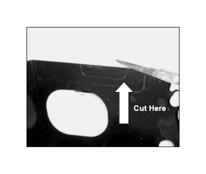
f. Trucks equipped with the optional under hood light on the passenger side, cut the corners on the small section of the top notch in the heat shield using a hacksaw or other suitable tool. Bend the tab back and forth until it breaks free. Clean up any sharp edges with a file. Vehicles not equipped with the under hood light, proceed to next step.
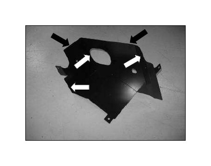
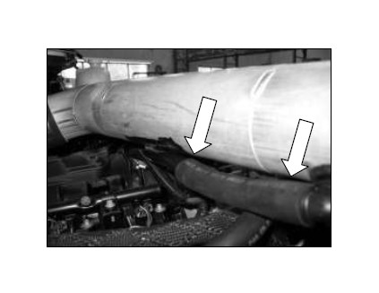
g. Install the rubber edge trim (PN: 8-4022) on the edges indicated with the white arrows. Install the sponge rubber gasket (PN: 8-3034) along the top of the heat shield indicated with black arrows.
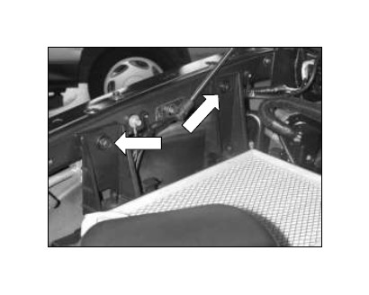
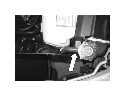
h. Loosen and remove the overflow reservoir mounting bolts.
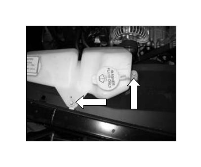
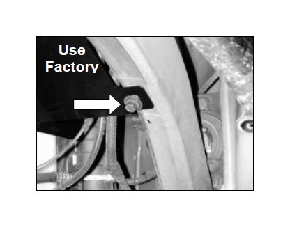
i. Disconnect the overflow tube to gain access to the upper radiator fan shroud bolt. Install the heat shield from inside the fender well. Place the front heat shield tab between the fan shroud and radiator end tank. Replace the factory bolt and overflow bottle. NOTE: On some models the windshield washer hose and wires can be run under the heat shield.
j. The lower heat shield mounting tab will line up with the lower air box mounting hole. Loosely secure the mounting tab with one of the original bolts.
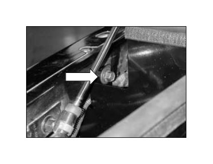
k. The rear mounting tab on the heat shield will line up with one of the lower air box mounting holes. Install one of the original bolts. Adjust the heat shield for best fitment then tighten the three mounting bolts.
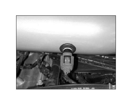
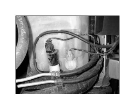
l. Install the supplied IAT grommet into the inlet pipe. Insert the factory IAT sensor into the grommet. Use care to avoid pushing the grommet into the pipe.
m. Loosely install the coupler and hose clamps onto the throttle body. Secure with provided hose clamps.
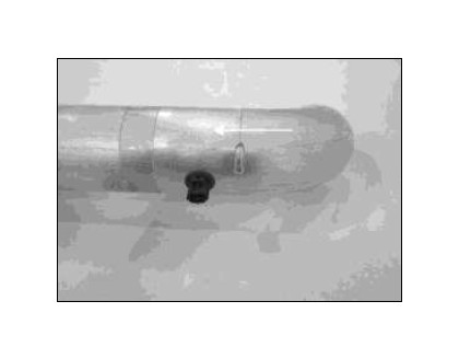
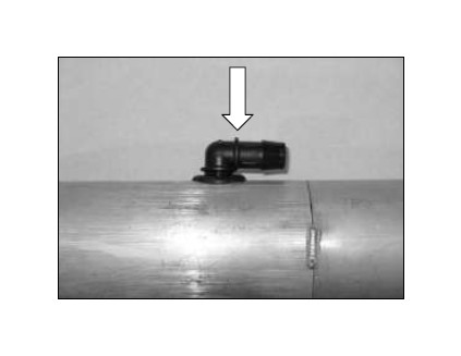
n. Insert the 1” grommet into the pipe. Insert the 90 degree plastic connector into the grommet. Be careful not to push the grommet through the pipe.
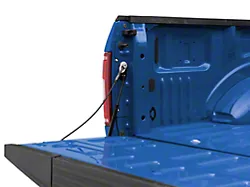
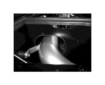
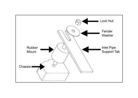
o. Insert the pipe as shown. Line up the support bracket to the rubber mount and secure. See diagram on next page.
Proper installation of rubber mount assembly.
p. Reconnect the wire harness to the IAT sensor. Do not push the grommet through the pipe.
q. Reconnect the PCV breather hose to the 90 degree fitting from step 3n. Check for clearance against the inlet pipe.
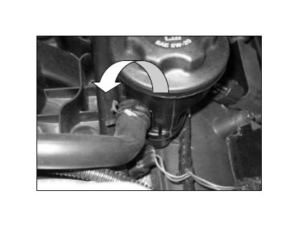
r. To increase the clearance of the breather hose and the inlet pipe, rotate the breather line at the PCV outlet counter clockwise. Release the spring clamp to rotate.
s. Install the air filter from inside the fender well. Slide the air filter on to the pipe until it stops. Secure with the supplied hose clamp. Make sure the windshield washer wires and hose do not come into contact with the air filter.
4. If the air filter is rubbing the windshield washer hose and wires; remove the filter and follow the instructions below. If the air filter does not rub the lines and wires, proceed to step 5.
a. Unplug the wire connectors going to the windshield washer fluid pump and level indicator. Unplug the washer fluid hose. Block the nipple on the pump to prevent the washer fluid from draining.
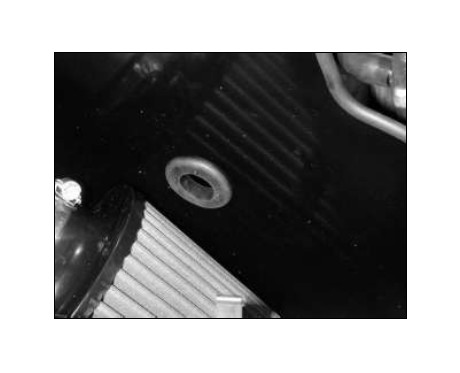
b. Pass both connectors through the supplied large grommet and then through the hole in the heat shield. Reconnect wire connectors and washer fluid hose to the washer fluid reservoir.
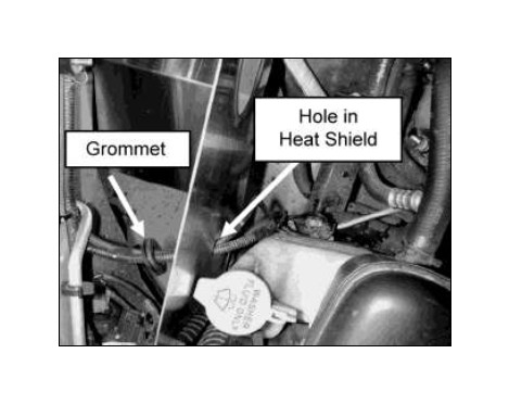
c. Install the rubber grommet in to the hole in the heat shield. Make sure the groove in the grommet is properly seated in the heat shield.
d. Install the air filter. Adjust the windshield washer hose and wires so they do not rub against the air filter.
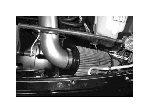
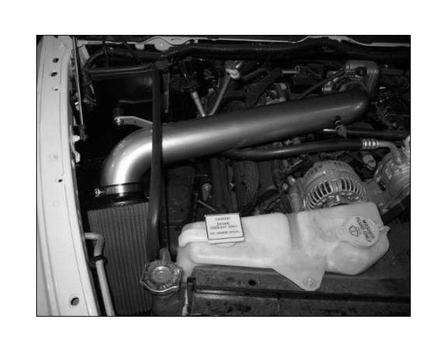
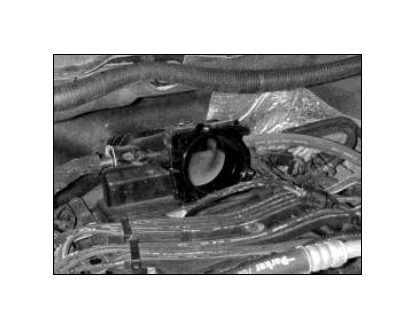
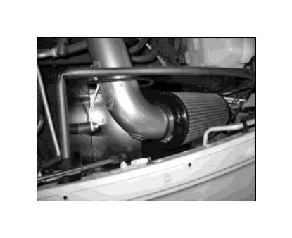
AEM® intake system installed
5. Reassemble Vehicle
a. Position the inlet pipes for the best fitment. Be sure that the pipes or any other components do not contact any part of the vehicle. Tighten the rubber mount, all bolts, and hose clamps.
b. Check for proper hood clearance. Re-adjust pipes if necessary and re-tighten them.
c. Inspect the engine bay for any loose tools and check that all fasteners that were moved or removed are properly tightened.
d. Reconnect negative battery terminals and start engine. Let the vehicle idle for 3 minutes. Perform a final inspection before driving the vehicle.
6. CARB Sticker Placement
a. The C.A.R.B. exemption sticker, (attached), must be visible under the hood so that an emissions inspector can see it when the vehicle is required to be tested for emissions. California requires testing every two years, other states may vary.
7. Service and Maintenance
a. It is recommended that you service your AEM® Dryflow™ filter every 20,000 miles for optimum performance. Use AEM Dryflow cleaning kit part # 21-110.
b. Use aluminum polish to clean your polished AEM intake tube.
c. Use window cleaner to clean your powder coated AEM intake tube. (NOTE: DO NOT USE aluminum polish on powder coated AEM intake tubes)