FREE 1 to 3-Day Delivery on Orders $149+ Details
How to Install Tuff Country 2 in. Leveling Kit on your Dodge Ram
Tools Required
- Torque wrench
- Standard socket set
- Standard wrench set
- Metric socket set
- Metric wrench set
- Tape measure
- Hydraulic floor jacks
Important information that needs to be read before installation begins:
Please be aware that some Dodge Ram owners may experience a vibration in the front end or a violent shaking vibration of the front wheels when going over a bump at certain speeds. This is due to the front differential and suspension when Dodge Ram trucks are in 4x4 mode. These two symptoms are often lumped together and called a "death wobble" however it is actually two different problems with the Ram Truck.
The 4HI mode vibration is a vibration or shudder that occurs when accelerating in 4x4 high mode. This symptom appears isolated to 2014 1500 non-Mega Cab model trucks and only when in 4-hi mode. Dodge could not discover why their stock trucks would do this for some customers and not others so the final official statement from Dodge was that there is no problem and that all of the new Rams will shudder or shake when in 4x4 high.
Therefore, after installing this kit on your Dodge Ram truck, if you experience either of the two symptoms mentioned above, Tuff Country recommends two options. 1). Remove the kit from the vehicle and send it back to the company you purchased it from for a full refund or 2). Install High angle CV joints that will stabilize the factory vehicles issues.
This Leveling kit comes with (1) installation manual and some post installation procedure literature and it is the installers responsibility to make sure that the customer receives the post installation procedure literature. If a customer would like a copy of the installation manual, please have them visit our website at www.tuffcountry. com. Have them go to the customer care section to download these instructions. If you have any questions, please feel free to call us at (801) 280-2777.
Before installation begins, Tuff Country EZ-Ride Suspension highly recommends that the installer performs a test drive on the vehicle. During the test drive, check to see if there are any uncommon sounds or vibrations. If uncommon sounds or vibrations occur on the test drive, uncommon sounds or vibrations will be enhanced once the suspension system has been installed. Tuff Country EZ-Ride Suspension highly recommends notifying the customer prior to installation to inform the customer of these issues if they exist.
Make sure to use loctite on all new and stock hardware associated with the installation of this suspension system.
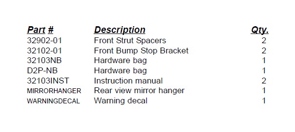
Hardware bag 32103NB includes:
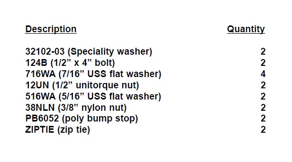
Hardware bag D2P-NB includes:

Please follow instructions carefully:
Before installation begins, measure from the center of the hub, to the bottom of the fender well, and record measurements below.
Pre-installation measurements:
Driver side front:_________________________________
Passenger side front:_____________________________
At the end of the installation take the same measurements and compare to the pre-installation measurements.
Post-installation measurements:
Driver side front:_________________________________
Passenger side front:_____________________________
Front end installation:
1. To begin installation, block the rear tires of the vehicle so that the vehicle is stable and can’t roll backwards. Safely lift the front of the vehicle and support the vehicle with a pair of jack stands. Place a jack stand on both the driver and the passenger side. Next, remove the front wheels and tires from both sides.
2. Working on the driver side, place a hydraulic floor under the lower control arm and carefully raise up on the hydraulic floor jack until it makes contact with the lower control arm. Repeat procedure on the passenger side.
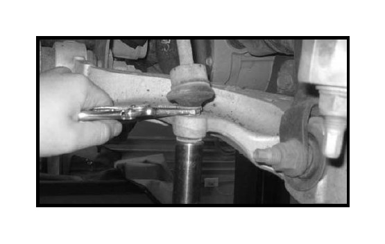
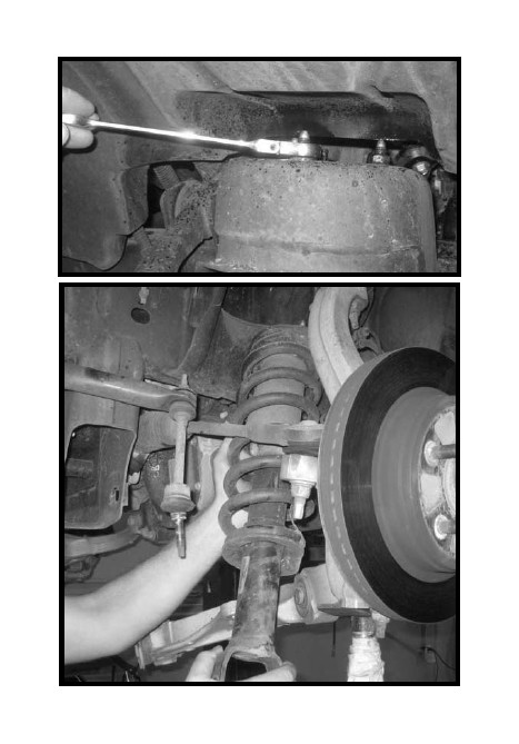
3. Working on the driver side, remove the sway bar end link hardware that attached the sway bar end link to the lower control arm. Save the hardware. Special note: To help make removal easier, place a wrench or a pair of needle nose vise grips on the end link so the end link does not spin. Repeat procedure on the passenger side.
4. Working on the driver side, remove the hardware that attaches the coil over to the lower control arm. Save the hardware. Repeat procedure on the passenger side.
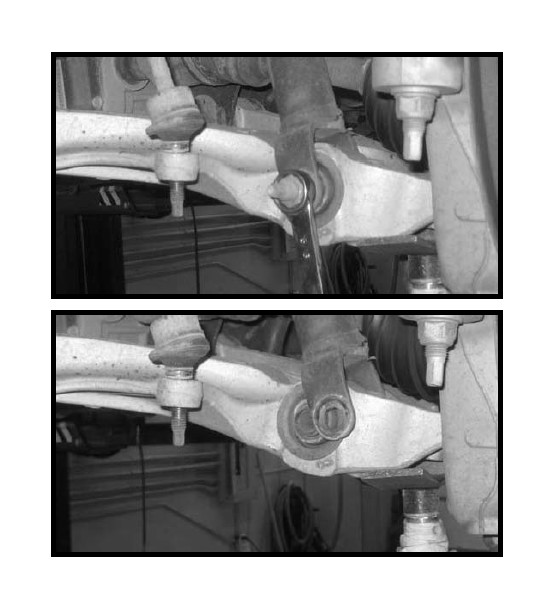
5. Working on the driver side, place a reference mark on the cam washer and cam stops that attach the lower control arm to the front and rear lower control arm mounts. Repeat procedure on the passenger side.
6. Working on the driver side, remove the hardware that attaches the lower control arm to the front and rear lower control arm mounts. Save the hardware. Repeat procedure on the passenger side. Special note: Let the lower control arms hang and rest on the hydraulic floor jacks.
7. Working on the driver side, remove the (3) nuts that attach the coil over into the upper location. Save the hardware. Remove and set the coil over aside. Repeat procedure on the passenger side.
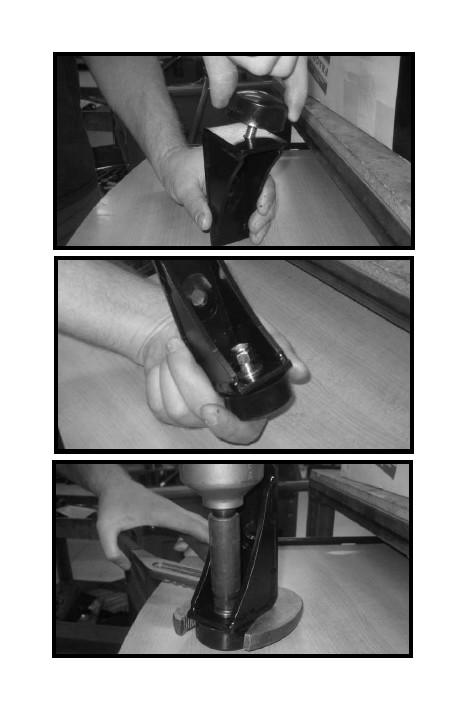
8. Install the new front spacers on the coil overs using the OE hardware. Make sure to use loctite and torque to 32 ft lbs.
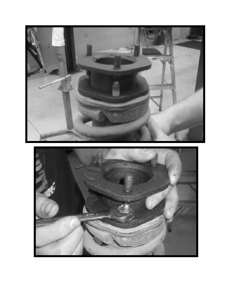
9. Locate (6) 3/8 nylon nuts and (6) 5/16” USS flat washers from hardware bag D2P-NB. Working on the driver side, install the newly modified coil over into the upper location and secure using the new hardware. Make sure to use loctite and torque to 32 ft lbs. Repeat procedure on the passenger side.
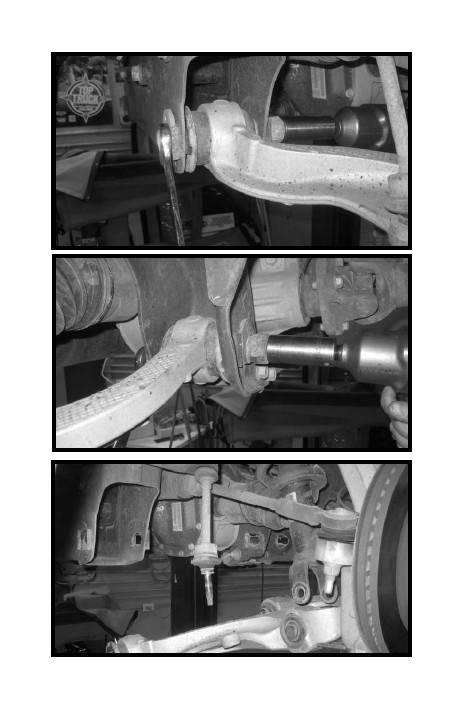
10. Working on the driver side, install the lower portion of the coil over to the lower control arm using the OE hardware. Do not tighten at this point. Repeat procedure on the passenger side.
11. Working on the driver side, install the lower control arm into the front and rear lower control arm pockets using the OE hardware. Make sure to use loctite, refer back to the marks that were scribed on the cam washer and cam stops and torque the front and rear mounting hardware to 105 ft lbs. Repeat procedure on the passenger side.
12. Locate the new front bump stop brackets. Also, locate (2) poly bump stops, (2) 3/8” nylon nuts and (2) 5/16” USS flat washers from hardware bag 32103NB. Install the new bump stops to the new bump stop brackets and secure using the new hardware. Make sure to use loctite and torque to 24 ft lbs.
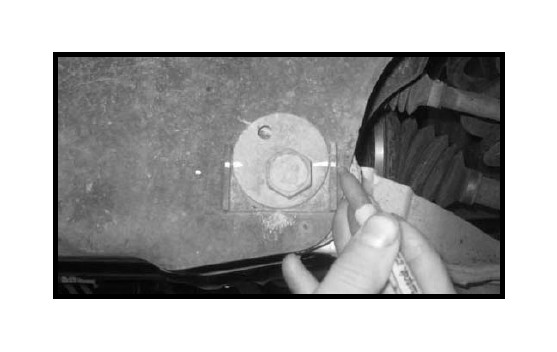
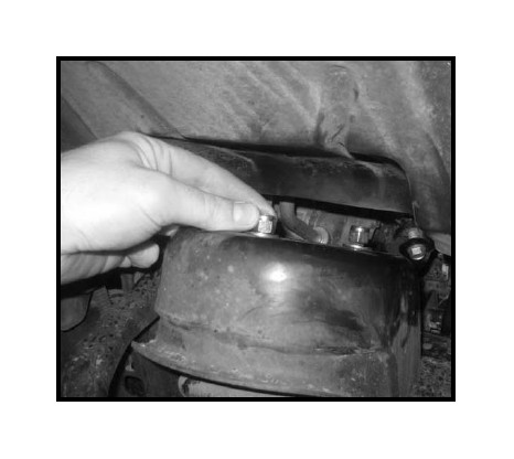
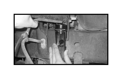
13. Locate (2) 32102-03 specialty washers, (2) 1/2” x 4” bolts, (4) 7/16” USS flat washers and (2) 1/2” unitorque nuts from hardware bag 32103NB. Working on the driver side, install the bump stop bracket to the frame rail under the rear portion of the upper control arm (hole provided) and secure using the new hardware. Special note, the specialty washer will be installed on the inside of the frame rail. Also, the special washer will fit into the dimple on the inside of the frame rail. Make sure to use loctite and torque to 65 ft lbs. Repeat procedure on the passenger side.
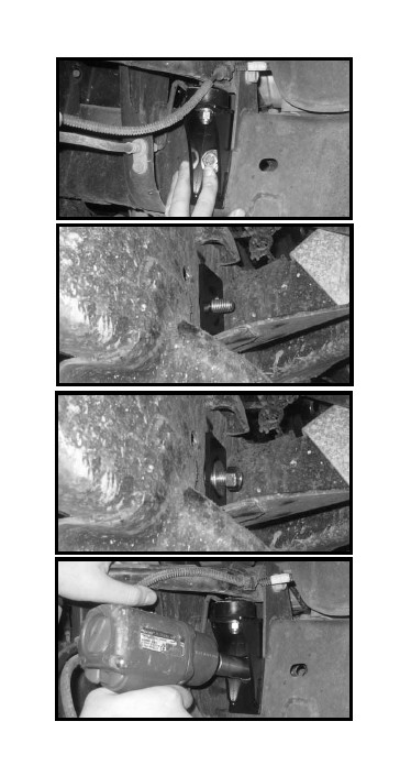
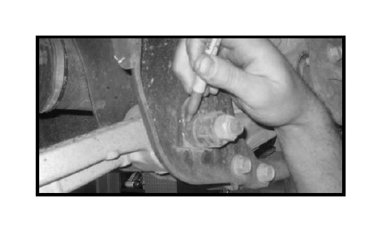
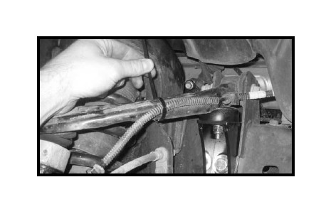
14. Locate the (2) zip ties in hardware bag 32103NB. Working on the driver side, zip tie the ABS line to the upper control arm so that ABS line does not get pinched between the upper control arm and the newly installed bump stop bracket. Repeat procedure on the passenger side.
15. Remove the hydraulic floor jacks from under the lower control arms and check and double check to make sure all steps were performed properly.
16. Install the tires and wheels and lower the front of the vehicle to the ground.
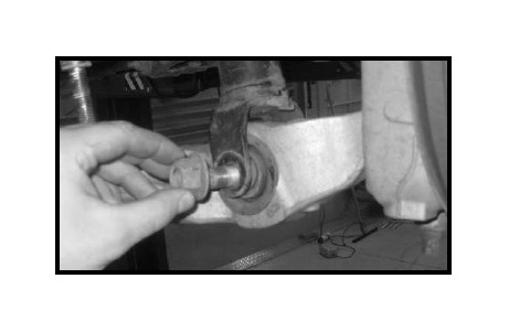
17. With the weight of the vehicle on the ground and working on the drivers side, install the front lower end link to the lower control arm using the OE hardware. Make sure to use loctite and torque to 40 ft lbs. Repeat procedure on the passenger side.
Congratulations, installation complete!
Special note: After the completion of the installation, Tuff Country EZ-Ride Suspension recommends taking the vehicle to an alignment shop and having a proper front end alignment performed.
Tuff Country EZ-Ride Suspension recommends that a complete re-torque is done on all bolts associated with this suspension system. It is the customers responsibility to make sure that a re-torque is performed on all hardware associated with this suspension system after the first 100 miles of installation. It is also the customers responsibility to do a complete re-torque after every 3000 miles or after every off road use. Neglect of following these steps could cause brackets to come loose and cause serious damage to the suspension system and to the vehicle.
Tuff Country EZ-Ride Suspension highly recommends that a copy of the rear view mirror hanger, the warning decal and a copy of the installation manual are given to the customer once the installation is completed and the customer picks up their vehicle.
If you have any questions or concerns, please feel free to contact Tuff Country or your local Tuff Country dealer.