 FREE 1 to 3-Day Delivery on Orders $149+ Details
How to Install Carr C Profile Light Bar - Black on your Silverado

Shop Parts in this Guide
MATERIALS NEEDED: Hammer, center punch, pencil. (Possible drill motor with a 3/8” drill bit)
MATERIALS FURNISHED: One hardware pack, two end castings, two Rota castings, Cross bar, instruction page.
C-PROFILE ROTA LIGHT BAR CUTTING INSTRUCTIONS
1. Two people will be needed for steps 8 and 9.
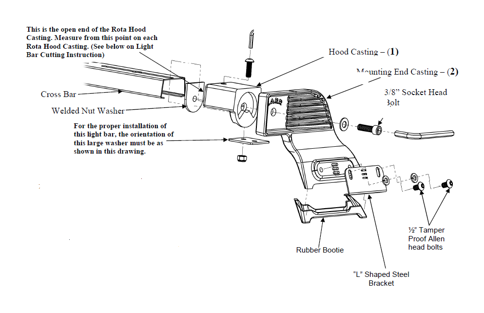
2. Place the black plastic booties on the feet of each Mounting End Casting (2).
3. Take the 3/8” Socket Bolts with the washers and place it through the holes in each
Mounting End Casting (2).
4. Place the Rota Hood Casting (1) against the face of casting (2). Take the Welded
Nut Washer and place that against the inside face of casting (1). Do this for both
sides.
5. With the 3/8” Socket bolts through castings (1&2), use the larger Allen Wrench and
tighten the assembly. Make sure that the top of casting (1) is level with the top of
casting (2).
6. Place each assembly in the rain gutters of your vehicle.
7. Now your assembly is ready for measuring.
8. Level each assembly so that the top flat area is parallel to the horizon.
9. Take a tape measure and measure the distance between each open end of each
Rota Hood Casting.
10. From that dimension add 3 inches.
11. Subtract that total from the total length of the bar, which is 56".
12. Take the difference and divide it by two.
13. The amount divided by two is the amount you will cut off each end of your bar.
14. Measure and mark a line on both ends of the steel bar using the above dimension
you have just figured.
15. Clamp one end of a bar into a vise. (Be careful not to scar the light bar).
16. Using a hacksaw, cut carefully along the marked lines. (If a vise is not available, put
the bar on a table, secure tightly and cut).
17. Repeat steps 15-17 to cut the other end of the bar.
WARNING!
THIS CARR LIGHT BAR IS DESIGNED TO HANDLE A TOTAL WEIGHT OF (20) LBS. ANY ADDITIONAL WEIGHT BEYOND THIS CAPACITY, MAY RESULT IN SERIOUS DAMAGE TO YOUR VEHICLE AND/OR ANOTHER VEHICLE.
WARNINGS!
> Do not over tighten the nuts and bolts or damage to the castings and or stripping of the threads could result.
> FOR SAFE AND PROPER USAGE OF THIS PRODUCT, THE MOUNTING INSTRUCTIONS MUST BE FOLLOWED CAREFULLY AND COMPLETELY.
> The manufacturer and distributor of this product are in no way responsible for the consumer’s failure to adhere to the warnings and directions of these instructions in the event of damage to the consumer’s vehicle, other properties and/or personal injury.
> DO NOT REMOVE the PVC tape from the light bar until cutting is completed. When cutting black bar leave plastic bag on and wrap a rag around bar before putting into a vise so no scratching of paint will result. Remove the PVC tape from the brackets (does not apply to black brackets). The light bar will not tighten properly unless the bar is straight across the cab.
1. IMPORTANT: Cut the crossbar FIRST before proceeding to the next step! Refer to the C-Profile Rota Light Bar Cutting Instructions.
2. With the slots in the Cross Bar, in the up position, take casting (1) and by squeezing the end of the bar, place casting (1) on the bar, until the inside top wall of the casting is flat against the bar.
3. Take a 5/16" Allen head screw and put it through the hole in casting (1), and the slot in the bar, with the head of the screw in the up position.
4. If your vehicle does not have a rain gutter, you MUST INSTALL Carr’s rain gutter kit before you continue. See Special Note for vehicles that do not have any rain gutters on the other side of these instructions.
5. IMPORTANT: For some trucks when the bar is cut and put into casting (1), there may not be a slot left in the bar. If this is the case, follow the next eleven steps.
a. Remove the Cross Bar from both assemblies. With the black booties placed on the bottom of castings (2), place the entire casting assembly into the rain gutter of the vehicle.
b. Position the foot of the “L” shaped steel brackets underneath the rain gutter and line up the vertical slot of the bracket with the tapped hole in the casting. Insert (2) ½" Tamper Proof Allen head bolts with lock washers through the “L” bracket securing the bracket to the support casting. DO NOT TIGHTEN
c. Place a screwdriver through the desired horizontal slot in the steel bracket, at the same time put the screwdriver into one of the three slots provided in the casting. (Proper selection of the slots in the bracket and the slots in the casting will result in a tighter fit on the vehicle).
d. Push the screwdriver against the casting and pry up against each bracket, one at a time until both the casting and brackets are tightly secured in place. Tighten the two Allen head bolts. CAUTION: Prying up excessively could result in bending of the bracket or stripping the slots in the castings.
e. Follow the same procedure in steps a, b, c, and d, to secure the other casting to rain gutter.
f. By squeezing the ends of the Cross Bar put the Cross Bar back inside each casting (1).
g. With the Cross Bar in each casting, take a pencil and using the holes on top of castings (1), mark a circle on each end of the bar.
h. Take the Cross Bar out and drill a 3/8" hole through each marked circle. Deburring may be necessary.
i. Put the bar back into the castings (2) and use the 5/16" Allen head screws and put them through the top holes in casting (1) and through the holes drilled in the bar. Take the two large flat washers and the 5/16-18 nylon lock nuts, as shown in diagram, and
securely tighten bar to castings (1). NOTE: Be sure that both large washers are completely underneath castings (1) in the orientation shown in the diagram.
j. The bar and casting assemblies should now be tightly secured to the vehicle.
k. Refer to step 18 for further instructions.
6. Take the larger washer and put it inside the bar, with the 5/16" Allen head screw, going through the washer. IMPORTANT: Be sure that the large washer is completely underneath casting (1) in the orientation shown in the diagram.
7. With the large washer in position, take a nylon lock nut and Allen wrench provided, and lightly tighten the bar to casting.
8. Follow the same procedure in steps 2, 3, 6 and7 to attach other casting to the bar.
9. With both of the casting assemblies lightly tightened to the bar, take the entire unit and place it into the rain gutters of your vehicle.
10. Loosen, DO NOT REMOVE hardware on bar and casting.
11. Slide the casting assemblies in or out on Cross Bar so that each casting assembly sets completely down and to the back of each rain gutter bracket. IMPORTANT: Make sure that the bar is centered and that the bar is evenly divided into each casting and that each casting is directly across from each other.
12. Once again, take the Allen wrench and tighten the bar securely to each casting assembly.
13. Position the foot of the L shaped steel brackets underneath the rain gutter and line up the vertical slots of the L Shaped Steel Bracket with the tapped holes in casting (2). Insert 2- ½" Tamper proof Allen head bolts with lock washers through the L Shaped Steel Bracket securing the bracket to casting (1). DO NOT TIGHTEN!
14. Place a screwdriver through the desired horizontal slot in the steel bracket, at the same time put the screwdriver into one of three slots provided in the casting. (Proper selection of the slots in the bracket and the slots in the casting will result in a tighter fit on the vehicle.).
15. Push the screwdriver against the casting and pry up against each bracket, one at a time, until both the casting and brackets are tightly secured in place. Tighten the two Tamper Proof Allen head bolts. CAUTION: Prying up excessively could result in bending of the bracket or stripping the slots in the castings.
16. Follow the same procedure in steps 13 - 15 to secure other casting to rain gutter.
17. The bar and casting assemblies should now be tightly secured to the vehicle.
18. CAUTION: WHEN LIGHTS ARE INSTALLED ON YOUR BAR AND YOU WANT TO LOOSEN YOUR BAR TO ROTATE THE BAR DOWN, BE CAREFUL NOT TO LOOSEN TOO MUCH BECAUSE LIGHTS COULD CRASH INTO THE CAB OF THE
TRUCK AND CAUSE DAMAGE TO THE TRUCK AND LIGHTS, AND DO NOT LOSE YOUR ALLEN WRENCH.
19. Your light bar hardware may settle in. After 2 or 3 weeks of use, go back and re-tighten all hardware. A periodic check on all hardware is recommended.
20. To maintain the luster of your light bar, apply a polish on a regular basis.


