FREE 1 to 3-Day Delivery on Orders $149+ Details
How to Install Rugged Ridge Nautic 12,500 lb. Winch w/ Steel Cable on your Silverado
Installing Your Winch
Read and understand all instructions and related Warnings, Cautions and Notices before attempting to install or use your Rugged Ridge® winch.
Installation requires purchase of a four—point mounting plate or properly equipped bumper unique to your vehicle. Dimensional footprint of your Rugged Ridge® winch is included with parts list at back of these instructions. Verify that the strength of the fasteners, mounting plate and vehicle frame attachment exceeds maximum rated pull of winch. Consult your retail distributor for available mounting plates and bumper options.
1. Align winch so that it sits flush and square on chosen mounting plate. Secure winch to mounting plate using 3/8" x 1-1/4" fasteners and fender washers supplied.
You may find it convenient at this time to feed the cable lead through the roller fairlead hole before you secure your winch plate/bumper. Note: Depending on your bumper, you may want to install your roller fairlead before you secure your winch. This will allow easy access to the roller fairlead back bolt.
Winch must be used with Fairlead to avoid damage to cable, spool and gears. Mount fairlead using supplied fasteners and assure it is centered over spool so cable will wind tightly and evenly in direction of arrow ONLY (see arrow on spool side—plate).
2. Mount solenoid box according to following illustration. Note: control box can be attached either above motor base or on top of spool tie bars. Use brackets and hardware supplied, securing threads with red Loctite ®. See following pages.
Solenoid Mounting Supplement 1
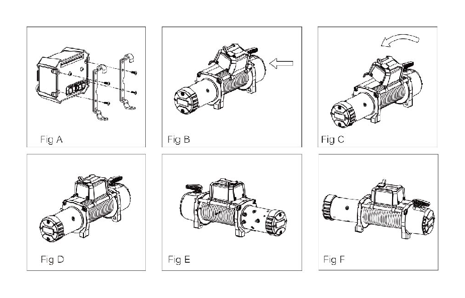
Step 1: Install the long mounting brackets with spaciers (hook facing forward) on the solenoid box and tighten the bolt. (Fig A )
Step 2: Place solenoid on top of tie—rods with hooks facing forward in desired location Secure by tightening the screws in the rear. (Fig B,C,D,E,F)Installation is now complete.Use the wiring diagram in instruction manual for further assembly.
Solenoid Mounting Supplement 2
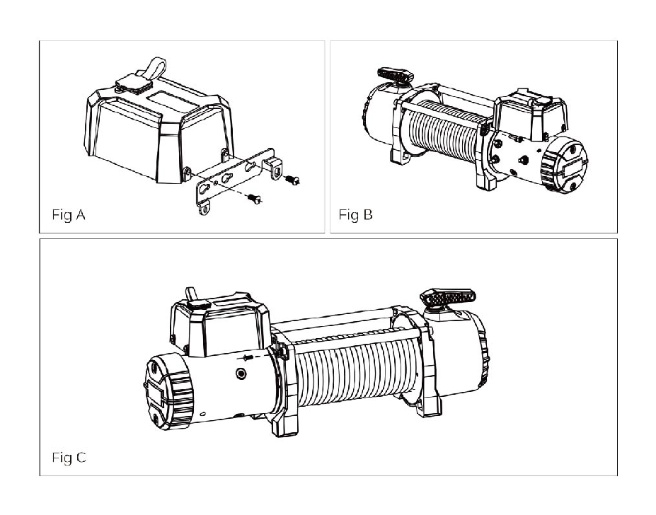
Step 1:Connect the long mounting bracket and L mounting bracket by bolt (Fig A) .
Step 2: Install the whole mounting bracket (hook facing forward) on the solenoid box and tighten the bolt ( Fig B ) .
Step 3: Place solenoid on top of tie—rods with hooks facing forward in desired location.Secure by tightrning the screws in the rear. (Fig C)Installation is now complete. Use the wiring diagram in instruction manual for further assembly.

Solenoid Mounting Supplement 3
Step 1:Loosen the bolt on the side of solenoid box and place the small mounting bracket at the side of solenoid box , tighten the bolt.(Fig A)
Step 2: Loosen the tie rod bolt at the motor side, and place the control box in the desired location, and then tighten the holt. (Fig B)
Step 3: Tighten the logo bar bolt at the motor side. Installation is complete. Use the wire diagram in the instruction manual for further assembly. (Fig C )
Solenoid Mounting Supplement 4
Step 1: Select the appropriate bracket hardware for your installation.Rugged Ridge supplies two over spool mounting options. Depending on your bumper,winch plate, or application, you will need to determine which bracket choice to use. The angled bracket allows the solenoid to be angled forward to ensure proper clearance of plug for hand controller relative to bumper overriders or stinger applications.
Step 2: Configure & attach brackets as shown for mounting of Solenoid Box over spool.
Step 3: Attach Solenoid Box to the tie bars over spool by hooking the Mounting Bracket around front tie bar and securing at the rear with the 2 screws provided,making sure all cables are located between the solenoid box and the tie bar.

3. Make solenoid box to vehicle battery connections after consulting wiring diagram and instructions.
To avoid risk of severe injury to eyes and body when working around batteries and electrical components:
• Always wear eye protection and remove watches, jewelry.
• Never lean over battery or connection being made.
• Leave remote switch disconnected to prevent inadvertent spool movement and accident.
• Never route electrical cables: across sharp edges or through door jams; through or near moving parts; near parts that become hot.
• If drilling or cable supports required, verify area is clear of fuel lines, brake lines and other electrical cables.
• Install insulating boots on all exposed terminal posts and assure wiring/cables remain insulated and protected from heat, vibration and wear.
Electrical Connection
For normal self-recovery work, your existing electrical system is adequate. A fully charged battery and proper connections are essential. Run the vehicle engine during winching operations to keep battery charged.
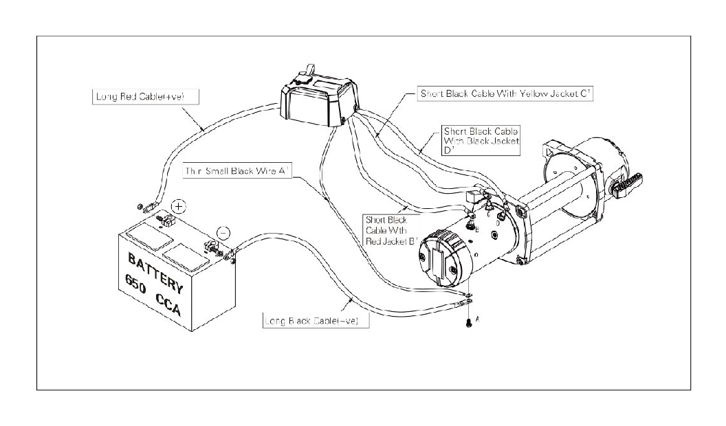
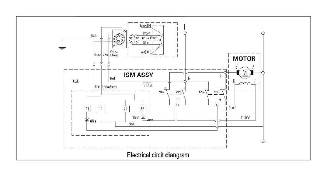
Ply doe attention to proper electrical cable connection as follows(refer to Diagram 1)
1 .Short black cable with red jacket (B)connecking to the red terminal (B)of the mokor.
2. Short black cable with yellow jacket (C') connecting to the yellow terminal (C)of the motor
3. Short black cable with black jacket (D')connecting to the black terminal (D)of the motor
4. Thin black cable (E)connecting to bottom terminal (A)of the motor
5. Long Black Cable(1.8m). one termini (A') connecting to the bottom terminal (A)Of the motor, and the other terminal negative( — )connecting to negative( • )terminal of battery
6. Long red cable positive( )connecting to positive( )terminal of battery
REMOTE CONTROL SWITCH
NOTE:
1 .Your battery must he kept in good condition.
2. Be sure battery cables are not drawn taught across any surfaces, which could possibly damage them
3. Corrosion on electrical connections will reduce performance or may cause a short.
4. Clean all connections especially in remote control switch and receptacle.
5. In salty environments use a silicone sealer to protect from corrosion.
6. Index the heads of the plate sutds into the keyhole slots on the back of the winch.
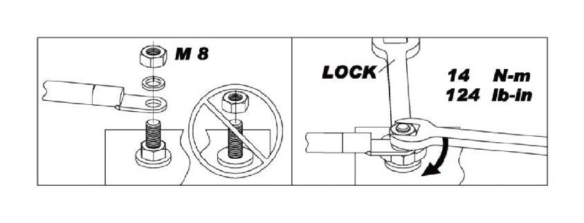
Motor Wire Nuts Mounting Instruction
Step 1:Do Not screw wire nuts too tight.
Step 2:Put a wrench on bottom nut when installing wire nuts to prevent movement of terminal stud and hold downnut. It' s helpful to avoid bolt broken during installation. See pictures below.
Rating and condition of vehicle battery will affect winch performance. Minimum required battery is 650 CCA, fully charged.
Corrosion on electrical connections and battery terminals will reduce power and winch performance. Keep battery charged, all connections clean and sealed with silicone—based sealer.
WINCH OPERATION
SUGGESTION:
The best way to get acquainted with how your winch operates is to make a few test runs before you actually need touse it. Plan your test in advance. Remember you can hear your winch as well as you can see it operate. Get to recognize the sound of a light steady pull, a heavy pull, and sounds caused by load jerking or shifting. Soon you will gain confidence in operating your winch and its use will become second nature to you.
OPERATING:
Pre/post op check list.
Check fasteners for torque before each outing.
Inspect wiring and make sure connections are tight before each outing.
Verify there is no chafing or cutting of wires.
Inspect rope for damage before and after each use.
Inspect remote for damage and function. Check range on wireless remote,
if applicable, replace battery if necessary.
Keep winch clean, remote socket covered and steel cable lightly lubricated.
Synthetic rope needs to be kept clean and free from any chemicals or dirt.
Refer to owners manual for more information.
NEVER operate winch with less than 10 wraps of synthetic rope or 6 wraps of steel cable around the drum. The terminal end is to prevent the rope from unraveling, it is NOT a load bearing attachment point. Improper instillation and/or spooling out to last layer will put a load on the terminal end and the rope will release from the terminal.
Always re—spool winch rope under a minimum 1000 lb. load before each use.
Always re—spool winch rope under a minimum 1000 lb. load before each use.
1 .Ensure the vehicle is secured by applying the parking brake or
chocking the wheels.
2. Pull out the winch cable the desired length and connect to an anchor point. The winch clutch allows rapid uncoiling of the cable for hooking onto the load or anchor point. The shifter tab located on the gear housing of the winch operates the clutch as follows:
(A) To disengage the clutch, move the clutch shifter tab to the ''OUT position. Cable may be free spooled off the drum.
(B) To engage the clutch, move the clutch shifter tab into the ''IN" position. The winch is now ready for pulling.
3. Recheck all cable rigging before proceeding.
4.Plug in the winch hand control. It is recommended that the winching operation taker place from the driver,s position to ensure safe
5.To commence winching operation.start vehicle engine.seiect neutral in transmission,maintain engine speed at idle.
6.Operate the remote control switch to IN or OUT until the vehicle has been retrieved.Regularly check the winch to ensure cable is winding onto the drum evenly.
Note:
1 .Never winch with your vehicle in gear or in park, which would damage your vehicle' s transmission.
2. Never wrap the cable around the object and hook onto the cable when winching.
3. Keep hands, clothing, hair and jewellery clear of the drum area and cable when winching.
4. Never use the winch if the cable is frayed, kinked or damaged.
5. Never allow anyone to stand near the cable, or in line with the cable behind the winch while it is under power. I f the
cable should slip or brake, it can suddenly whip back towards the winch, causing a hazard for anyone in the area. Always stand well to the side while winding.
6. Don' t leave the switch plugged in when winch is not in use.
7. Do not use as a hoist
8. Power out only to relieve slack on cable or rope.Excessive powering out can cause damage to internal components.
9. Do not use to hold loads.
10. Do not use to drop loads(example—unloading vehicles).
CHECK THE WINCH CAREFULLY AND THOROUGHLY BEFORE OPERATING!