FREE 1 to 3-Day Delivery on Orders $149+ Details
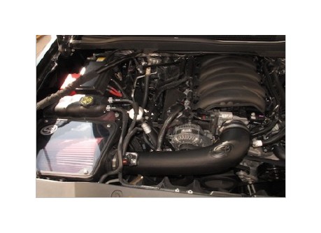
How to Install S & B Cold Air Intake w/ Oiled Cleanable Cotton Filter (14-17 5.3L Sierra 1500) on your GMC Sierra
Tools Required
- 8mm, 10mm, 13mm Wrench & Socket
- Pin Removal Tool or Flat Blade Screwdriver
- 7/16” Wrench and Socket
- 5/16” Nut Driver or Flat Blade Screwdriver
- Phillips Screwdriver
- 1 Set of Torx Wrenches & Allen Wrenches
- 1 Pair of Pliers or similar tool

Shop Parts in this Guide
- S&B Cold Air Intake with Oiled Cleanable Cotton Filter (14-16 5.3L Sierra 1500)
- S&B Cold Air Intake with Oiled Cleanable Cotton Filter (14-16 6.2L Sierra 1500)
- S&B Cold Air Intake with Dry Extendable Filter (14-16 5.3L Sierra 1500)
- S&B Cold Air Intake with Dry Extendable Filter (14-16 6.2L Sierra 1500)
NOTES
Kit may not fit with the following Aftermarket Parts installed:
• Body Lift or Lowering Kit
• Custom Hood
• Throttle Body Spacer/ Upgrade
BEFORE YOU START
• Please read the entire product guide before proceeding.
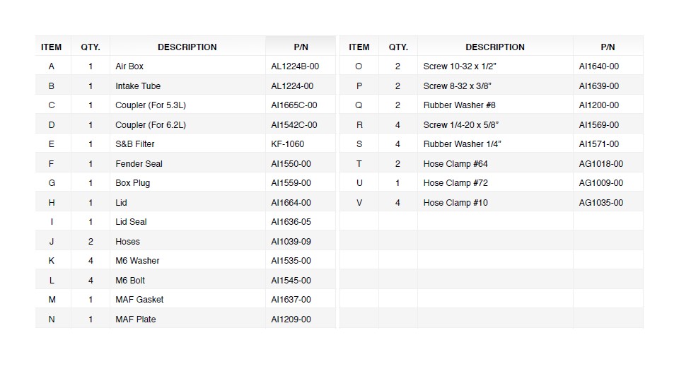
• Ensure all components listed on page 4 are present.
• If you are missing any of the components, call our customer support at (909) 947-0015.
• Do not work on your vehicle while engine is hot.
• Make sure the engine is turned off and the vehicle is in Park or the Parking Brake is set.
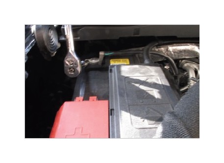
1. With the ignition switched off and the parking brake set, disconnect the negative battery cable on the passenger’s side. Note: Failure to disconnect the battery may cause the CEL to illuminate upon completion of the installation and subsequent operation. Do not skip this step!
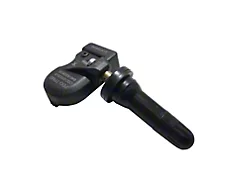
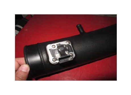
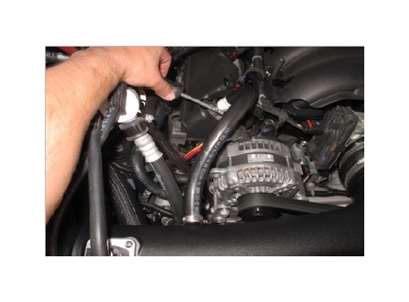
2. The sensor must be removed from the factory intake cover using a Torx bit.
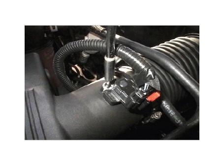
3. Once the sensor is removed, disconnect the sensor from the harness by pulling the Red tab out and pressing down on the release button while pulling out. Place the sensor in a safe location for later install.
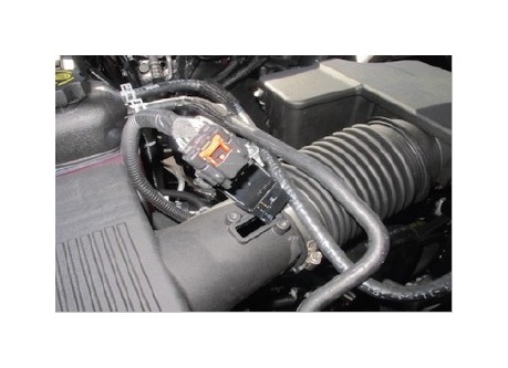
4. Use a nut driver to loosen the hose clamp on the factory air box cover.
5. Once the hose clamp is loose, pull tube to the right to remove from factory air box cover.
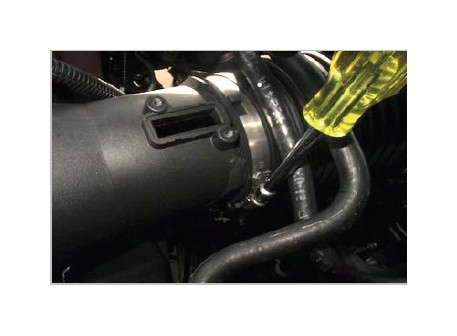
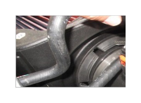
6a. Remove the factory hose from the OE resonator box by first pressing in the grey button up on the bottom.
6b. Continue from Step 6.
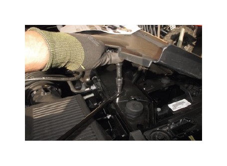
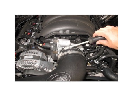
7. Loosen the hose clamp at the throttle body.
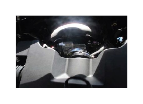
8. Remove the resonator box off the throttle body and out of the vehicle.
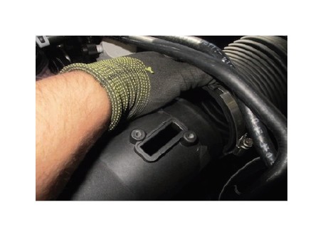
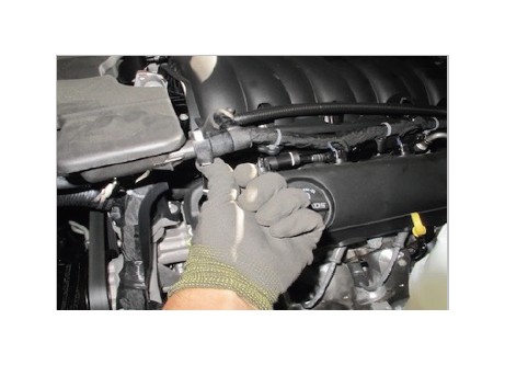
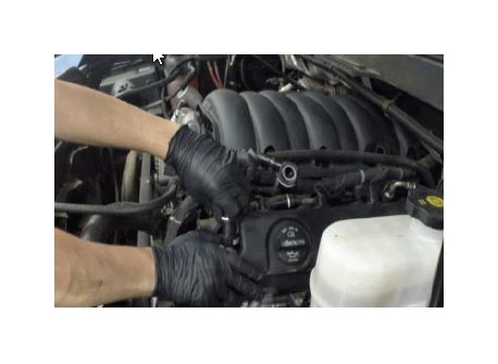
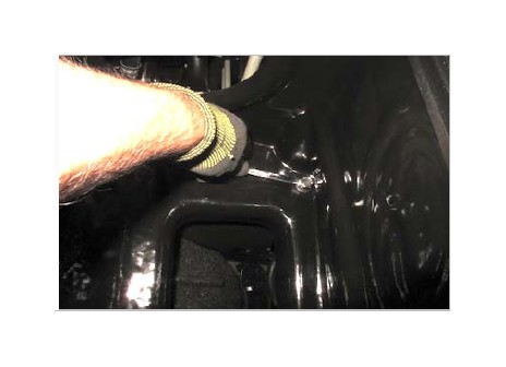
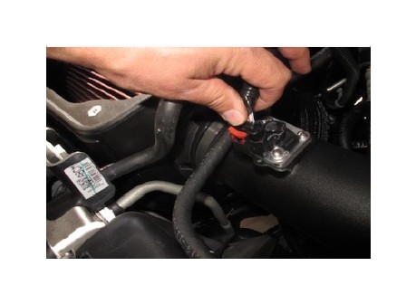
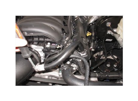
9. Remove both crankcase hoses from each valve cover by pressing in the grey button then lift up.
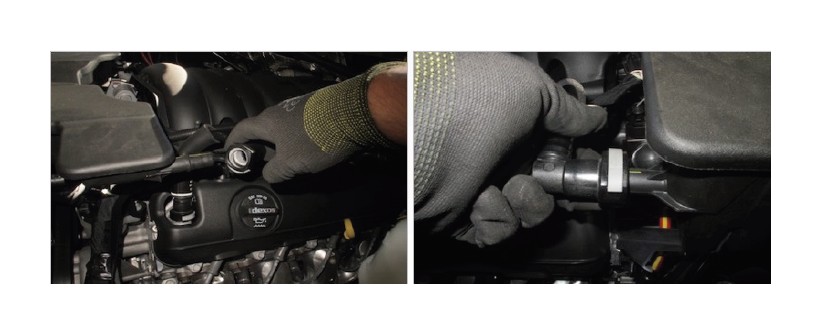
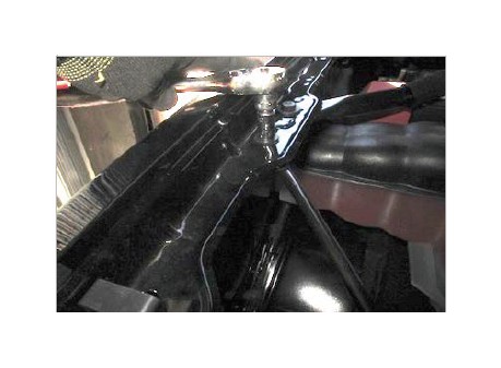
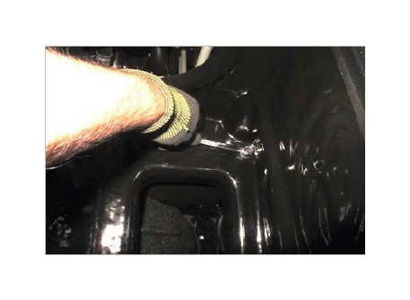
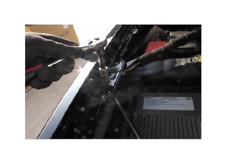
10. Remove the top bolt from the front cross bar using a 10mm socket.
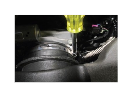
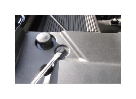
11. Remove the 4 plastic push pins on the far left side of the front liner to gain access to the front crossbar. To remove the push pins use a flat blade screw driver to pop out the top head and pull out.
12. Lift up on the liner and remove the lower bolt using a 10mm socket from the front crossbar. Remove from the vehicle, this part will be reinstalled later.
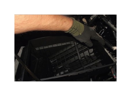
13. Disconnect the clip securing the MAF harness to the air box. Then remove the bottom portion of the factory air box by pulling up and out.
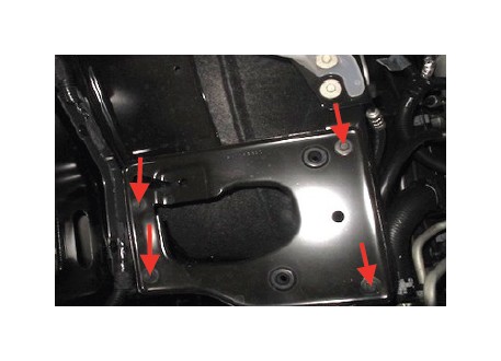
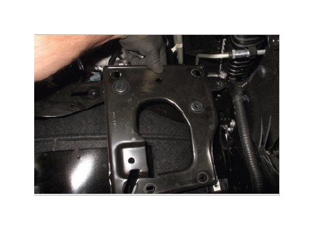
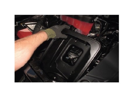
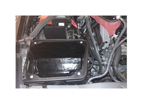
14. Remove all four bolts from the factory mounting plate then remove the factory mounting plate from the vehicle.
15. Install the Side Fender Seal (F) onto the Air Box (A) and press on firmly.
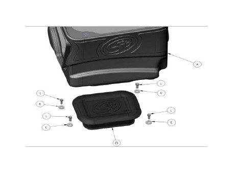
16. Determine if you want to install the Box Plug (G) onto the Air Box (A) or leave it open. See the “Air Box Plug” note on Page 5 for more information. If the Box Plug is desired, simply press the Box Plug into the box opening until it snaps into place.
17. Note: If you have vehicles equipped with HID headlights proceed to Step 18, otherwise continue with Step 17. Install the Air Box (A) and remember to properly align the fender seal to the side fender opening. Secure the air box with the M6 Bolts (L) and Washers (K). Make sure all fasteners are tightened. Go to Step 21.
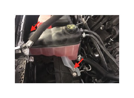
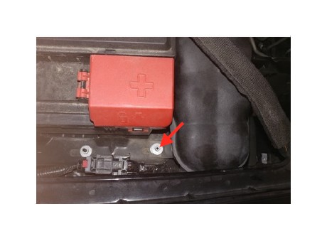
18. If you have vehicles equipped with HID headlights there is an extra step that will be needed to install the Air Box (A) due to the headlights protrudes out the back more so than the regular headlights. Use a 10mm to remove the two fasteners securing the coolant reservoir in the front and behind the battery. Set the fasteners aside they will be reused in Step 20. Set the coolant reservoir on top of the engine.
19. Install the Air Box (A) and remember to properly align the fender seal to the side fender opening.
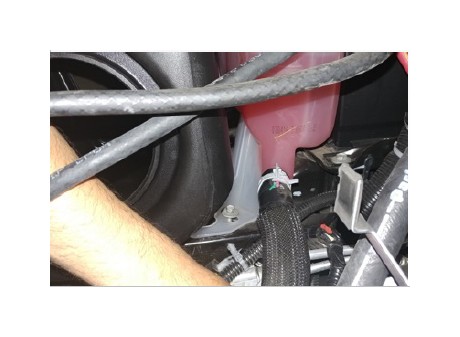
20. Before securing the Air Box (A) you will have to reinstall the coolant reservoir. Lift one side of the air box slightly and slide the coolant reservoir into position. Reinstall the fasteners removed in Step 18 with a 10mm. Then secure the air box with the M6 Bolts (L) and Washers (K). Make sure all fasteners are tightened.
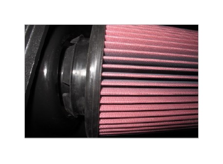
21. Install the Air Filter (E) by pressing the filter tabs through the side of the Air Box (A). The filter should lock into place when the tabs are secured.
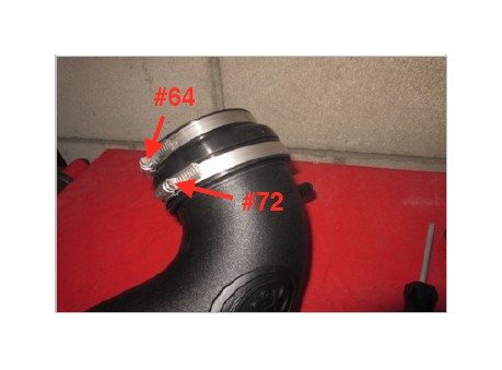
22. Install the larger side of the Coupler (C or D) onto the Air Tube (B) with the #72 and #64 Hose Clamps (U & T). Tighten the #72 Hose Clamp at the intake tube. The coupler used is dependent on the vehicle engine liter you have NOTE: (5.3L use AI1665C-00, 6.2L use AI1542C-00)
23. Use the provided Hardware (O) to install the MAF Plate (N) and Gasket (M) onto the Air Tube (B). The arrow on the plate should line up with the arrow on the tube.
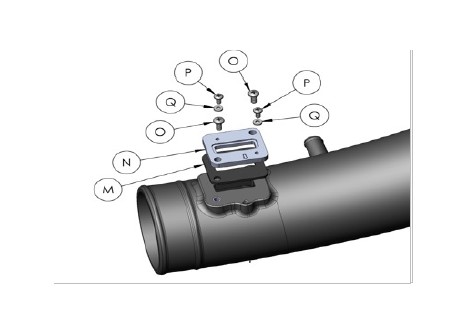
24. Use the provided Hardware (P&Q) to install the MAF sensor onto the MAF Plate.
25. Install the #64 Hose Clamp (T) loosely over the Air Filter (E) push the Intake Tube (B) into the filter then slide the intake tube and coupler onto the throttle body. Once positioned properly tighten all hose clamps.
26. Connect the MAF harness to the MAF sensor. Make sure the red locking latch is secure.
27. Use the provided Hose Clamps (V) and Crankcase Hoses (J) to install onto the valve cover ’s intake tube. Once the hoses are secure to the Intake Tube, install onto the vehicle and tighten down with the provided Hose Clamps (V).
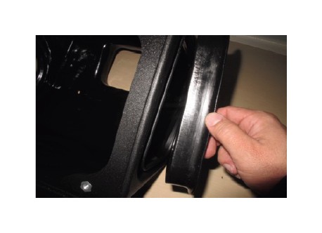
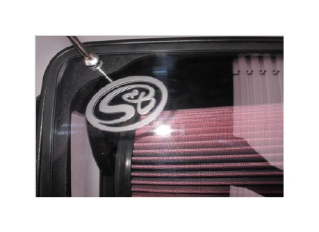
28. Remove the protective covering on the Clear Lid (H) and install the Lid Bumper (I).
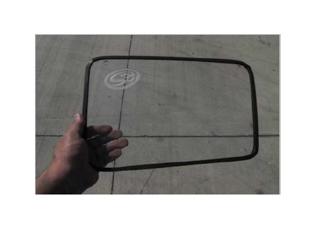
29. Install the Clear Lid (H) using the provided Hardware (R&S).
30. Reinstall the front crossbar and push pins on the plastic liner.
31. Reconnect the negative terminal on both batteries. Inspect your installation, make sure the kit is properly positioned and all fasteners are secure. Affix the ID label near the intake kit. The installation is now complete.
AIR BOX PLUG TESTING
Stock air boxes are a significant contributor to poor air flow which is why S&B designs custom air boxes with secondary and/or enlarged openings. With that said, S&B recognizes the benefits of cooler air, so we have included a plug to seal off the opening if so desired. For optimal performance, we recommend that the intake be used without the end cap except in conditions of extreme heat.
PERFORMANCE TESTING
• Engage parking brake and start your engine. Listen for abnormal noises. If an air leak is detected, re-inspect hoses and connections as they may need to be repositioned and tightened.
• S&B FILTERS recommends that you keep your OE intake system in the event it is required in the future.
• In order to maintain your warranty, all connections and components must be checked periodically for alignment and for proper tension on all connections. Failure to do so may void your warranty.
• Use only S&B FILTERS cleaning and oil products to service your filter. Using any other brand oil and or cleaners on your S&B air filter may void your warranty.
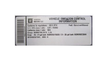
WARNING!
If your vehicle has a Vehicle Emission Control Information decal affixed to the factory airbox, a new replacement label must be obtained and installed in a readily visible position in the engine compartment in order to remain CARB compliant. Failure to do so will prevent the vehicle from passing a smog check. Replacement labels can be ordered from your local dealership. Regulations state that the VECI label shall not be affixed to any equipment which is easily detached from the vehicle. Label placement, under the hood on a painted surface is recommended.
EMISSIONS STANDARD
The California Air Resource Board (CARB) requires that an E.O. identification label be applied to the vehicle in order to pass a smog check inspection when a Performance Intake Kit has been installed. You must place the E.O. label provided on or near the intake kit after installation so that a smog check technician can easily verify the E.O. number. As of April 2009, S&B has never had a product where CARB denied an exemption request; however, the exemption process with CARB can take as long as 18 months. Check the status of the exemption process by looking up a specific part number at www.sbfilters.com. The CARB Exemption number and/or status is listed under the Product Details section for each part number. If the status shows as “Pending,” CARB has yet to issue an exemption. Products that have not been issued an EO number are street legal in most states, but may not be used on emission controlled vehicles in the state of California and are for off road use only. If you purchased your kit from S&B Filters directly, we will automatically mail you your Exemption Sticker when it is issued to us. If you purchased your kit from an authorized S&B Filters Dealer, log onto our web site and register to receive your Exemption Sticker.
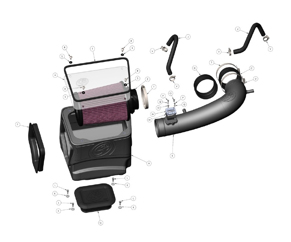
EXPLODED VIEW