FREE 1 to 3-Day Delivery on Orders $149+ Details
How to Install S & B Cold Air Intake w/ Oiled Cleanable Cotton Filter (09-13 4.8L Sierra 1500) on your GMC Sierra
Tools Required
- Ratchet and extensions
- 10mm Socket and Wrench
- 3/16” Allen Wrench
- 5/16” Nut Driver or Flat Blade Screwdriver
- Phillips Screwdriver
- 9/16” Wrench

Shop Parts in this Guide
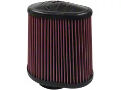
- S&B Cold Air Intake with Oiled Cleanable Cotton Filter (09-13 4.8L Sierra 1500)
- S&B Cold Air Intake with Oiled Cleanable Cotton Filter (09-13 5.3L Sierra 1500)
- S&B Cold Air Intake with Oiled Cleanable Cotton Filter (09-13 6.2L Sierra 1500)
- S&B Cold Air Intake with Oiled Cleanable Cotton Filter (09-13 6.0L Hybrid Sierra 1500)
- S&B Cold Air Intake with Oiled Cleanable Cotton Filter (2009 6.0L Sierra 1500, Excluding Hybrid)
Notes
Kit may not fit with the following Aftermarket Parts installed:
• Body Lift or Lowering Kit
• Custom Hood
• Throttle body upgrades
Before You Start
• Please read the entire product guide before proceeding.
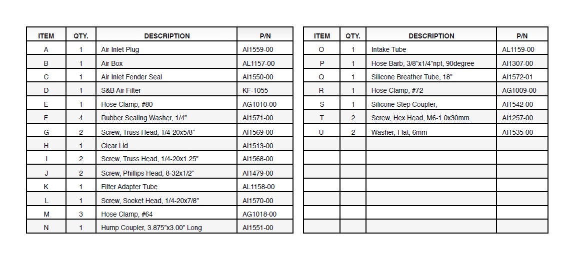
• Ensure all components listed on page 4 are present.
• If you are missing any of the components, call our customer support at (909) 947-0015.
• Do not work on your vehicle while engine is hot.
• Make sure the engine is turned off and the vehicle is in Park or
the Parking Brake is set.
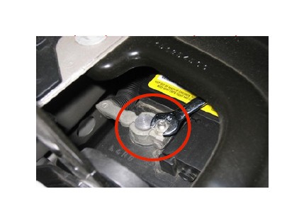
1. With the ignition switched off and the parking brake set, disconnect the negative battery cable on the passenger’s side. Note: Failure to disconnect the battery may cause the CEL to illuminate upon completion of the installation and subsequent operation. Do not skip this step!
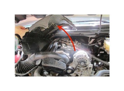
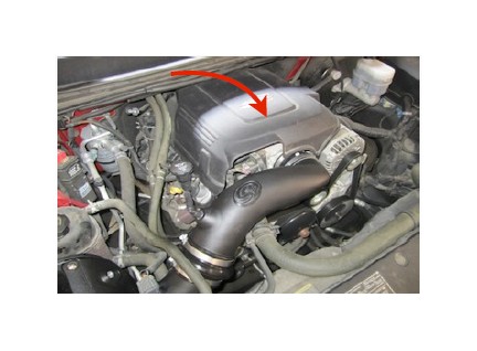
2. Remove the engine cover by lifting it up out of the grommets, then pull towards the front of the vehicle.
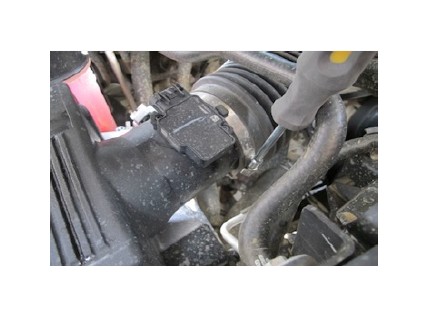
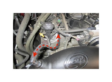
3. Disconnect the crank case vent line from the intake tube plenum by gently pulling it out.
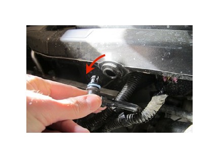
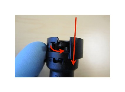
4. Disconnect the other end of the crank case vent line from the vehicle by sliding the locking tab over and pull away from the valve cover port.
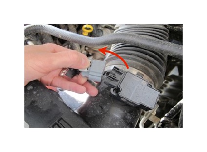
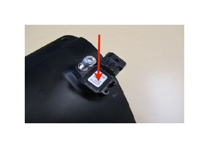
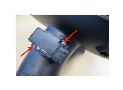
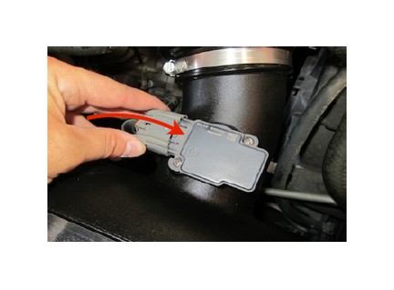
5. Disconnect the MAF sensor wiring harness from the MAF sensor. Note: If equipped, disconnect the Pressure Sensor wiring harness (located on the air cleaner lid)at this time as well.
6. Disconnect the intake tube from the throttle body.
7. Disconnect the intake tube from the air cleaner assembly. Then remove the intake from the vehicle.
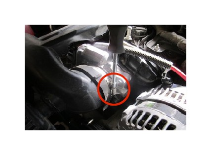
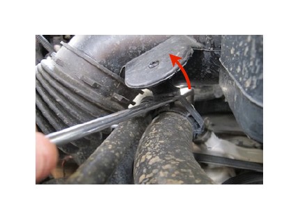
8. Using a flat blade screwdriver, remove the intake tube from the push pin located on the coolant tube. Then remove the intake from the vehicle.
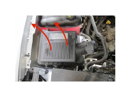
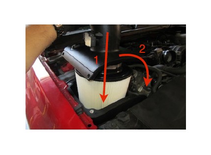
9. Remove the air cleaner box from the vehicle by carefully pulling it up out of the factory grommets.
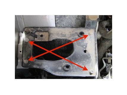
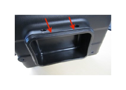
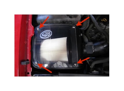
10. Using 10mm socket, remove the 4 bolts securing the air box tray. Then remove the tray from the truck. Save all 4 bolts for S&B installation.
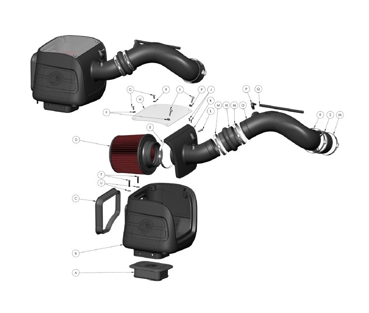
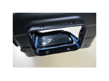
11. For those concerned about minimal engine heat; install the Air Inlet Plug (A) into the bottom of the Air Box (B) by pushing it down until the bead catches the lip as shown below. For those seeking additional air flow, set the Air Inlet Plug aside. (See page 3 for more info and test results)
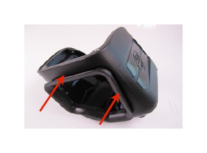
12. Install the Air Inlet Fender Seal (C) onto the lip of the Air Box (B).
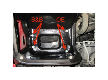
13. Install the Air box assembly using the supplied M6-1.0x10mm Screws (T) and 6mm Washers (U) in the two holes closest to the fender and the 2 longer OE screws in the remaining two holes.
14. If equipped with Pressure Sensor, Drill a 1/4” hole using the drill point located in the Filter Adapter Tube (K). Be careful only to drill through one surface (NOT all the way through the backside). Thoroughly clean the inside of the tube of all debris. Then install the pressure sensor using the 1/4-20 Socket Screw (L) and a 3/16” allen wrench.
15. Remove the MAF sensor from the OE air cleaner using the supplied T15 Torx key. Install it into the Filter Adapter Tube (K) using the supplied 8-32x1/2” Screws (J). Do not over tighten.
16. Insert the S&B Filter (D) onto the Adapter Tube (K) and secure the #80 Hose Clamp (E). Install the assembly into the Air box as shown below.
17. Install the Clear Lid (H). Secure the Lid and Filter Adapter using the supplied 1/4”-20x1-1/4” S.S. Screws (I) and Rubber Washers (F). Then use the 1/4”-20x5/8” S.S. Screws (G) and Rubber Washers (F) in the remaining two holes.
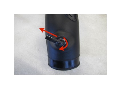
18. Install the 90degree Hose Barb (P) on to the Intake Tube (O) until it is hand tight. Then using a 9/16” wrench turn it one more rotation into position as shown.
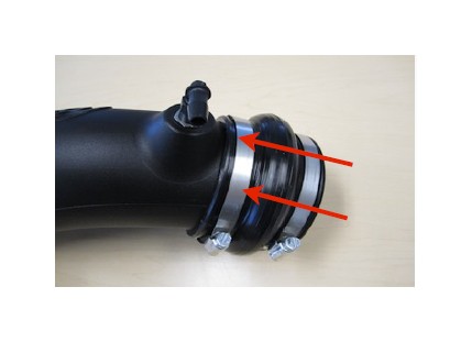
19. Place a #64 Hose clamp (M) over each end of the Hump Coupler (N). Then slide the hump coupler over the end of the Intake Tube (O).
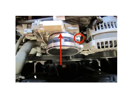
20. Secure the Silicone Step Coupler (S) to the throttle body using a #64 Hose Clamp (M). Place the #72 Hose Clamp (R) around the top of the Silicone coupler.
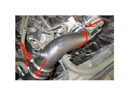
21. Insert the Intake tube assembly into the Silicone Coupler, then slide the Hump Coupler over the Adapter Tube. Tighten all hose clamps when you are satisfied with the positioning.
22. Push the Silicone Breather Hose (Q) over the Hose Barb (P) on the Intake tube. Then push the other end onto the valve cover vent line. Trim hose to desired fit if necessary. Hose should not be resting on other parts.
23. Reconnect the MAF sensor wiring harness (and Pressure Sensor if equipped).
24. Re-install the engine cover. Inspect your installation, make sure the kit is properly positioned and all fasteners are secure.
25. Reconnect the battery.
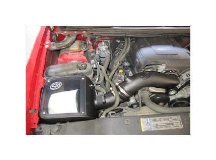
The installation is now complete.
Performance Testing
• Engage parking brake and start your engine. Listen for abnormal noises. If an air leak is detected, re-inspect hoses and connections as they may need to be repositioned and
tightened.
• S&B FILTERS recommends that you keep your OE intake system in the event it is required in the future.
• In order to maintain your warranty, all connections and components must be checked periodically for alignment and for proper tension on all connections. Failure to do so
may void your warranty.
• Use only S&B FILTERS cleaning and oil products to service your filter. Using any other brand oil and or cleaners on your S&B air filter may void your warranty.
Warning!
If your vehicle has a Vehicle Emission Control Information decal affixed to the factory airbox, a new replacement label must be obtained and installed in a readily visible position in the engine compartment in order to remain CARB compliant. Failure to do so will prevent the vehicle from passing a smog check. Replacement labels can be ordered from your local dealership. Regulations state that the VECI label shall not be affixed to any equipment which is easily detached from the vehicle. Label placement, under the hood on a painted surface is recommended.
Air Box End Cap Testing
Stock air boxes are a significant contributor to poor air flow which is why S&B designs custom air boxes with secondary and/or enlarged openings. With that said, S&B recognizes the benefits of cooler air, so we have included a plug to seal off the opening if so desired. For optimal performance, we recommend that the intake be used without the end cap except in conditions of extreme heat.
Exploded View