FREE 1 to 3-Day Delivery on Orders $149+ Details
How to Install Rough Country 7.5 in. Suspension Lift Kit w/ Shocks on your Sierra
Installation Time
1 days
Tools Required
- Floor Jack /Jack Stands
- 8mm Allen Socket
- 10mm socket /wrench
- 11mm socket /wrench
- 13 mm socket/wrench
- 15mm socket / wrench
- 17mm socket/wrench
- 18mm socket /wrench
- 21mm socket /wrench
- 22mm socket /wrench
- 24mm socket /wrench
- 19mm socket /wrench
- 35mm socket
- 9/16 socket /wrench
- Torsion bar Tool
- Reciprocating Saw
- Drill
- 11/16” Drill Bit
- Hand Grinder
- Thread Locker

Shop Parts in this Guide
FRONT INSTALLATION
1. Park the vehicle on a level surface and chock the rear wheels.
2. Jack up the front of the vehicle. Place jack stands under the frame rails and lower onto jack stands letting the front suspension hang.
3. Remove the tires and wheels. Remove the upper and lower factory skid plates using a 15mm wrench. Retain factory hardware and front skid plate for reuse.
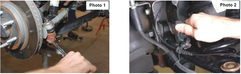
4. Using a 21mm wrench, remove the tie-rod nut as shown in Photo 1. Strike the side of the mount to dislodge the tie rod end. Remove from the knuckle.
5. Remove the sensor wire from the plastic clip. Remove the bracket from the control arm using a 10mm wrench. See Photo 2.
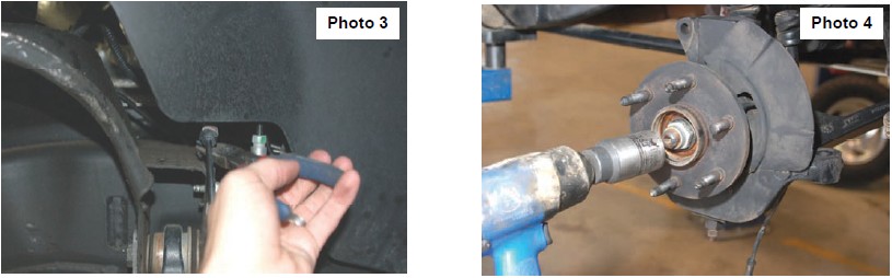
6. Remove and unplug the ABS sensor wire from the frame as shown in Photo 3 and remove the two bolts holding brake caliper to the factory knuckle using a 18mm wrench. Remove the caliper assembly from the knuckle and hang securely out of the way. Do not hang the caliper by the brake hose.
7. Remove the axle nut from the knuckle as shown in Photo 4 using a 35mm socket. Retain the hardware for reuse.
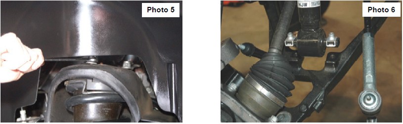
8. Using a 18mm wrench, remove the upper strut nuts as shown in Photo 5. Retain factory hardware for reuse.
9. Using a 15mm wrench, remove the 2 bolts securing the lower strut as shown in Photo 6, to the lower control arm and remove the strut from the vehicle. Remove and discard the factory lower retainer clips. New hardware will be used.
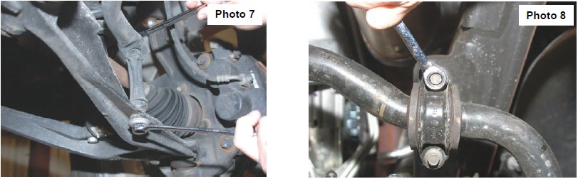
10. Remove the sway bar & end links from the lower control arm as shown in Photo 7 using a 15mm wrench.
11. Remove the sway bar from the frame as shown in Photo 8 using a 10mm wrench. Retain all hardware for reuse.
12. Using a 15mm wrench, remove the 6 axle shaft bolts from the differential and remove from the knuckle. Repeat on opposite side.
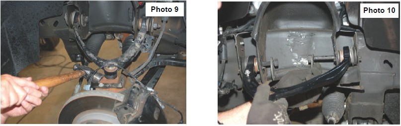
13. Remove the upper and lower ball joint from knuckle using a 18mm wrench and 24mm on the lower. Upper shown in Photo 9. Strike the knuckle as shown to dislodge the ball joint. Separate the upper control and lower control arm from the knuckle and remove the knuckle and the lower control arms from the vehicle.
14. Mark location of alignment cams on upper control arms to allow reinstallation of stock arm to the same position. Using a 21mm wrench and 21mm socket, remove the upper control arms from the vehicle. See Photo 10. Retain the hardware for reuse.
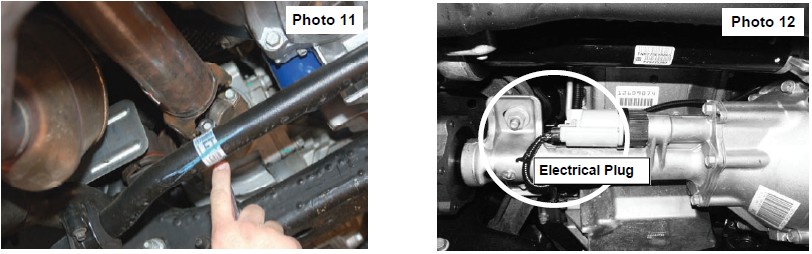
15. Make an alignment mark to show relationship between driveshaft and differential input flange. Using a 11mm wrench, remove the four drive shaft bolts. See Photo 11. Retain hardware for reuse.
16. Place a floor jack under the differential assembly to provide support for following steps.
17. Unplug the electrical connector on differential as shown in Photo 12.
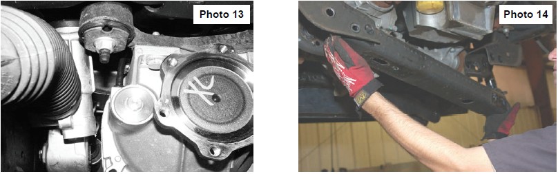
18. Unplug the differential vent hose shown in Photo 13.
19. Remove the four rear cross member bolts and remove the rear cross member brace as shown in Photo 14 using a 18mm wrench.
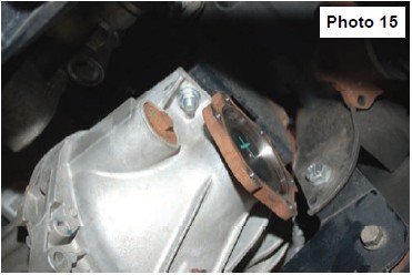
20. Using a 18mm socket remove the 4 differential bolts (2 each side) securing the differential to the frame. See Photo 15. Retain the hardware for reuse.
21. Slowly lower differential assembly to the ground.
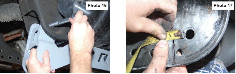
22. Install the front cross member as shown in Photo 16 with the supplied 5/8” x 4 1/2” bolts, nuts /washers. Do not tighten at this time.
23. On the drivers side rear lower control arm pocket, measure over 3/4” from the edge of the hole on the rear frame where the cross member was removed in step 10 and mark area to be cut as shown in Photo 17. Please note the area needs to be cleaned of any oil, grease and/or undercoating. These coatings can be flammable.
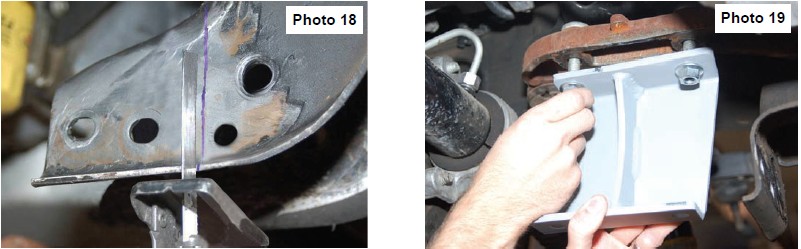
24. Cut area with reciprocating saw as shown in Photo 18 and remove. Be sure to cut all the way through front to back.
25. After the cross member has been trimmed, grind the edges smooth using a hand grinder, and apply paint to raw metal.
26. Install the Passenger differential drop bracket (open side to center of truck) with the supplied 12mm flange nuts. See Photo 19.
27. Install the Driver side differential drop bracket (open side to center of truck) with the notch at the bottom to allow clearance for the differential axle shaft flange using the supplied 12mm x 35mm bolts & washers. Do not tighten.
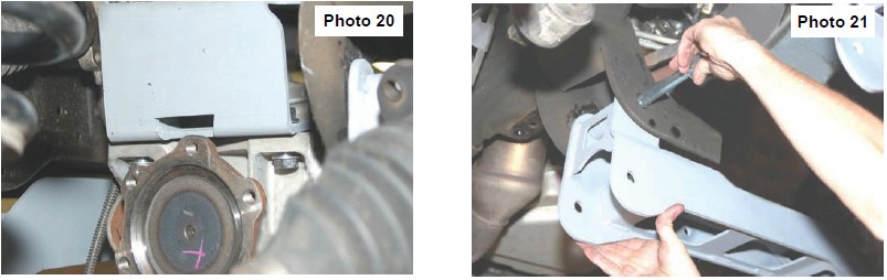
28. Raise the differential back into place and install on the drivers side drop brackets with the supplied 12mm flange nut and the factory bolts. See Photo 20.
29. Install the differential to the passenger side drop brackets with the factory nuts and the supplied 12mm x 45mm bolts & washer on the head of the bolt. The stock nuts/ large washers must be reused to make sure the differential stays located in the drop bracket.
30. Tighten the diff drop brackets (65ft. lbs) to the frame and the differential to the diff drop brackets using a 18mm wrench .
31. Install the rear cross member in the factory location using the supplied 5/8” x 5 1/2’ bolts, nuts/ washers as shown in Photo 21.
32. Reinstall the lower control arms in the cross member brackets with the factory hardware. Do not tighten at this time.
33. Tighten front and rear crossmembers at this time.
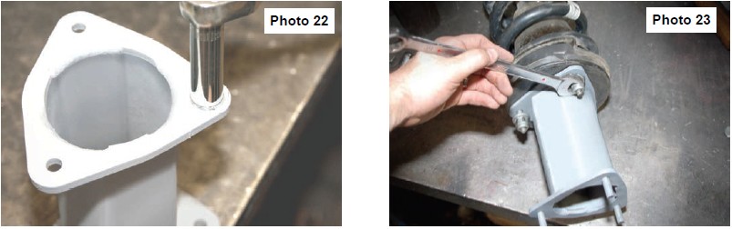
34. Using a 17mm wrench and the supplied sleeve and nut, press in the 10mm studs into the strut spacer. See Photo 22.
35. Install the strut spacer on top of the factory strut as shown in Photo 23 with the stock hardware. Tighten using a 18mm wrench.
36. Install the strut in the upper strut tower using the supplied 10mm nuts, washers & lock washers. Tighten using a 18mm wrench.
37. Install the lower part of the strut in the factory location on the lower control arm with the supplied 10mm x 55mm bolts, nuts /washers. Tighten using a 17mm wrench.
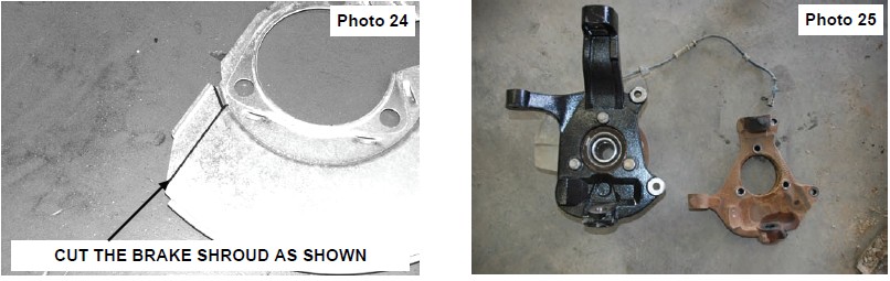
38. The brake shroud must be trimmed to allow the caliper to reinstalled, Mark the dust shroud as shown in Photo 24 and trim. Reinstall the brake caliper on the knuckle with the factory hardware and tighten.
39. On the factory knuckles, remove the bearing assembly using a 15mm wrench and install in the new knuckle. Tighten hardware. See Photo 25.
40. Install the knuckles on the lower ball joint with the factory hardware. Tighten using a 24mm wrench
41. Position the axle shafts in the knuckle and tighten the factory nut using a 35mm socket. Torque to 155 ft-lbs.
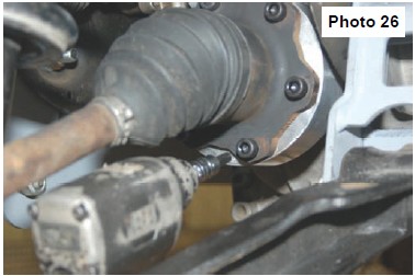
42. Install the CV axle spacer as shown in Photo 26 between the axle shaft and the differential. Secure with the supplied 10mm x 65mm allen head bolts using 8mm allen socket. Use Loctite on the bolt threads and torque to 45ft. Lbs using a crossing pattern.
43. Install upper ball joint, with the factory hardware, into the knuckle and tighten using an 18mm wrench.
44. Trim tie rod ends as per instructions on last page and install on the knuckle. Tighten using a 21mm wrench.
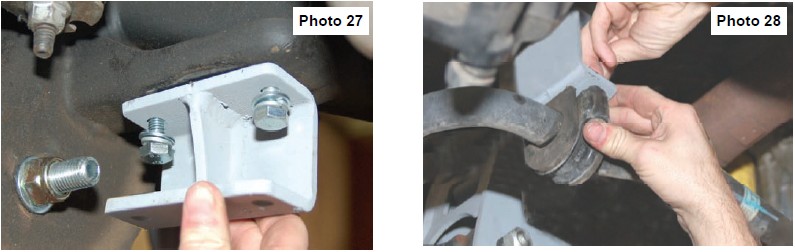
45. Install the sway bar drop brackets with the 10mm x 35mm bolts, lock washers, and flat washers using a 17mm wrench. Tighten hardware. See Photo 27.
46. Install the sway bar on the sway bar drop brackets with the stock bolts and supplied 10mm nuts & washers. Tighten using a 17mm wrench. See Photo 28.
47. Reinstall the drive shaft on the differential with the stock hardware using a 11mm wrench. Note clocking marked during disassembly.
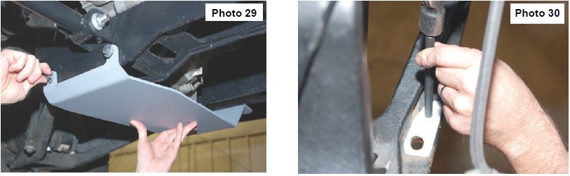
48. Install the skid plate as shown in Photo 29 with the supplied four 3/8” x 1” bolts, flat washers and lock washers on the front and rear cross member. Tighten using a 9/16 wrench.
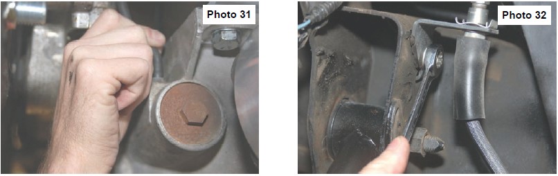
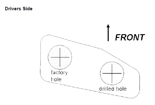
49. Using the supplied template on last page of instructions as a guide, mark and drill the lower control arm using a 11/16” drill bit to relocate the sway bar end link. See Photo 30. After drilling, install the sway bar end link with the stock hardware and tighten.
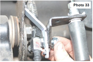
50. Slightly pull down on the diff vent hose and reinstall on the differential. See Photo 31. It may be necessary to loosen the diff vent hose from the wire loom to allow for enough slack to reconnect to the axle.
51. Reconnect the electrical connection on the axle that was removed in Step 16.
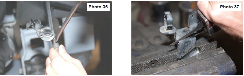
52. Remove the brake line bracket from the upper control arm mount as shown in Photo 32 using a 13mm wrench.
53. Install the supplied brake line relocation bracket on the upper control arm mount with the stock hardware. Slightly pull down on the brake line assembly and reinstall on the drop bracket with the supplied 5/16” x 3/4” bolts, nuts /washers using a 7/16 wrench. See Photo 33. Reconnect the ABS wire that was disconnected in Step 6.
54. Remove the ABS wire from the brake line clip and remove the brake line from the bracket using a flat head screw driver as shown in Photo 36 and trim as shown in Photo 37. Reinstall the modified bracket on the stock control arm with the stock hardware and reinstall the ABS wire in the clip.
55. If the optional kicker bars were purchased with this kit, install at this time per the instructions included with that kit.
56. Reinstall the factory upper skid plate with the factory hardware.
57. Install the tires and wheels. Jack up the front of the vehicle and remove the jack stands.
58. Lower the vehicle to the ground.
REAR INSTALLATION INSTRUCTIONS
1. Chock the front tires.
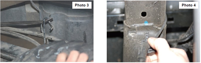
2. Before jacking up the rear of the vehicle. Remove the stock brake line bracket using a 13mm wrench, from the driver side frame rail to allow the extension bracket to be installed. Also remove the clip securing the hard line and wiring hardness to the top of the frame. See Photo 1. The stock bolts can be accessed from the side of the vehicle. Retain the stock hardware for reuse.
3. Install the brake line bracket to the new bracket with the supplied 5/16” x 3/4” bolts, nuts /washers. Reinstall the assembly in the stock location with the stock hardware using a 13mm wrench. See Photo 2.
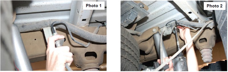
4. Remove the e-brake cable from the mount as shown in Photo 3. This will require a screw driver to bend open mounting loop.
5. Remove the ABS wire, if equipped, from the frame rail as shown in Photo 4 to allow slack in the line.
6. Jack up the rear of the vehicle and place jack stands under the frame rails. Remove tire and wheels.
7. Lightly support the differential with a floor jack .
8. Remove the stock shock absorbers using a 21mm wrench. Retain the hardware for reuse.
9. Remove the stock u-bolts and lower the axle to allow the supplied block to be installed. Discard the factory block if so equipped.
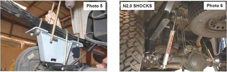
10. Install the new block with the supplied 7/16” X 3” u-bolts on the leaf spring. Do not tighten at this time. Jack up the axle to meet the new block and make sure the center pin is in the axle. Tighten 7/16” u-bolts. See Photo 5. Note short side of block goes towards front of vehicle.
11. Install the supplied u-bolts and tighten using a 22mm wrench and a crossing pattern. See Photo 5.
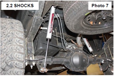
13. Install shock absorbers #658727 in the factory location tighten using a 21mm wrench. See Photo 6. Note 2.2 upgrade shocks are designed to run piston down as shown. See Photo 7
14. Using WD-40 lubricate the ABS wire and slide the rubber sleeve up to allow the wire to be reinstalled in the clip on the frame. The connector will not be reattached to the top of the frame. Reroute the lines as needed to gain sufficient slack.
15. Re-install tires and wheels.
16. Remove jack stands and lower vehicle to ground.
17. Place shock decals on shock absorbers and window decal on vehicle.
TEMPLATE FOR SWAY BAR RELOCATION
Cut out template and position template on lower control arm as shown in Step 45. Drill with a 11/16 drill bit and relocate the sway bar end links into the new location.
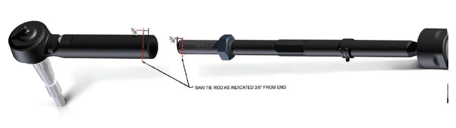
INSTRUCTIONS FOR TRIMMING TIE ROD ENDS.
1. Disassemble the tie rod from the tie rod ends
2. Measure over 3/8” and mark.
3. Cut the tie rods / tie rod sleeves as shown below to allow the vehicle to be realigned.
4. Smooth any rough edges.
5. Reassemble the cut assembly
POST INSTALLATION INSTRUCTIONS
1. Check all fasteners for proper torque. Check to ensure for adequate clearance between all rotating, mobile, fixed, and heated members. Verify clearance between exhaust and brake lines, fuel lines, fuel tank, floor boards and wiring harness. Check steering gear for clearance. Test and inspect brake system.
2. Perform steering sweep to ensure front brake hoses have adequate slack and do not contact any rotating, mobile or heated members. Inspect rear brake hoses at full extension for adequate slack. Failure to perform hose check/ replacement may result in component failure.
3. On some vehicles the front lower skirting will need to be trimmed if using certain wheel /tire combinations and with heavy offset wheels. Trim only as needed.
4. Activate four wheel drive system and check front hubs for engagement.
5. Have a qualified alignment center align the vehicle immediately. Realign to factory specifications. The following are the recommended specifications:
Caster in degrees 4.5 -1.0
Camber in degrees 0.0—.3
Toe In in degrees 0.1 -.2
Important note: For alignment purposes, please refer to the instructions above. The inner & outer tie rod ends may need to be trimmed to allow the front end alignment to be set properly. Please alert your alignment specialist of this possibility.
6. Perform head light check and adjustment to proper settings.
7. Check and retighten wheels at 50 miles and again at 500 miles.
8. All kit components must be retightened at 500 miles and then every three thousand miles after installation. Periodically check all hardware for tightness.
9. Install “Warning to Driver” decal on sun visor
Note: Installation of larger tires will require speedometer recalibration.