FREE 1 to 3-Day Delivery on Orders $149+ Details
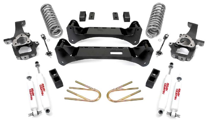
How to Install Rough Country 6 in. Suspension Lift Kit on your Ram
Installation Time
6 hours
Tools Required
- 13mm Wrench
- 13mm Socket
- 14mm Socket
- 15mm Wrench
- 15mm Socket
- 16mm Wrench
- 18mm Wrench
- 18mm Socket
- 19mm Socket
- 21mm Wrench
- 21mm Socket
- 24mm Socket
- 7/8 Deep Well Socket
- T30 Torx Socket
- 4 Ton Floor Jack
- 2 Jack Stands

Shop Parts in this Guide
FRONT INSTALLATION INSTRUCTIONS
1. The tools needed , and parts for this installation are on the front cover. Make sure you have all of the proper tools and understanding of these instructions before you proceed.
2. Place the truck on a clean level surface and set the parking brake. Chock the rear wheels and using a floor jack raise the front of the truck and support the frame rails with approved jack stands. NEVER WORK UNDER AN UNSUPPORTED VEHICLE, Using a 7/8 deep well socket remove the front wheels.
3. Remove the brake calipers from the spindle bracket using a 13 mm wrench. Using a pry bar to pry up the caliper, zip tie the caliper to the frame rail. Do not let the caliper hang from the hose. Remove the two bolts securing caliper bracket to the spindle.
4. Remove Rotor
5. Using a T30 Torx socket remove the ABS wire from the spindle as shown in Photo 1
6. Unplug the ABS wire as shown in Photo 2.
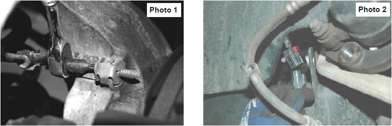
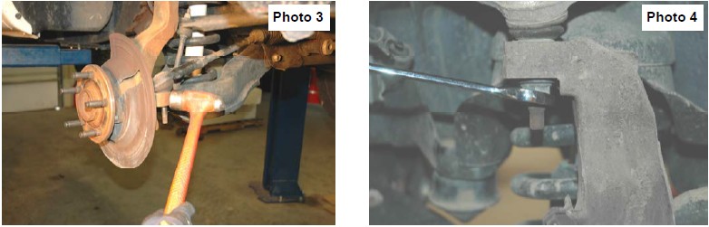
7. Using a 21 mm socket remove tie rod end from the spindle. Using a hammer lightly wrap on the spindle around the ball joint to loosen. Remove from spindle See Photo 3.
8. Using a 21 mm wrench loosen the nut on the upper control arm ball joint, but do not remove. See Photo 4.
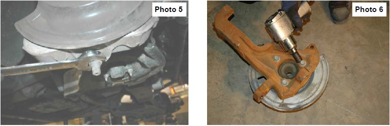
9. Using a 24 mm wrench loosen the nut on the lower control arm ball joint. Using a hammer lightly rap on the spindle around the ball joint until it breaks free from the joint. See Photo 5
10. Take nuts off of the upper and lower control arm ball joints and remove spindle.
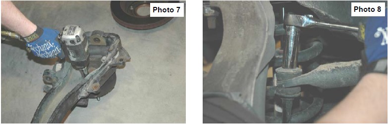
11. Turn spindle on its back side. Using a 18mm socket remove the 3 bolts holding the hub assembly and dust cover on the spindle. See Photo 6.
12. Using the 18mm socket reinstall the hub assembly and dust cover on Rough Country spindle using the 3 factory bolts. Torque to factory specs. See Photo 7.
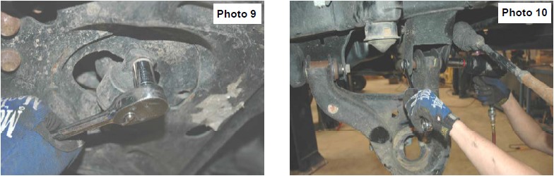
13. Using a 16mm socket remove sway bar links, the links and hardware will not be re-used. See Photo 8.
14. Remove factory shocks using a 13mm socket for the bottom and a 18mm wrench for the top. See Photo 9.
15. Remove the factory coil springs.
16. Using a 21mm wrench and a 24mm socket remove the lower control arms. Retain factory hardware for re-use. See Photo 10.
17. Hang the new Rough Country front cross member in place. Use factory hardware from lower control arms to bolt in place, do not tighten at this time.
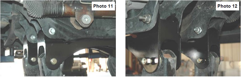
18. Hang the new Rough Country rear cross member in place. Use factory hardware from lower control arms to bolt in place, do not tighten at this time. See Photo 11.
19. Reinstall lower control arms using the 5/8”x5.5” bolts, washers, and nuts provided in 1376Bag1. Do not tighten at this time. See Photo 12.
20. Install new Rough Country coil spring part # 9293, be sure that the factory rubber isolator is still in place on the top of the coil seat. Rotate coil until it is properly seated.
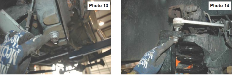
21. Place a jack stand under the lower control arm. Reinstall the new spindle on the lower control arm ball joint and install the factory nut. Torque to factory specs. See Photo 13.
22. Push the spindle up to reinstall the upper control arm ball joint. Reinstall the factory nut, torque to factory specs. See Photo 14.
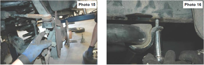
23. Reinstall rack–pinion tie rod end on the spindle. Reinstall the factory nut, torque to factory specs. See Photo 15. Reinstall ABS wires from step 5 and 6. Repeat steps 19-23 on opposite side.
24. Using a 15mm socket remover the factory sway bar bracket from the frame as shown in Photo 16. Keep factory bolts for the next step.
25. Locate sway bar bracket from 1376BOX3. Insert the (2) 3/8” x 1.25” bolts provided in the kit bag into the bracket with the hex holes. Bolt the sway bar drop bracket in the stock location using the stock bolts from the last step. Torque to factory specs.
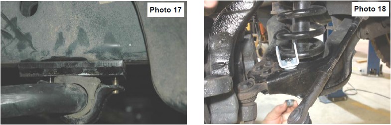
26. Align the bolts from the sway bar drop bracket with the holes in the factory bar. Using the supplied washers and nuts, tighten using a 14mm socket. Torque to factory specs. See Photo 17.
27. Locate the new sway bar link bracket and install as shown in Photo 18 on the lower control arm with the supplied 12mm x 50mm bolt, flange lock nut and thick washer under the bracket. Do not tighten at this time. Repeat on opposite side.
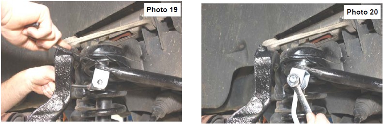
28. Install the sway bar bracket on the sway bar with the supplied 12mm x 35mm bolt and flange lock nut. See Photo 19.
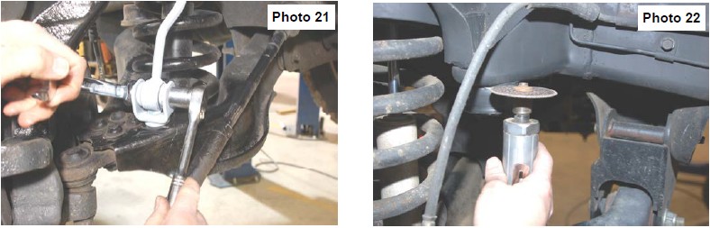
29. Install the link in the upper and lower brackets and secure with 12mm x 65mm bolts and flange lock nuts. See Photo 20 & 21. Tighten the upper and lower brackets and links using a 18mm & 19mm socket / wrench.
30. Remove the rubber bump stop from the bump stop cup and remove the mounting cup from the frame using a cutting wheel as shown in Photo 22.
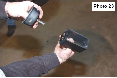
31. Reinstall the stock bump stop cup on the bump stop bracket as shown in Photo 23 using the supplied 3/8” x 1 1/4” bolts, washers/nuts.
32. Reinstall the bracket in the stock location on the frame using the supplied 3/8” 1 1/4” bolts, washers & flange lock nuts . Reinstall the stock rubber bump stop in the bump stop cup.
33. Locate shock part number 8117 hydraulic shock/ 9117 nitrogen charged shock. Using the stock bolts and a 13mm socket bolt the bottom of the shocks into the factory location. Install provided bushings on the top of the shock and tighten using a 18mm wrench. Do not over tighten, only buldge the bushings.
34. Using a 7/8” socket reinstall tires and wheels.
35. Jack up the front of the vehicle and remove the jack stands. Lower the vehicle to the floor.
36. Using a 21mm wrench and a 24mm socket tighten the and lower control arms to factory specs. Using a 24mm wrench and 24mm socket tighten the cross member to factory specs.
REAR INSTALLATION
1. Chock front wheels and jack up the rear of the vehicle. Secure with jack stands on the frame rail.
2. Place a floor jack under the rear differential on the rear axle. Using a 18mm socket and wrench, remove the stock shock absorbers, retain the stock hardware for reuse.
3. Using a 24mm socket, remove the stock u-bolts. Use the floor jack to lower the axle assembly to allow for lifted block installation.
4. Install the Rough Country block in between the leaf spring and the axle. Jack up the axle and align the pins in the blocks and axle seat. Secure with new u-bolts and torque evenly to 85 ft/lbs.
5. Locate shock part number 8112 hydraulic shock/ 9112 nitrogen charged shock and assemble poly bushings and sleeve in shock. Using a 18mm socket, and wrench, Install using factory hardware on upper and lower shock mount
6. Install the tires and wheels
7. Jack up the rear of the vehicle and remove the jack stands. Lower the vehicle to the floor.
POST INSTALLATION INSTRUCTIONS
1. Have a qualified alignment center realign front end to factory specs.
2. Install Warning to Driver decal on sun visor.
3. Re-torque all nuts, bolts, and especially u-bolts after the first 100 miles, again after another 100 miles and then check periodically thereafter.
4. All components must be retightened after 500 miles, and every three thousand miles after installation
5. Adjust headlights to proper settings.
KIT CONTENTS: