FREE 1 to 3-Day Delivery on Orders $149+ Details
How to Install MBRP Dual Intercooler Pipe - Polished Aluminum (14-17 3.0L EcoDiesel RAM 1500) on your Dodge RAM
PLEASE READ BEFORE STARTING INSTALLATION
While MBRP Inc. has made every effort to ensure that all components of this system are of superior quality and properly packaged, it is the installer's responsibility to ensure the following before removal of the factory components:
• that ALL components shown above are present.
• that ALL mating components fit together.
• that there are no damaged components.
• that the system you have purchased is appropriate for your vehicle year, model and configuration.
• that the system will not interfere with any modifications previously installed or planned.
• that you have read and understand these instructions.
If you have any questions or are uncertain about any aspect of the installation of this system to your vehicle please contact your dealer before commencing installation.
Removal of Stock Pipes:
1. Remove the engine cover.
2. Beginning with the passenger-side intercooler pipe, loosen the clamp securing the bottom hose to the intercooler outlet.
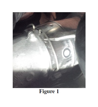
3. The upper end of the pipe is locked in place with a retaining ring. Disengage the ring by prying the top of it up, and then remove the pipe. Refer to Figure 1.
4. To remove the driver-side pipe, begin by loosening the hose clamp connecting the upper pipe to the hose attached to the plastic silencer.
5. Like the passenger-side pipe, the upper end of the driver-side pipe has a retaining ring locking it in place. Disengage the ring and remove the upper section of pipe. Refer to Figure 1.
6. Loosen the clamp securing the lower hose to the intercooler inlet and remove the hose.
7. Loosen the bolt which secures the steel band holding the plastic silencer. Once the band is loose enough, the silencer and lower tubing can be removed. Completely remove the steel band as it will no longer be used.
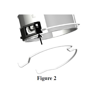
8. By prying the plastic housing out of the way, remove the stock retaining rings from both intercooler pipes. They will be reused to install the new pipes. Refer to Figure 2.
Installation of MBRP Inc. Intercooler Pipes:
NOTE: ENSURE THAT THE INSIDE OF THE INTERCOOLER PIPES ARE CLEAN BEFORE INSTALLATION.
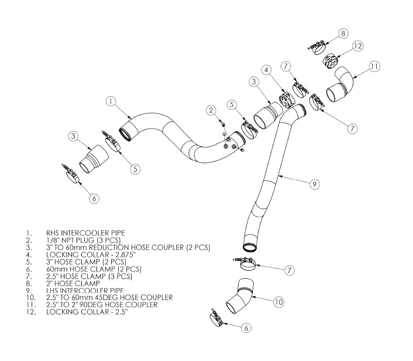
1. Install a 3” to 60mm Hose Coupler onto the intercooler outlet using a 60mm Hose Clamp. Tighten the clamp.
2. Place the RHS Intercooler Pipe into position by inserting the lower end into the 3” to 60mm Hose Coupler. Slide a 3” Hose Clamp over the hose, but do not tighten it yet.
3. Install another 3” to 60mm Hose Coupler onto the top end of the RHS Intercooler Pipe, securing it loosely using a 3” Hose Clamp.
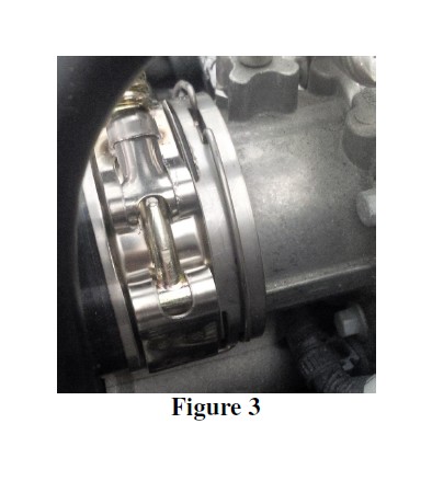
4. Prior to installing the 3” to 60mm Hose Coupler onto the engine intake, place the 2.875” Locking Collar over the hose coupler, and a 2.5” Hose Clamp over the collar. Slide the hose coupler completely onto the intake and position the collar such that the outer slots are directly over the radial groove on the intake, and the split in the collar is facing downwards. Centre the hose clamp between the narrow collar slots and tighten it. Refer to Figure 3.
5. Slide the larger of the two stock retaining rings over the 2.875” Locking Collar such that the wire tabs fall into the collar slots and into the groove around the intake. Refer to Figure 3.
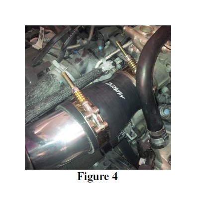
6. Position the RHS Intercooler Pipe to maximize clearances and then fully tighten the 3” Hose Clamps. Refer to Figure 4.
7. Next, install the 2.5” to 60mm 45deg Hose Coupler onto the intercooler inlet with a 60mm Hose Clamp. Do not tighten the clamp yet. Position the hose approximately in the orientation shown on the first page.
8. Remove the vent tube from the foam insulator block on top of the engine, and then remove the foam insulator block.
9. Without using clamps, place the 2.5” to 2” 90deg Hose Coupler onto the turbo outlet.
10. Install the LHS Intercooler Pipe by inserting the lower end of the pipe into the 2.5” to 60mm 45deg Hose Coupler and the upper end into the 2.5” to 2” 90deg Hose Coupler.
11. Adjust the position of the LHS Intercooler Pipe as necessary to obtain the optimal vehicle fit, then tighten the 2.5” to 60mm 45deg Hose Coupler onto the intercooler inlet with the 60mm Hose Clamp.
12. Mark/note the position of the 2.5” to 2” 90deg Hose Coupler and then remove it along with the LHS Intercooler Pipe.
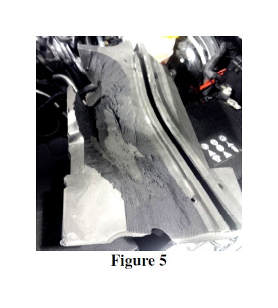
13. If you choose to reinstall the foam insulator block on top of the engine, it must be modified (trimmed) prior to installing the 2.5” to 2” 90deg Hose Coupler and the LHS Intercooler Pipe. Refer to Figure 5 to determine the approximate areas needing to be trimmed.
14. Place the LHS Intercooler Pipe into position, inserting the bottom end into the 2.5” to 60mm 45deg Hose Coupler. Slide the 2.5” Hose Clamp over the hose coupler, but do not tighten it yet.
15. Install the 2.5” to 2” 90deg Hose Coupler onto the top end of the LHS Intercooler Pipe, securing it loosely using a 2.5” Hose Clamp.
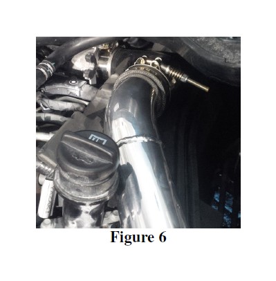
16. Prior to installing the 2.5” to 2” 90deg Hose Coupler onto the turbo outlet, place the 2.5” Locking Collar over the hose coupler, and a 2” Hose Clamp over the locking collar. Slide the hose coupler completely onto the turbo outlet and position the collar such that the outer slots are directly over the radial groove on the turbo outlet and the split in the collar is facing downwards. Centre the 2” Hose Clamp between the narrow collar slots, then tighten it while keeping the pipe in the proper position. Refer to Figure 6.
17. Slide the smaller of the two stock retaining rings over the 2.5” Locking Collar such that the wire tabs fall into the collar slots and into the groove around the turbo outlet.
18. Position the LHS Intercooler Pipe to maximize clearances and fully tighten the 2.5” Hose Clamps.
19. Replace the vent tube into the foam insulator block, or if the foam block was not reinstalled, find a suitable spot to secure it.
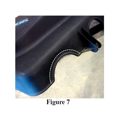
20. Trim the back of the engine cover to enlarge the circular notch enough that it is clear of the 2.5” to 2” 90deg Hose Coupler when the cover is in place. Refer to Figure 7.
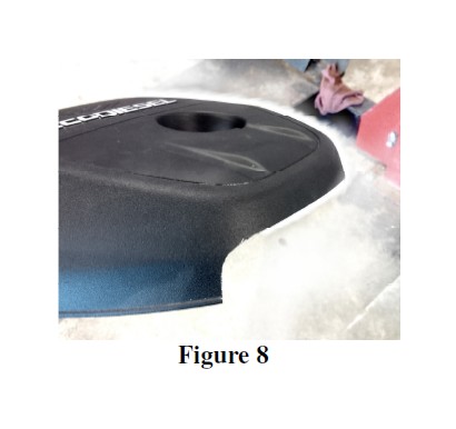
21. Trim the front of the driver side of the engine cover such that it is clear of the LHS Intercooler Pipe when the cover is in place. Refer to Figure 8.
22. Replace the cover.
23. Verify that there is adequate clearance around all hoses, wiring, covers, etc. If not, relocate or adjust.
Congratulations! You are ready to begin experiencing the improved power and driving excitement of your MBRP Inc. intercooler pipe upgrade. We know you will enjoy your purchase.