 FREE 1 to 3-Day Delivery on Orders $149+ Details
How to Install MBRP 54 in. Rigid Radius Light Bar Roof Mounting Brackets (09-15 RAM 1500) on your Dodge RAM
PLEASE READ BEFORE STARTING INSTALLATION
While MBRP Inc. has made every effort to ensure that all components of this kit are of superior quality and properly packaged, it is the installer's responsibility to ensure the following before starting:
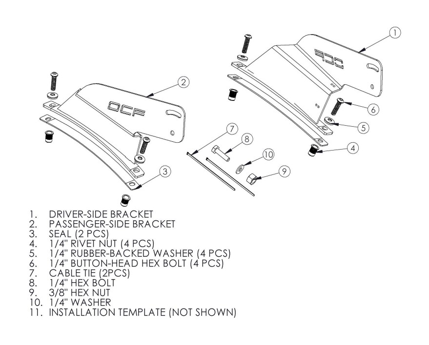
• that ALL components shown above are present.
• that ALL mating components fit together.
• that there are no damaged components.
• that the kit you have purchased is appropriate for your year and model of vehicle.
• that the kit will not interfere with any modifications previously installed or planned.
• that you have read and understand these instructions.
If you have any questions or are uncertain about any aspect of the installation of this kit on your vehicle please contact your dealer before commencing installation.
Installation of OCF Roof Light Kit
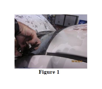
1. Pull back the driver side windshield molding. Refer to Figure 1.
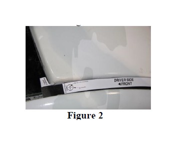
2. Cut out the Driver-Side Installation Template and position it on top of the gutter molding adjacent to the windshield. Align the “Windshield Edge” with the top of the windshield. Refer to Figure 2.
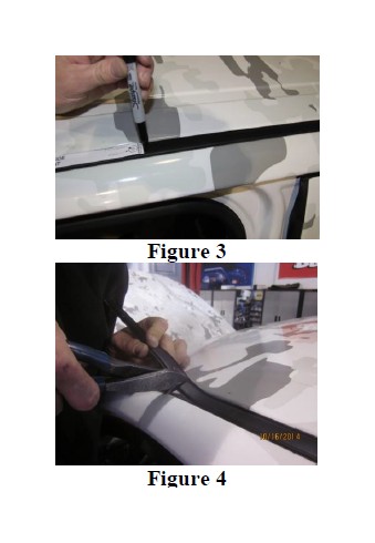
3. Mark the “gutter molding cut edge” with a marker. Refer to Figure 3.
4. Pull back the gutter molding starting at the windshield just enough to cut on the mark. Cut then push the gutter molding back down. Refer to Figure 4.
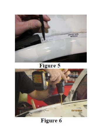
5. Tape the Driver-Side Installation Template back in place (aligned to windshield and centered in the gutter). Use a center punch and hammer to punch the front and rear drilling locations labeled on the template. Refer to Figure 5.
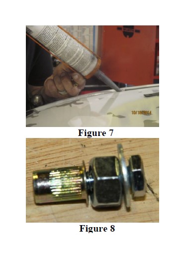
6. Remove the Driver-Side Installation Template and drill pilot holes (1/8”) on the punch marks. Slowly work up to a 3/8” hole. Use cutting lubricant if available. Refer to Figure 6.
7. File away any burrs or sharp edges to ensure the top of the Rivet Nut will sit flat and parallel with the gutter surface. Fill hole circumference with clear silicon. Refer to Figure 7.
8. Insert 1/a” Hex Bolt through 1/a” Washer then 3/8” Hex Nut and lastly screw on 1/a” Rivet Nut. Refer to Figure 8.
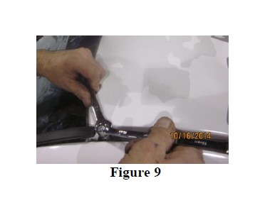
9. Apply a small amount of silicon around 1/a” Rivet Nut and insert in hole. Set the 1/a” Rivet Nut by tightening the 1/a” Hex Bolt while holding the 3/8” Hex Nut still. Do NOT let the 1/a” Rivet Nut turn. Repeat this step to set the second 1/a” Rivet Nut. Refer to Figure 9.
10. Apply clear silicon to the bottom side of: Seal, Driver Side Bracket rail and in the Rivet Nut. Position the Seal over the Rivet Nuts.
REPEAT STEPS 1-10 ON PASSENGE- SIDE.
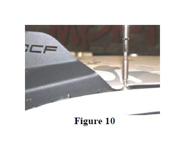
11. Using the 1/a” Button Head Hex Bolts and Rubber Backed Washers, fasten the Driver Side Bracket in place. Make sure the Rubber Backed Washer is compressed flat to make a proper seal, but so much to squeeze the rubber out. Refer to Figure 10
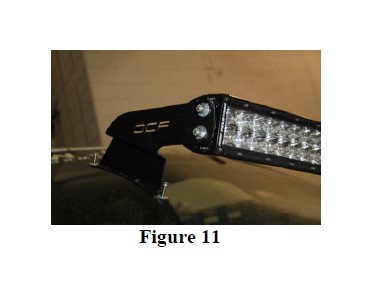
12. Fasten the Passenger-Side Bracket on the light bar. Ensure wiring is on driver side. Refer to Figure 11
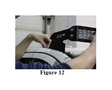
13. Install the light bar on the Driver-Side Bracket then rest the Passenger Side Bracket over the Seal. Fasten the Passenger Side Bracket in place (as per Step 9). Refer to Figure 12
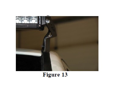
14. Run wiring along Driver-Side Bracket and secure in place with Cable Ties. Refer to Figure 13
15. Run power wire down A-pillar below molding and into engine bay (wire as per light bar instructions).
Congratulations! You’re finished!


