FREE 1 to 3-Day Delivery on Orders $149+ Details
How to Install Max Trac 3 in. Lift Spindles w/ Extended Brake Lines on your Sierra

Shop Parts in this Guide
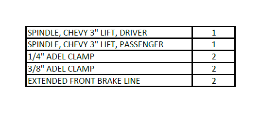
PARTS LIST
PRIOR TO INSTALLATION:
1. Factory service manual is recommended to have on hand.
2. Secure and properly block vehicle prior to beginning installation
3. Always wear safety glasses when using power tools or working under the vehicle
4. Modifications to any part will void the warranty associated with that product.
5. Jack up front of vehicle, place jack stands under frame, behind front suspension.
After removing parts from vehicle, save hardware for reinstallation
IT IS RECOMMENDED THAT YOU HAVE YOUR VEHICLE’S ALIGNMENT CHECKED WHEN INSTALLING NEW SUSPENSION PARTS. IT IS ALSO RECOMMENDED THAT YOU ADJUST YOUR HEADLIGHTS WHENEVER YOUR VEHICLE’S RIDE HEIGHT IS ALTERED.
1. Remove brake caliper bolts at the spindle, do not allow caliper to hang from brake hose. Remove retainer bolt for brake rotor, then remove rotor.
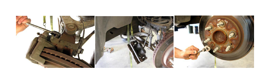
2. Open up brake hose clamp on upper control arm and remove from bracket. Unbolt brake hose bracket from upper control arm, then unbolt abs wire bracket from the spindle.
3. Remove ABS sensor from spindle and put it safely out of the way. Remove through bolt for sway bar end link and linkage.
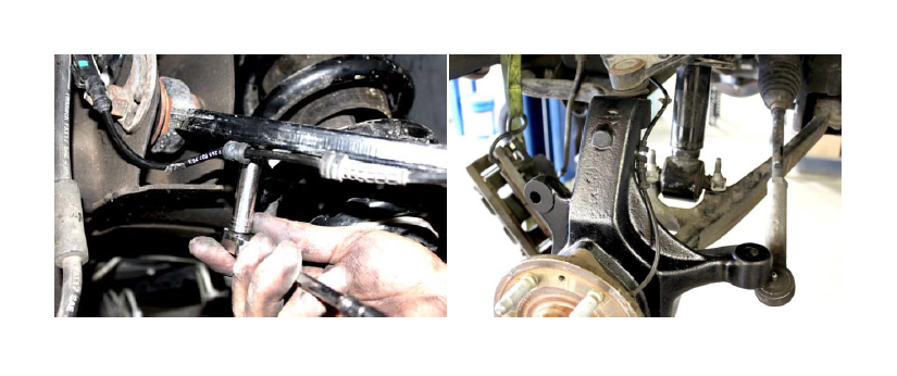
4. Unbolt unit bearing, remove and discard dust shield (will not be used). Unbolt tie rod from the spindle, then knock tie rod loose by hitting the side of the spindle, do not hit tie rod or threads!
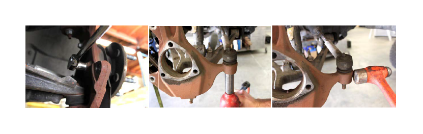
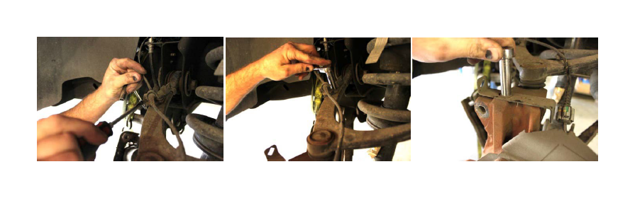
5. Loosen the upper ball joint nut, loosen the lower ball joint nut and leave the nut loose on the end of the threads, then knock the upper ball joint loose by striking the spindle (do not hit the threads!)
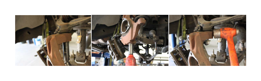
6. Support lower control arm and add pressure with a jack, then line up Maxtrac spindle with upper & lower ball joint, and loosely install nuts.
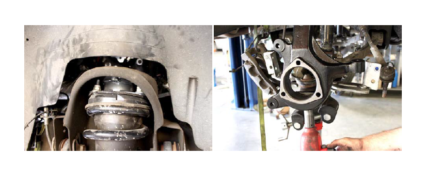
7. Tighten the upper ball joint nut, then tighten the lower ball joint nut.
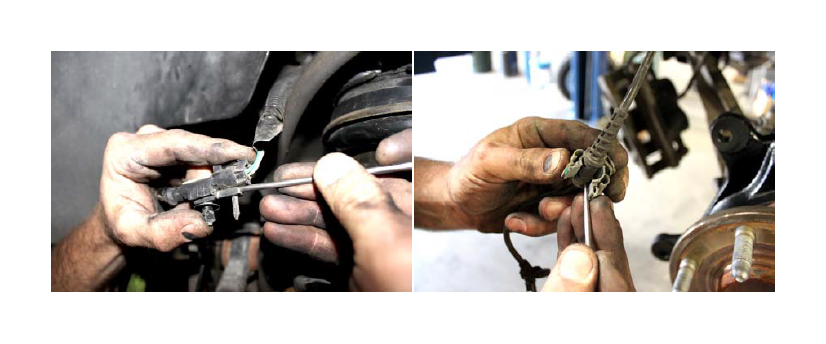
8. Remove the ABS guide clip from the rear part of the upper control arm.
9. Remove lower half of the clip from ABS plug, and then remove clip from ABS wire.
10. Use the provided Adel Clamp and factory bolt to attach ABS wire to upper control arm.
11. Then run ABS wire under upper control arm and across the front of the spindle.
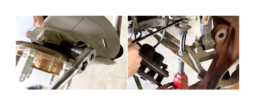
12. Attach ABS wire to Maxtrac spindle using the provided Adel Clamp and factory bolt that was previously attaching the bracket to the top of the stock spindle.
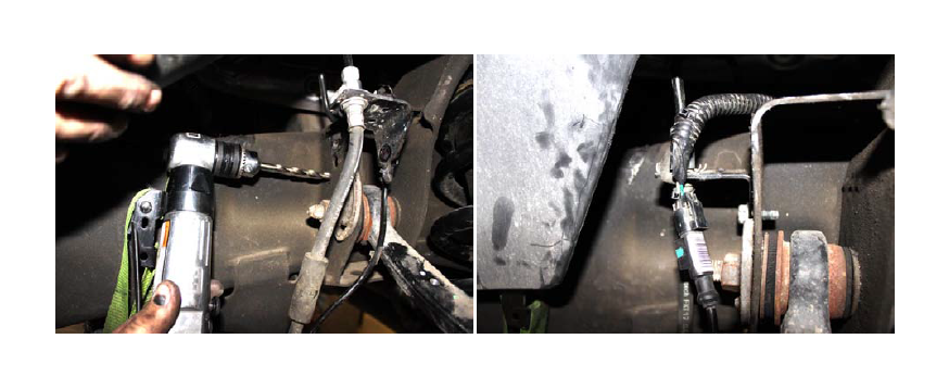
13. Unbolt brake line guide from the back side of upper control arm mount, then bend the tab on brake line bracket to a straight position.
14. Drill new hole approximately 1” below original hole, smaller than original hole, so the bolt can be self tapped in. Be sure to leave enough room for the alignment cam to fully cycle.
15. Zip tie ABS wire to the brake line.
16. Reinstall brake rotor and tighten retainer bolt, then reinstall brake caliper.
17. Carefully bend brake line elbow outward and up to allow slack in brake line.
18. Cycle spindle, at full droop, back and forth to ensure there is enough slack in the hose, and that the brake hose does not contact the lower arm or any other component.
19. Reinstall the tie rod and tighten the nut
20. Reinstall the sway bar end links and tighten.
ALIGN VEHICLE AS SOON AS POSSIBLE
RETORQUE ALL FASTENERS AFTER 50 MILES, AND THEN AGAIN EVERY 1000 MILES.