FREE 1 to 3-Day Delivery on Orders $149+ Details
How to Install K&N Brute Force Cold Air Intake - Black on your Silverado
Tools Required
- Ratchet
- 8, 10, and 19 mm Sockets
- Extension
- T15 Torx
- #2.5 & 3 Allen
- Drill
- 1/4 Drill Bit

Shop Parts in this Guide
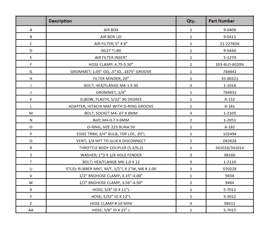
PARTS LIST
Read and understand these instructions BEFORE attempting to install this product. Failure to follow installation instructions and not using the provided hardware may damage the intake tube, throttle body and engine.
1. Preparing Vehicle
a. Make sure vehicle is parked on level surface.
b. Set the parking brake.
c. If engine has run in the past two hours, let it cool down.
d. Disconnect negative battery terminal.
e. Do not discard stock components after removal of the factory system.
f. Open the air intake kit package and make sure all parts are included.
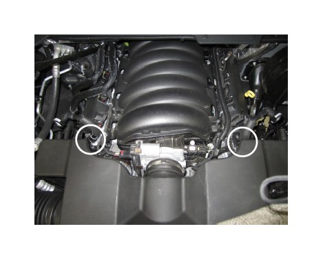
2. Removal of stock system
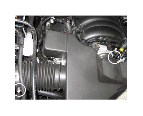
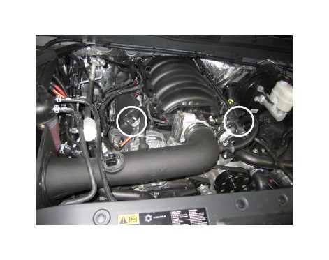
a. Remove both crankcase vent hoses by squeezing the white clip at the valve cover breather port.
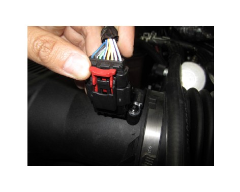
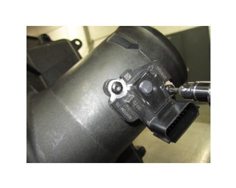
b. Pull up on the red locking clip, then depress down on the black tab while removing the mass air sensor connector.
c. Loosen the hose clamps on the air box and the throttle body. Then pull the resonator box out of the vehicle.
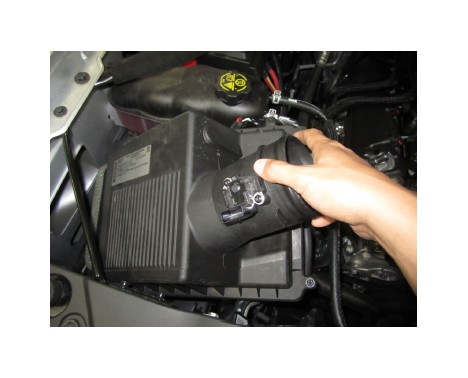
d. Gently pull up on the air box to disengage it from the rubber grommets and remove from engine compart-ment.
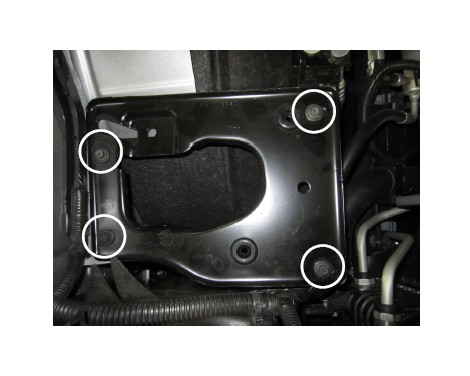
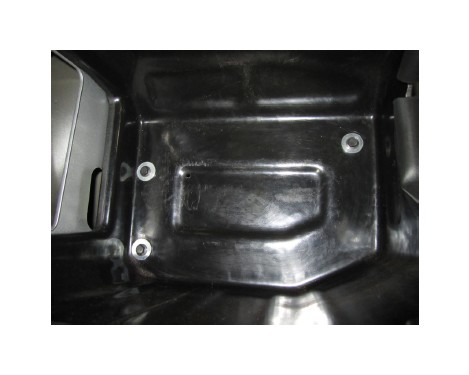
e. Loosen and remove the four M6 bolts. Then, remove the air box plate from the vehicle. These will not be re-used. Note: Do not discard the plate or hardware.
f. Remove the two M4 torx bolts with a T15 bit and slide the mass air sensor out of the tube. Note: Be very care-ful with the sensor. This will be re-installed in step 3c
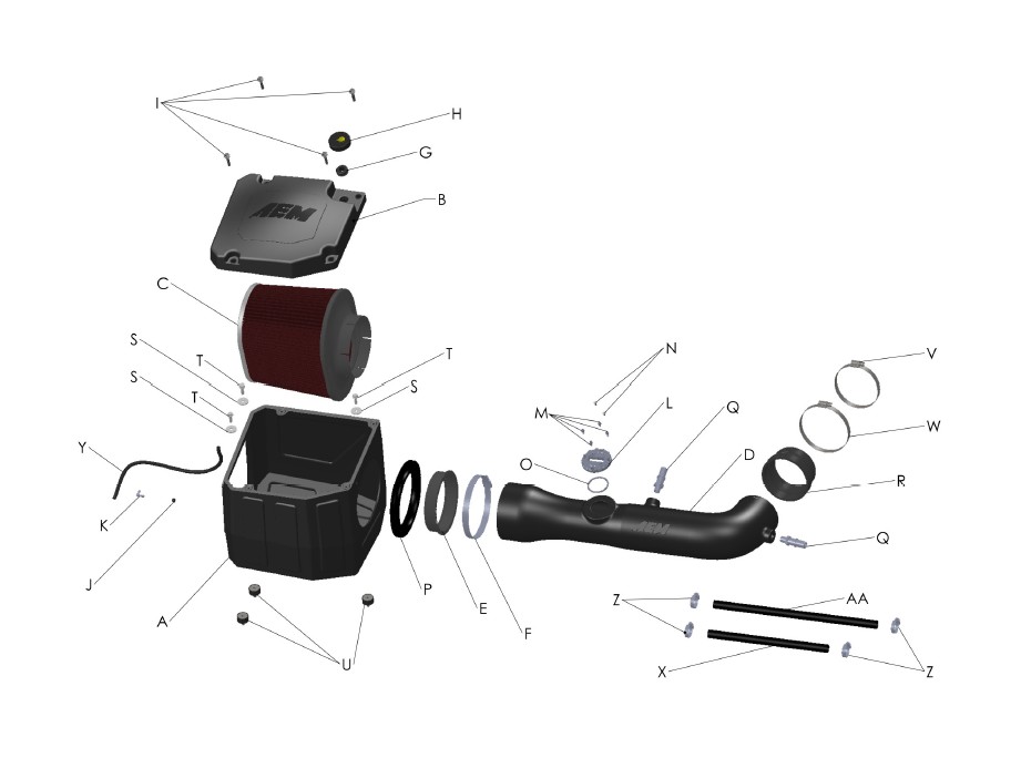
3. Installation of AEM® intake system.
a. When installing the intake system, do not completely tighten the hose clamps or mounting hardware until instructed to do so.
a. Install the provided O-ring into the mass air sensor adapter.
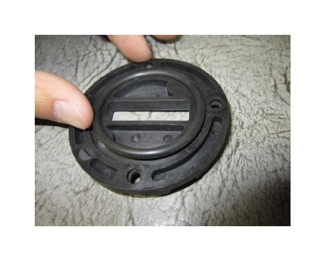
b. Install the mass air sensor adapter onto the tube with the provided M4 allen bolts.
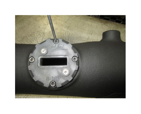
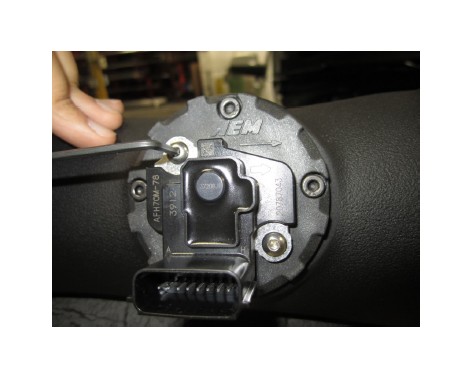
c. Install the mass air sensor into the mass air sensor adapter that has already been attached to the AEM intake tube with the provided M4 allen’s. Note: Be very careful with the mass air sensor.
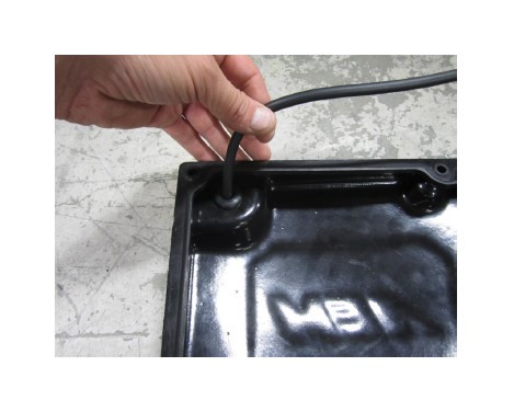
d. Install the two vent hose fittings into the tube. Note: Hand tighten, then add a quarter turn with a wrench.
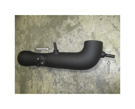
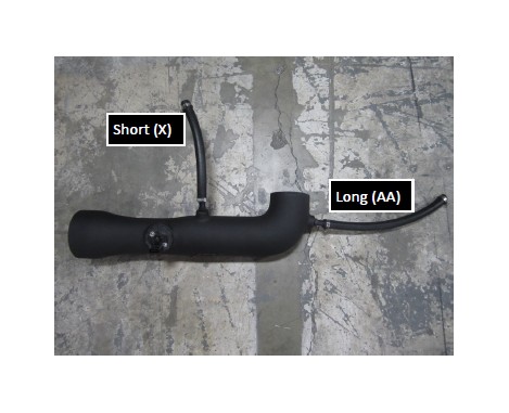
e. Slide the two provided vent hoses and four clamps onto the vent fittings and tighten. The shorter hose will go on the left vent, and the longer hose will go on the right vent.
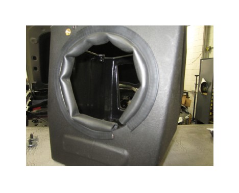
f. Install the edge trim onto the AEM air box, trim off excess if necessary.
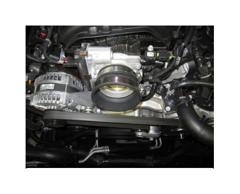
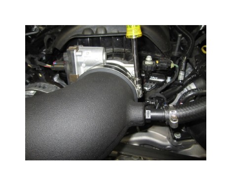
g. Install the throttle body coupler with hose clamps 5.3L use p/n 341018 and #56; 6.2L use p/n 341014 and #64. Do not tighten clamps at this point.
h. Install the three provided bushings and mount them into the inner right side fender.
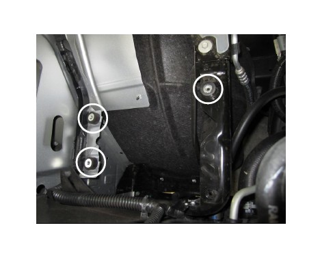
i. Insert the AEM air box over the previously installed bushing mounts. Use the provided M6 bolts and wash-ers to secure air box to the bushing mounts.
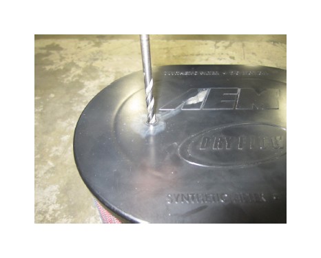
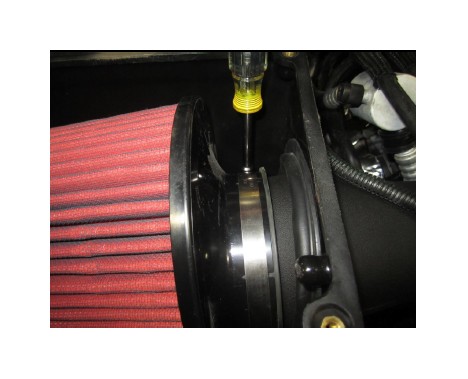
j. Drill a 1/4” diameter hole in the plastic cap of the AEM air filter as shown above. Note: Clean out all plastic shavings from the inside of the filter.
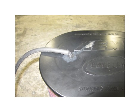
k. Install the small grommet (784631) into the drilled hole, and then install the 5/32” plastic elbow port (8- 152) into the grommet. Install the 5/32” air hose (5- 3012) onto the elbow port as show.
l. Install the air filter insert into the AEM air filter and place the filter in the AEM air box.
m. Install the assembled AEM tube into the AEM air box first then insert it into the throttle body coupler. Then slide the two vent fitting hoses over the valve cover breather ports and tighten those hose clamps.
n. Slide the filter onto the tube and tighten the hose clamp.
o. Tighten both of the intake tube to throttle body coupler hose clamps.
p. Install the provided grommet into the AEM air box lid. Then insert the filter minder gauge into the grom-met.
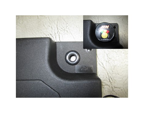
q. Install the 5/32” hose from the air filter to the filter minder gauge installed in step 3p.
r. Install the AEM lid onto the air box and tighten the four provided M6 bolts.
s. Reconnect the mass air sensor plug back into the mass air sensor, then push down on the red locking tab.

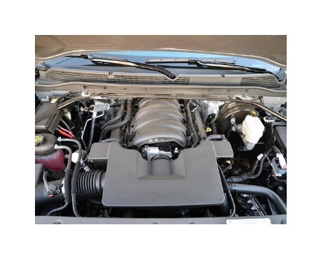
Stock intake system Installed
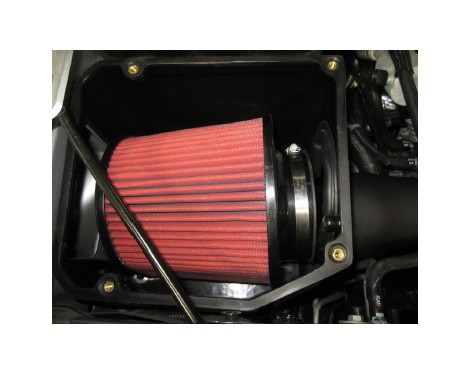
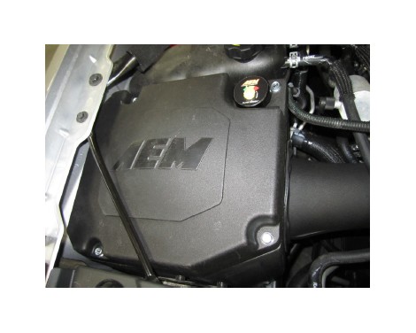
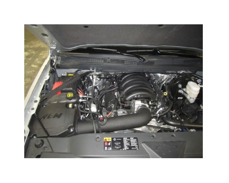
AEM intake system installed
4. Reassemble Vehicle
a. Position the inlet tube for the best fitment. Be sure that the tube or any other components do not contact any part of the vehicle. Tighten the rubber mounts, all bolts, and hose clamps.
b. Check for proper hood clearance. Re-adjust tubes if necessary and re-tighten them.
c. Inspect the engine bay for any loose tools and check that all fasteners that were moved or removed are properly tightened.
d. Reconnect negative battery terminal and start engine. Let the vehicle idle for 3 minutes. Perform a final inspection before driving the vehicle.
5. CARB Sticker Placement
a. The C.A.R.B. exemption sticker, (attached), must be visible under the hood so than an emissions inspector can see it when the vehicle is required to be tested for emissions. California requires testing every two years, other states may vary.
6. Service and Maintenance
a. AEM Induction Systems requires cleaning the intake system’s air filter element every 100,000 miles. When used in dusty or off-road environments, our filters will require cleaning more often. We recommend that you visually inspect your filter once every 25,000 miles to determine if the screen is still visible. When the screen is no longer visible some place on the filter element, it is time to clean it. To clean, purchase our Synthetic air filter cleaner, part number 1-1000 and follow the easy instructions.
b. Use window cleaner to clean your powder coated AEM intake tube. NOTE: DO NOT USE aluminum polish on powder coated AEM intake tubes.
Note: Most General Motors trucks (including Chevrolet) have the Vehicle Emissions Certification Information (VECI) label affixed to the air filter box. In order to be compliant with California emissions laws, the label MUST remain in the engine compartment. If the Vehicle Emission Control Information label is removed during modification, a new replacement label must be obtained and installed in a readily visible position in the engine compartment. The label shall not be affixed to any equipment which is easily detached from the vehicle. We recommend that the label is affixed to the underside of the hood adjacent to the hood latch. The label is Vehicle Identification Number dependent and can be ordered from the vehi-cle dealership. In order to receive the proper decal please bring your VIN with you. Failure to have the VECI under the hood may result in failure of a pre-registration smog test.