FREE 1 to 3-Day Delivery on Orders $149+ Details
How to Install SLP 1900 TVS 450 HP Supercharger on your Sierra
SAFETY PRECAUTIONS
STOP! CAREFULLY READ THE IMPORTANT SAFETY PRECAUTIONS AND WARNINGS BEFORE PROCEEDING WITH THE INSTALLATION!
Appropriate disassembly, assembly methods and procedures are essential to ensure the personal safety of the individual performing the kit installation. Improper installation due to the failure to correctly follow these instructions could cause personal injury or death. Read each step of the installation manual carefully before starting the installation.
Always wear safety glasses for eye protection.
Place the ignition switch in the OFF position.
Always apply the parking brake when working on the vehicle.
Block the front and rear tire surfaces to prevent unexpected vehicle movement.
Operate the engine only in well-ventilated areas to avoid exposure to carbon monoxide.
Do not smoke or use flammable items near or around the fuel system.
Use chemicals and cleaners only in well-ventilated areas.
Batteries can produce explosive hydrogen gas, which can cause personal injury. Do not
allow flames, sparks or flammable sources to come near the battery.
Keep hands and any other objects away from the radiator fan blades.
Keep yourself and your clothing away from moving parts when the engine is running.
Do not wear loose clothing or jewelry that can be caught in rotating or moving parts.
WARNING: SLP Recommends allowing the vehicle to cool (not running) for five hours before beginning installation.
WARNING: To avoid the chance of electrical shock or damage to your vehicle’s electrical system, disconnect both the negative and positive batter leads (in that order) at the battery.
STOCK DISASSEMBLY
The following section will guide you through the disassembly of the stock components. Special care should be taken to label fasteners and parts that are taken off during this procedure since many will be reused:
1. Cover both fenders with fender covers to protect the vehicle finish.
2. Disconnect the (-) negative & ( ) positive connections to the battery.
3. Lift up on the front of the engine cover and pull it towards you to remove it from the engine bay.
4. Loosen the worm drive clamp that holds the clean air tube to the MAF (mass airflow) sensor and the clamp that holds the clean air tube to the throttle body. Remove the PCV (positive crankcase ventilation) line from the front of the passenger side valve cover. Remove clean air tube from vehicle.
5. Use a 15mm socket to rotate the tensioner clockwise and remove the belt from engine.
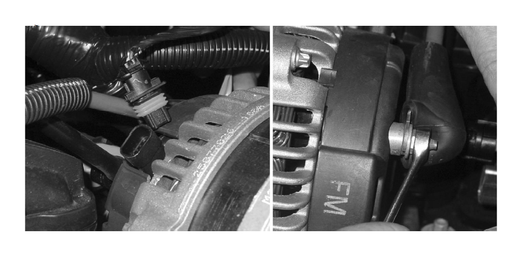
6. Disconnect the alternator harness and the B cable from the alternator. Remove the alternator from the engine.
7. Disconnect the MAP (manifold absolute pressure) sensor, ETC (electronic throttle control), VMV (vapor management valve also known as EVAP solenoid) and the fuel injectors.
8. Use a 10mm socket to remove the 3 bolts and 1 nut fastening the harness retention pieces to the intake manifold.
9. Remove the PCV line from the top of the intake manifold and the rear of the driver side valve cover.
10. Disconnect the fuel line from the driver side fuel rail and both VMV lines from the VMV.
11. Disconnect the brake booster hose at the fitting on the brake booster.
12. Loosen and remove the (10) M6 bolts that fasten the intake to the cylinder heads using an 8mm socket.
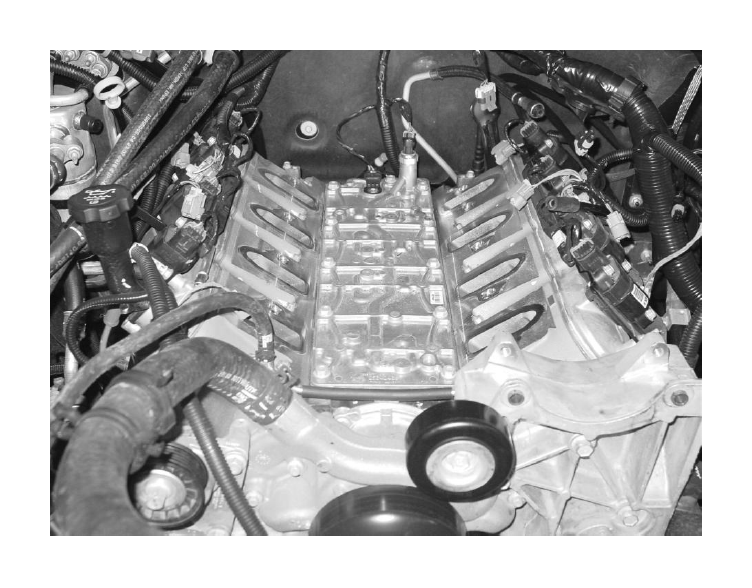
13. Remove the intake manifold and clean the intake mounting surfaces. Put tape over the intake ports to prevent debris from entering the engine.
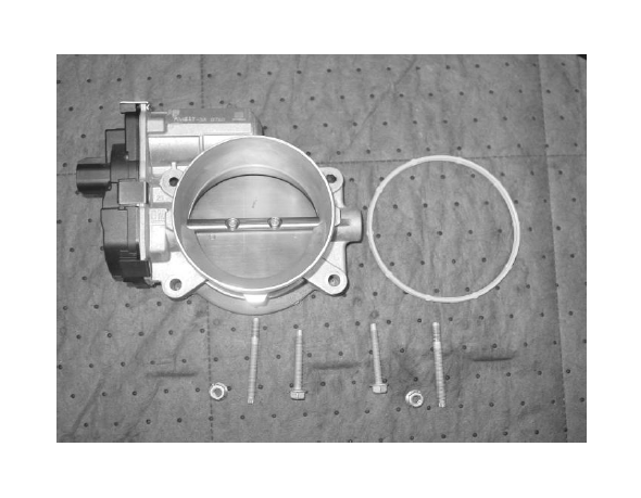
14. Remove the throttle body, the 2 (two) throttle body-mounting studs and throttle body gasket from the stock intake manifold.
The following section will guide you through the required modifications of existing components and build up of the assemblies used to complete the installation.
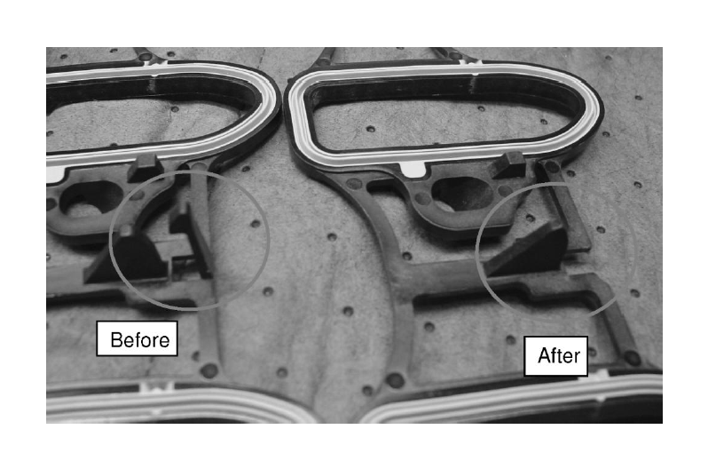
Intake Gasket Modification
1. Break the middle locking tab off of the new gaskets by bending it back and forth.
VMV Modification
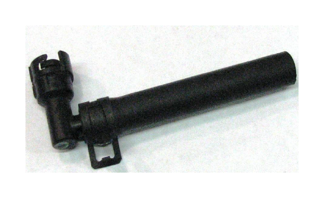
1. Using a knife, carefully cut tubing to remove a 90 degree SAE fitting from the stock VMV line.
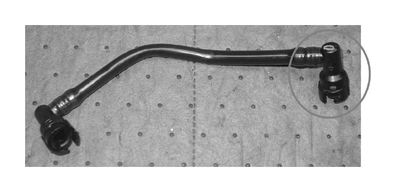
2. Use (1) 3/8” constant tension clamp to secure the supplied VMV line to the 90 deg fitting.
Wiring Harness Modification
The following details the modifications to the factory engine harness which are necessary to complete the installation of this kit. These modifications should be done without removing the harness from the engine as it will be easier to verify final locations of the break out points. Extreme care must be taken to insure that wiring and/or insulation is not accidentally damaged while removing the convoluted tubing or harness wrap. All the convoluted tubing and various clips that are removed while making these changes are intended to be reinstalled in the same place unless otherwise noted.
1. Make a note of the locations of the harness retaining clips and breakout points. Carefully cut the harness wrap off the harness at the rear of the engine from the first Y junction on the driver side to where the convoluted tubing starts on the harness with the MAP sensor breakout.
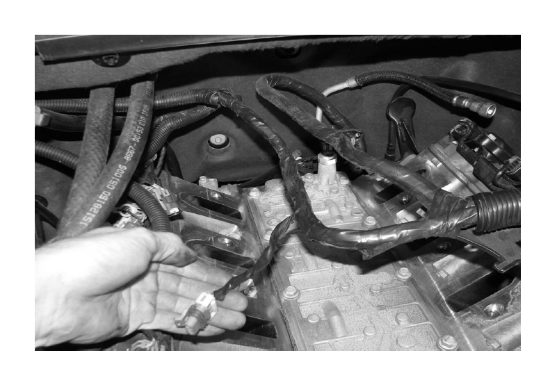
2. Locate the MAP sensor connector and the tan with black tracer wire. Cut the 4 wires (3 MAP and 1 tan) 9 inches from the Y junction.
3. Seal the passenger side of the cut tan wire with a piece of heat shrink provided. Place the piece of shrink tube halfway onto the end and heat with a heat gun until it stops shrinking and sealant flows out from the open end of the tubing.
4. Splice in the TMAP extension harness to the (4) cut wires. Shrink wrap and solder these conenctions, connect the orange wire to the Pin 1 pigtail, tan w/black tracer to Pin 2, grey to Pin 3 and green to Pin 4.
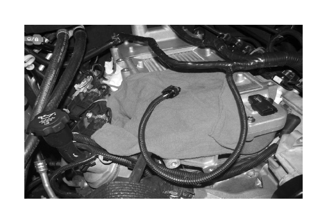
5. Cover TMAP extension harness with supplied split loom convolute. Wrap the rest of the harness with tape.
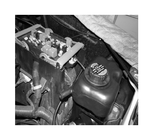
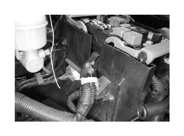
Intercooler Reservoir & Pump Bracket (Use photos on this Page to aid in steps below)
1. Using the I/C Pump Bracket and (1) M6 x 1.0 x 18.5 bolt, mount the pump to the Degas Bottle Bracket. Torque to 8 – 12 Nm.
2. Mount the relay of the I/C Wiring Harness to the bracket using (1) M6 x 1.0 x 18.5mm bolt. Torque to 8 – 12 Nm.
3. Mount the Reservoir to the bracket using (2) M6 bolts and (1) M6 cap screw with an M6 washer. Torque to 8 – 12 Nm.
4. Use the formed hose to connect the outlet of the reservoir with the inlet of the pump. Use (2) constant tension clamps to secure it in place.
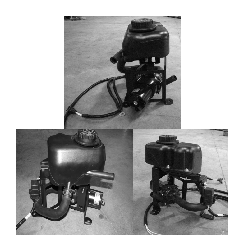
5. Connect the I/C Pump plug on the wiring harness to the I/C Pump.
Fuel Rail and Injectors
1. Lube the fuel injector o-rings with 5W30 engine oil. Install the fuel rail and injectors into the intake manifold. Once the fuel injectors are fully seated, secure the fuel rail to the intake manifold using the (4) stock fuel rail bolts. Torque to 8 – 12 Nm.
2. Orient the new fuel injectors to match the orientation of the stock fuel injectors.
3. Install the TMAP sensor using the flanged bolt provided in the same bag as the injectors are in.
Intercooler Reservoir Assembly Mounting
1. Install the reservoir assembly in the spare battery tray by reusing the hardware that holds the tray in place. Make sure not to pinch or crush any of the wiring. Torque the fasteners to 8 – 12 Nm.
4. Connect the short lead from the wiring harness to the spare M6 post on the fuse block. Use (1) M6 nut from the stock intake assembly and torque to 8 – 12 Nm.
5. Run the remaining lead in between the fuse box and the fender to the rear of the truck. Connect the eyelet to the grounding post.
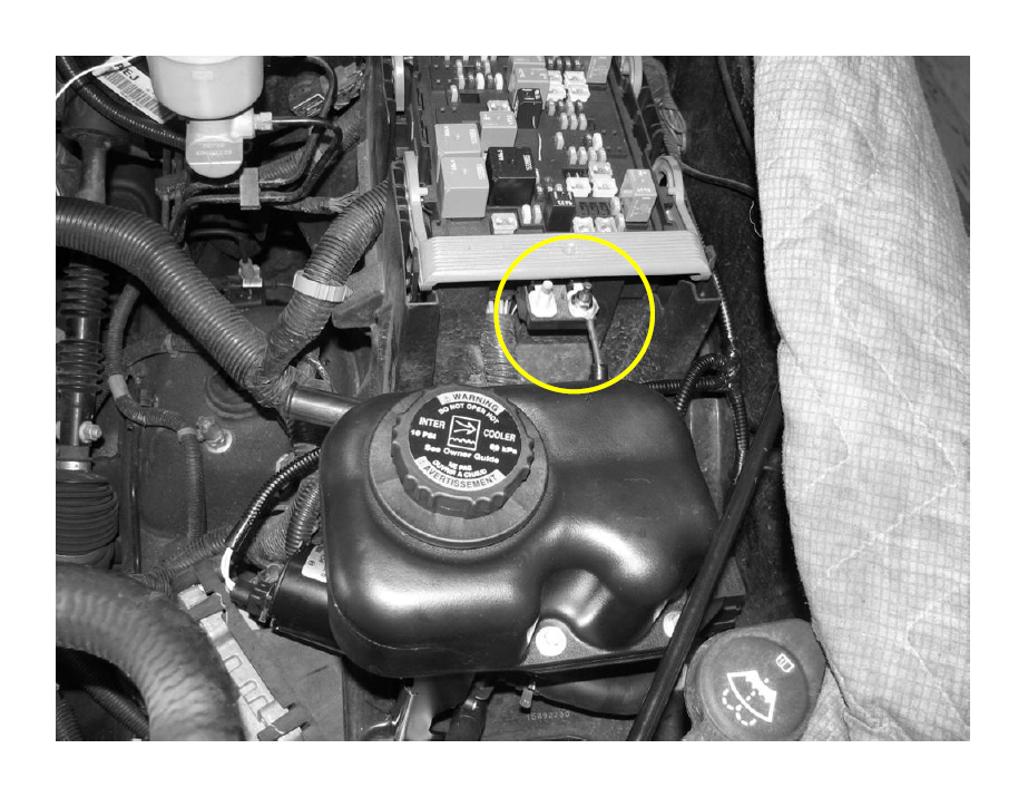
4. Solder the supplied 10 amp fuse link to single lead (with no eyelet) to an ignition-on signal wire in the fuse box.
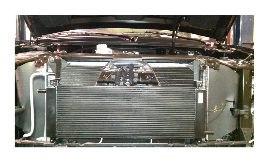
Intercooler Radiator Assembly Mounting
1. Remove the radiator trim cover by removing the pushpin retainers by pulling the center pin then lifting the cover up.
2. Remove the (4) M6 bolts holding the grille to the front structure. Using pliers, squeeze the retaining clips from the inside to remove the grill from the vehicle.
3. Remove the top (2) bolts securing the condenser in place and bolt holding the bottom of the power steering fluid cooler in place.
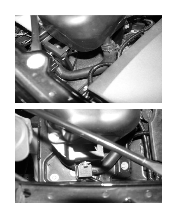
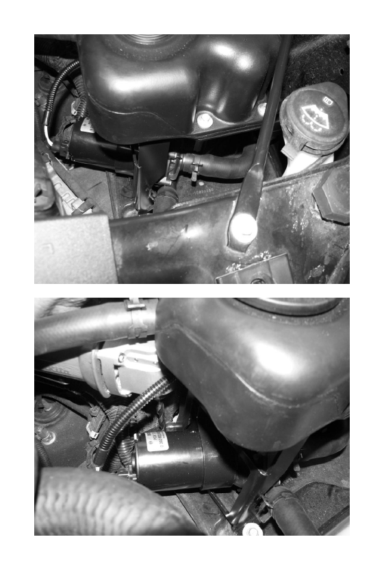
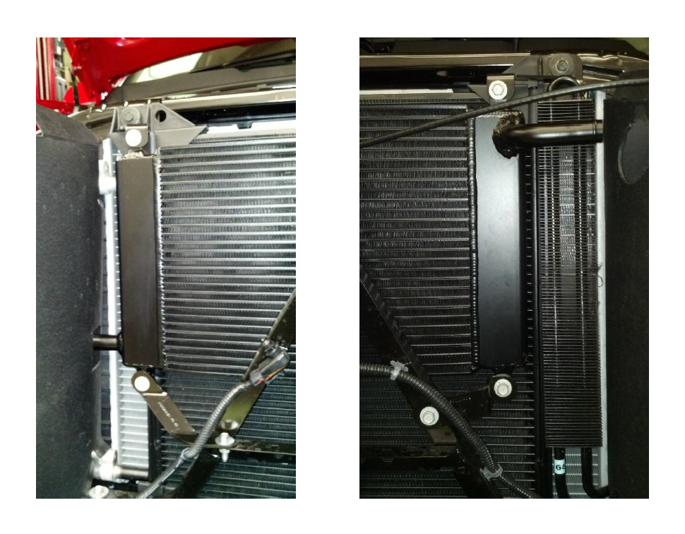
3. Pull the power steering fluid cooler forward. Slide the low temp radiator, from the driver side to the passenger side, in between the front structure and the condenser on PICKUP MODELS ONLY. FOR SUV MODELS THE LT Radiator IS TO MOUNT IN FRONT OF THE CONDENSER STRUCTURE. The orientation of the intercooler changes between models as well. See photos below. There are two separate sets of mounting tabs included in this kit. Be sure to use the kit specified for your vehicle. SUV or Pickup. See photos below of each for bracket orientation and LTR mounting.
SUV MODELS
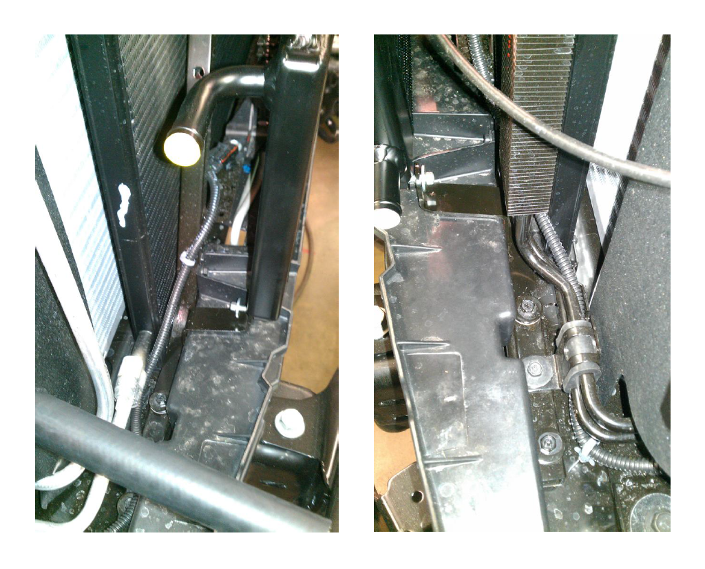
PICKUP TRUCK
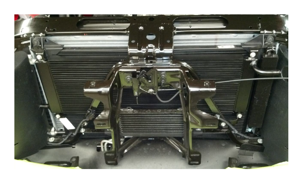
5. Mount the top of the Radiator using the brackets provided. Use (2) M6 x 1.0 x 18.5 bolts to fasten the brackets to the upper Radiator mounting tabs. Use the take off fasteners to secure the brackets to the front structure. Leave these fasteners loose.
6. Mount the bottom of the Radiator using the brackets provided. Use (2) M6 x 1.0 x 18.5 bolts to fasten the brackets to the lower Radiator mounting tabs. Use (1) M6 x 1.0 x 18.5 bolt and (1) M6 Nut to secure the lower passenger side bracket to the front structure. Use the take off fastener to secure the lower driver side bracket to the front structure.
7. Torque all bolts to 8 – 12 Nm.
8. Connect the Radiator Inlet (driver side) to the I/C Pump using the ¾” bulk hose that is 464mm long. Route the hose from the Radiator through the front structure to the pump. Secure the hose to the fittings using (2) constant tension clamps. Trim plastic as needed to route hoses through engine bay.
9. Connect the 1321mm bulk hose to the Radiator using (1) constant tension clamp and route the hose through the front structure and along the stock heater lines.
10. Inspect all installed coolant lines for any kinks.
Intake Manifold and SLP Charger
1 Remove Fuel Charging Assembly with Intercooler from packaging.
2 Attach the modified intake to cylinder head gaskets to the lower intake manifold.
3. Remove the tape from the cylinder heads. Carefully clean the cylinder head to intake manifold mating surfaces using brake clean or rubbing alcohol.
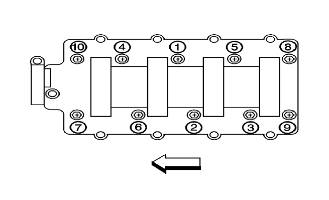
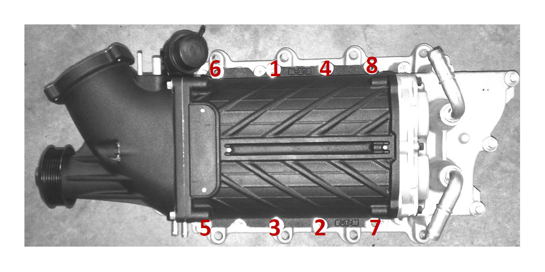
6. Carefully place the intake manifold assembly (with gaskets) down onto the cylinder heads. Be careful not to damage your sealing surfaces or gaskets during this step. Fasten the intake using (10) M6 x 1.0 x 74.5mm bolts. Torque to 8 – 12 Nm in the sequence shown.
5. Install the upper to supercharger gasket and the supercharger bypass gasket in the intake manifold assembly.
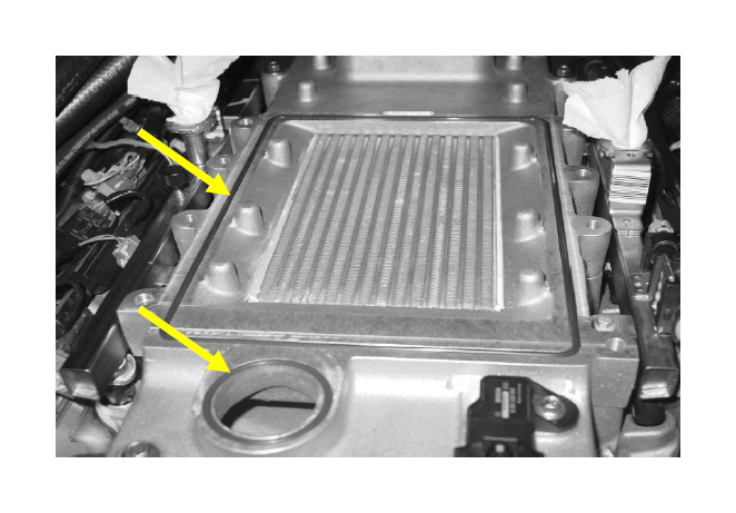
6. Connect the Radiator Outlet hose routed along the stock heater lines to the passenger side intercooler fitting using (1) constant tension clamp. Connect the reservoir bottle inlet hose routed along the main wiring harness to the driver side intercooler fitting using (1) constant tension clamp.
7. Route the B cable in between the water pump and the lower intake manifold and in between the alternator bracket and the lower intake manifold.
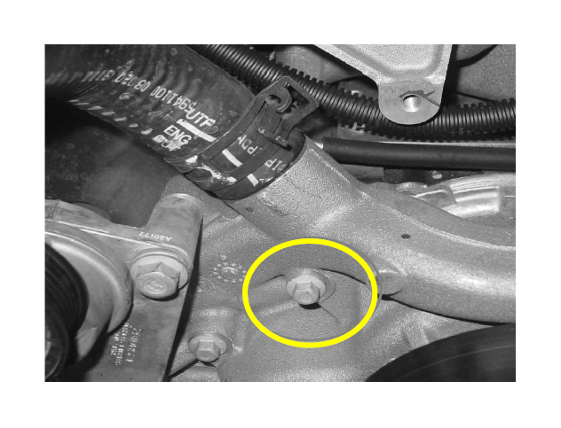
8. Remove the M8 bolt shown from the water pump.
9. Install the Front Belt Drive Bracket using (3) M8 x 1.25 x 123mm bolts. Torque to 24– 26 Nm. Fasten the idler to the bracket using (1) M8 x 1.25 x 28mm bolt. Torque to 24 – 26 Nm.
10. Remove the SLP Black Charger from the packaging. Install the “TVS 1900” and “SLP Supercharged” badges with the Allen head M4 black bolts provided. Next, install the unit using (8) M8 x 1.25 x 84mm bolts. Torque to 24 – 26 Nm in the sequence shown.
12. Route the TMAP harness between the coils and injectors on the driver side and connect TMAP.
13. Connect the VMV and all (8) injectors.
14. Run the PCV Purge tube from the lower port on the driver side of the supercharger to the rear of the driver side valve cover using (2) 3/8” constant tension clamps. Connect the supercharger bypass valve port to the port (smaller of the two ports) on the passenger side of the supercharger.
15. Using the modified VMV line, connect the 90deg fitting to the front of the VMV and connect the bulk hose to the upper port on the driver side of the supercharger using (1) 3/8” constant tension clamp. Connect the plastic VMV line to the rear of the VMV.
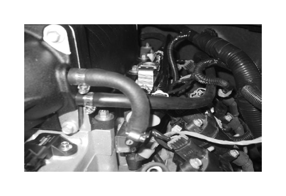
16. Connect the Brake Booster Hose to the fitting on the brake booster using the stock take off constant tension clamp. Route the hose around the back of the supercharger and secure it to the 5/8” fitting on the passenger side of the supercharger using (1) constant tension clamp.
17. Install the (2) take off throttle body studs in the (2) upper holes in the front inlet of the supercharger. Torque to 8 – 12 Nm. Install the stock throttle body gasket in the front inlet of the supercharger.
18. Using the rest of the take off hardware, fasten the throttle body to the supercharger. Torque to 8 – 12 Nm. Connect the wiring harness to the ETC connector.
19. Install the alternator in the stock location using the take off M8 fasteners. Torque to 24 – 26Nm.
20. Connect the B cable to the alternator using the take off M6 nut. Torque to 8 – 12Nm. Plug in the alternator harness into the top of the alternator.
21. Install the FEAD belt.
AIR BOX INSTALLATION
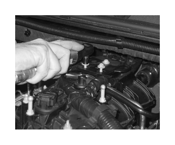
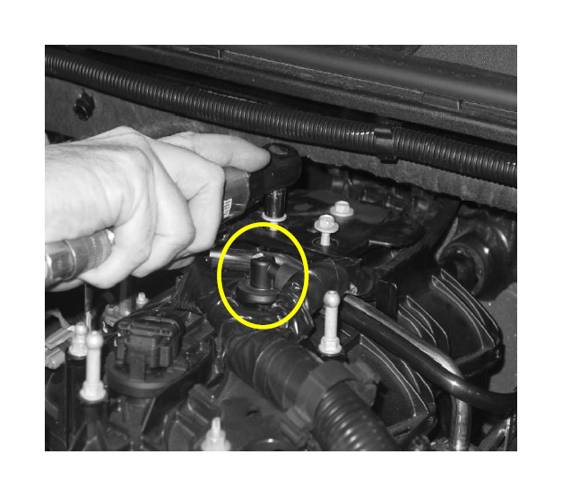
1. Remove the entire stock airbox as one piece. It is only held in by 3 rubber pins. Pull up and out with some force to remove the stock box from the truck.
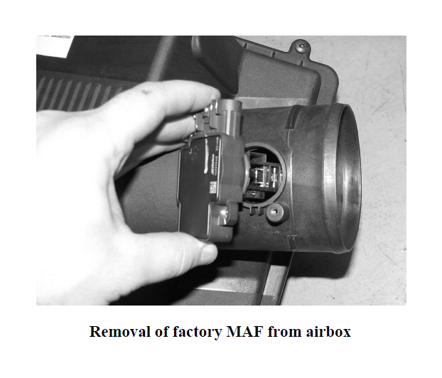
2. Unscrew the factory MAF sensor and remove it from the airbox (screw size is a standard T15 Torx). Set it aside in a safe place and be VERY CAREFUL removing as it is very delicate.
3. Next remove the four bolts in the black plate that was under the stock airbox, as well as the black plate.
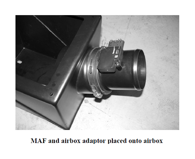
4. Next, insert the factory MAF sensor into the airbox MAF tubeincluded and thread in the factory screws.
5. Insert one of the two rubber inlet tube adaptors onto the airbox, and then proceed to insert the wider end of the airbox adaptor into the airbox. Make sure the airbox adaptor sits concentrically in the hole and the MAF is facing up. Proceed to tighten the worm drive clamp.
6. Next place SLP’s new cold air box in place with the large square opening in the box facing the fender.
7. Only three of the bolts will be reused to hold the SLP airbox in place. Tighten all three bolts to secure the box.
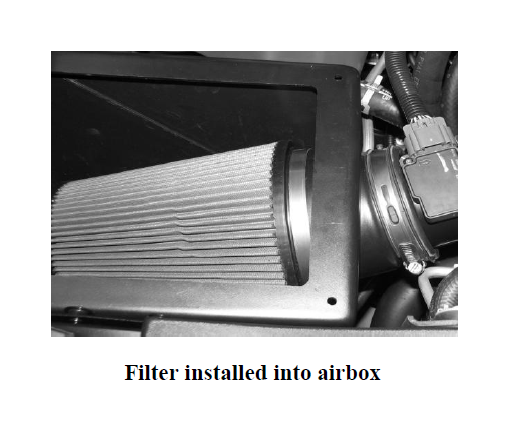
8. Next install the SLP high flow filter. The filter is a tight fit when installing it into the box, so the following steps must be taken to get the filter in the box with ease. First, position the filter so that the entire open end of the filter is under the mounting stub on the inside of the box. Push the filter down and in, under the stub. The filter will now be completely in the box under the mounting stub. Next, slide the filter to the fender side of the box so that the outlet of the filter can slide onto the mounting stub inside the box. Slide the filter all the way onto the stub and tighten the worm drive clamp.
9. Place the SLP cover onto the air filter housing and push the screw plugs into the housing. Insert and tighten the four plastic screws into the screw plugs to secure the lid to the air filter housing.
10. Next reconnect the stock MAF wire harness to the MAF.
11. FOLLOW INSTRUCTIONS included in the “INTUNE” Handheld Programmer before starting vehicle as engine damage will result and you WILL VOID your warranty.