FREE 1 to 3-Day Delivery on Orders $149+ Details
How to Install Rough Country 2 in. Front / 4 in. Rear Spindle Lowering Kit on your Sierra
Installation Time
3 hours
Tools Required
- 24mm Wrench
- 22mm Wrench
- 21mm Wrench
- 18mm Wrench
- 17mm Wrench
- 16mm Wrench
- 15mm Wrench
- 13mm Wrench
- 12mm Wrench
- 10mm Wrench
- 8mm Allen Wrench
- Drill Motor
- Drill Bit 11/32
- Drill Bit 15/32
- Vise Grips
- Die grinder
- Floor Jack

Shop Parts in this Guide
FRONT INSTALLATION INSTRUCTIONS
1. Lift the front of the vehicle using a jack and support the vehicle with jack stands, so that the front wheels are off the ground
2. Remove the front tires/wheels., using a 21mm deep well socket
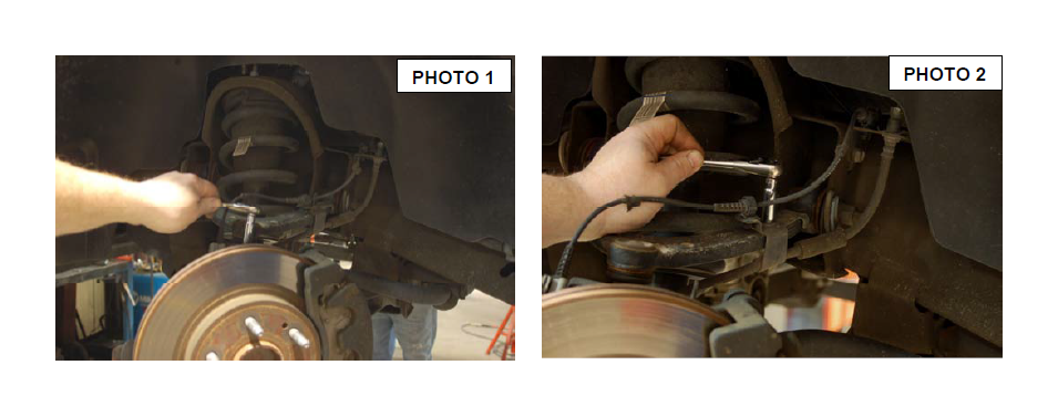
3. Starting on the driver side, remove the ABS sensor bracket from the top of the knuckle using a 10mm socket. See Photo 1. Next remove the ABS wire from the plastic clip. Remove the bracket from the control arm using a 10mm wrench. See Photo 2.
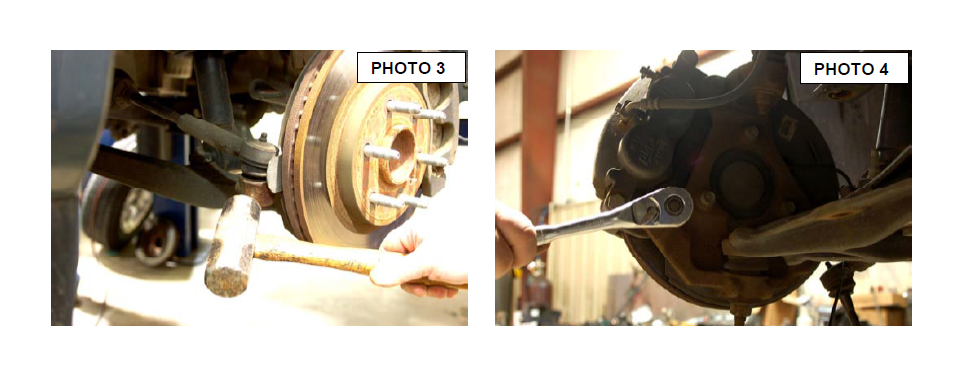
4. Using a 21mm wrench remove the tie-rod nut and strike the side of the mount to dislodge the taper lock on the tie-rod. See Photo 3.
5. Remove the brake caliper from the factory knuckle using a 18mm socket. See Photo 4. Hang or tie the caliper out of the way.
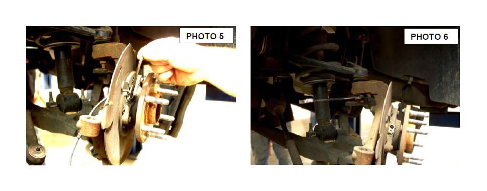
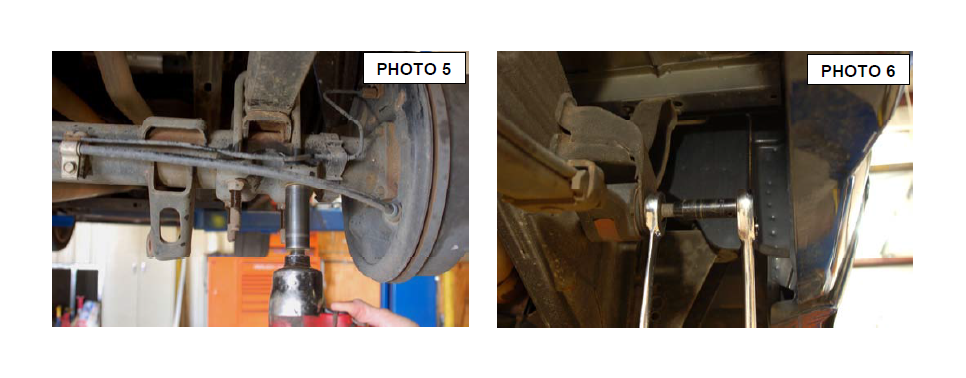
6. Remove the ABS sensor from the bearing assemble using a 8mm allen wrench. See Photo 5.
7. Remove the upper ball joint nut using a 18mm wrench, strike the knuckle on the side to dislodge the ball joint. See Photo 6.
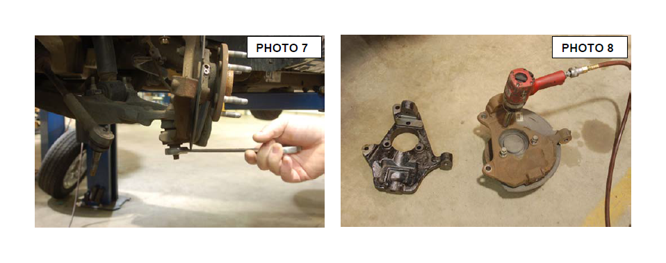
8. Remove the lower ball joint nut using a 24mm wrench, strike the side of the knuckle to dislodge the ball joint. See Photo 7. Remove the knuckle from the vehicle.
9. Remove the bearing assemble and dust shield from the stock knuckle using a 15mm socket. See Photo 8. Insert bearing assemble and dust shield in the new Rough Country lowering knuckle and tighten.
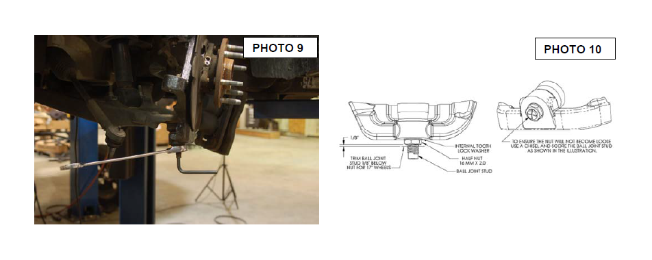
10. Install the knuckle on the lower ball. If using a 18” wheel or bigger use the factory hardware and tighten with a 24mm wrench. See Photo 9. Insert the upper ball joint into the knuckle with factory hardware tighten with a 18mm wrench.
11. **Note** If you using a 17” wheel with this lowering knuckle you will have to using the supplied 16mm nut and internal locking washer. Also the length of the ball stem will have to be cut off. Using a cut off blade cut the threaded stem off 1/8” below the nut. See Photo 10.
12. Insert the tie-rod end and tighten with a 21mm wrench and install the ABS sensor in the knuckle with a 8mm allen wrench.
13. Install the brake caliper with factory hardware and tighten with a 18mm socket.
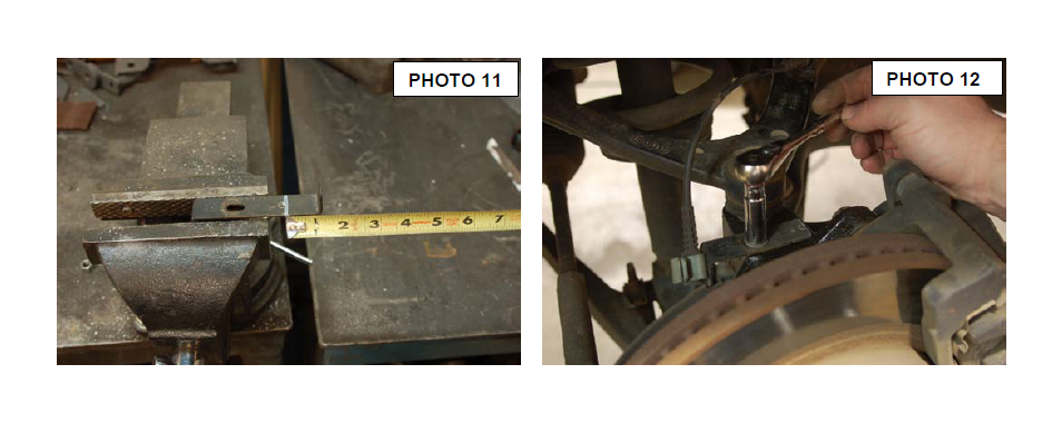
14. Place the ABS bracket in a vise and mark a line 1 1/8” from the end of the bracket. Cut the bracket so it fits on top of the new knuckle. See Photo 11.
15. Insert the ABS wire back onto the bracket and bolt the bracket to the new knuckle using factory hardware and a 10mm socket. See Photo 12. Repeat steps 2-13 on the passenger side.
16. Installing tires and wheels and set the truck on the ground.
REAR INSTALLATION INSTRUCTIONS
1. Lift the rear of the vehicle using a jack and support the vehicle with jack stands, so that the rear wheels are off the ground.
2. Remove the rear tires/wheels., using a 21mm deep well socket.
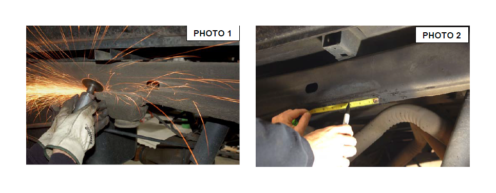
3. Remove bump stop. Using a cutoff wheel, cut all 4 sides of the bump stop and remove as shown in Photo 1.
4. Using the 2 existing “underneath” welds on the frame, measure to center and mark for new bump stop location. Photo 2.
5. Drill a 11/32” hole and install the stock bolt along with the factory bump stop.
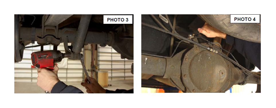
6. Using a 21mm socket and wrench, remove the shocks. Retain hardware for re-use with new provided RC shock. Photo 3.
7. Remove the bolt holding the brake line bracket to the rear-end. Photo 4.
8. Supporting rear axle, use a 21mm socket and remove the u-bolts on both driver and passenger side. Photo 5.
9. On the passengers side, using a 24mm wrench for nut and a 12mm for bolt on front 21mm for nut and 10mm for bolt on rear, remove the leaf spring bolts and remove from vehicle. See photo 6 *note* If equipped with tow hitch, this must be removed
10. Using same wrenches as passenger side leaf, remove the rear bolt in the frame mount and the shackle on the drivers side. Only loosen the front bolt only. Do not remove!
11. Carefully slide the rear end toward the passengers side keeping the axle firmly on the stands for support.
12. Swing the drivers side leaf out and under the axle.
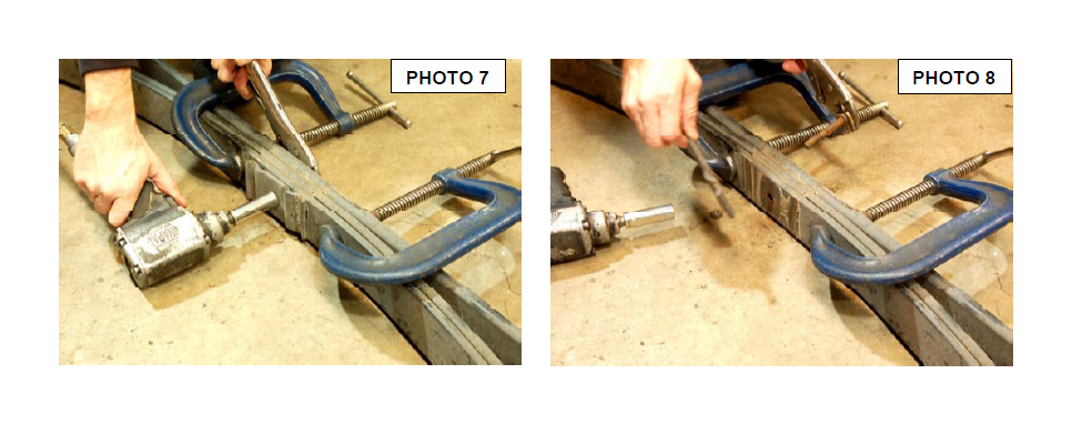
13. As shown in Photo 7, using a 15mm wrench and vise grips on the end of the pin, remove the ubolt plate and bolt.
14. After removing plate, flip bolt in insert on the opposite side as shown in Photo 8.
15. Using a 15mm and vise grips, re-tighten pin into the shown position in Photo 9.
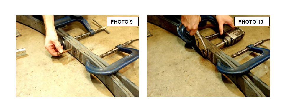
16. Install Socket Head Bolt and nut into the plate as shown in Photo 10. *note direction of plate when placing bolt*
17. Using a 9/16 wrench and 5/16 Allen wrench, tighten bolt in place. Photo 11
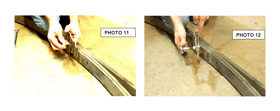
18. Using 21mm socket and wrench, remove the stock shackle and retain stock hardware. Photo 12
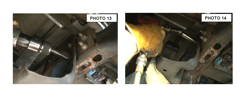
19. Using a die-grinder or air chisel remove the three factory rivets on the hanger bracket. See Photo 13.
20. Use a 15mm socket to remove the top rear bolt on the hanger bracket. See Photo 14.
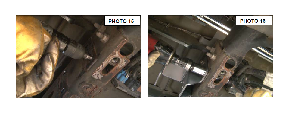
21. Drill out the three rivet holes to 15/32” (clearance for a 7/16” bolt). See Photo 15.
22. Install the new hanger bracket on the frame, insert the factory bolt in the top rear hole and hand tighten. Use the supplied 7/16” x 1 1/4” long bolts, washers, and nuts for the other three holes in the hanger bracket. Tighten 7/16” bolts with a 16mm and
17mm socket and wrench and the stock bolt with a 15mm socket. See Photo 16.
23. Reinstall the driver leaf spring using the stock bolts with axle on top side of leaf. You will need the 24mm wrench with the 12mm on end and the 21mm wrench with 10 mm on end. Tighten to correct torque spec.
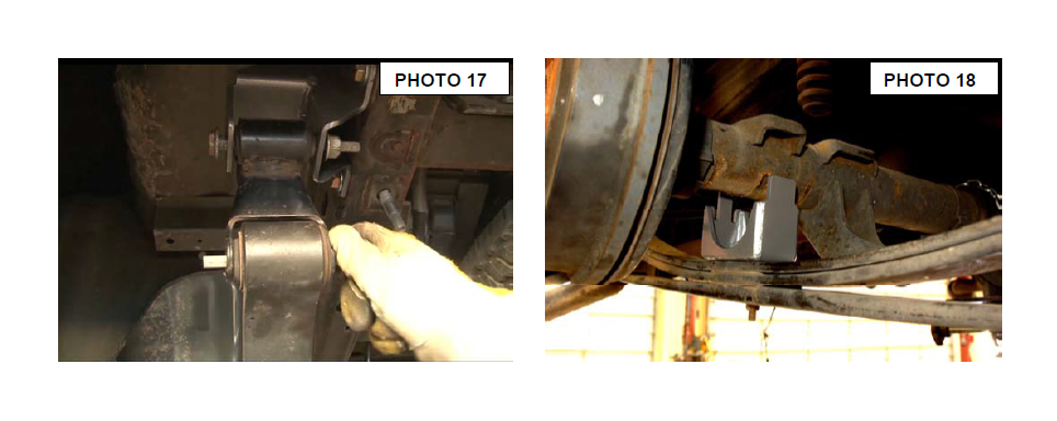
24. Install the factory shackle in the lower hole of the hanger bracket, using the stock hardware and previous wrenches used. See Photo 17. The lower hole is a 4” drop in the rear and the upper hole of the hanger bracket is a 4.5” drop.
25. On the drivers side frame, remove the e brake cable hanger using a 13mm socket.
26. Install the provided axle saddle with the spring hole positioned to the front of the truck .. See Photo 18.
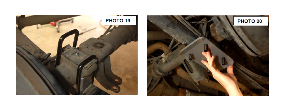
27. Place the u-bolt plate with bolt head side in axle as indicated in Photo 19.
28. Install the provided u-bolts and new bottom plate as shown in Photo 19 and Photo 20.
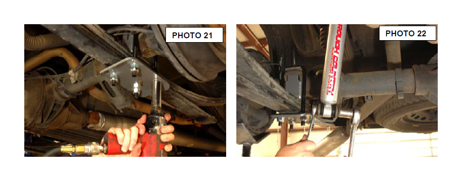
29. Using a 22 mm socket, install and tighten nuts to the u-bolt to correct torque. See Photo 21
30. Repeat steps 3-25 for passenger side.
31. Reinstall the brake line bracket to the axle using a 13mm wrench.
32. Reinstall the bolt in the e-brake hanger on the drivers side frame using a 13mm wrench.
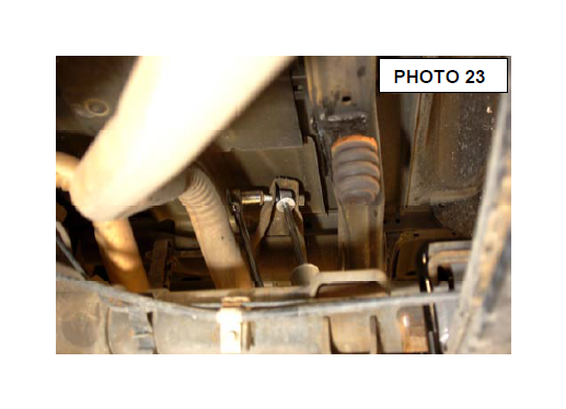
33. Install the new 2.0 shocks with existing hardware with a 21mm wrench and a 21mm socket. Photo 22 & 23.
34. If truck was equipped , reinstall the factory hitch.
35. Install the rear tires/wheels., using a 21mm deep well socket.
36. Remove all jack stands.
37. Lower vehicle and follow post installation instructions below.
POST INSTALLATION
1. Check all fasteners for proper torque. Check to ensure there is adequate clearance between all rotating, mobile, fixed and heated members. Check steering for interference and proper working order. Test brake system.
2. Perform steering sweep. The distance between the tire sidewall and the brake hose must be checked closely. Cycle the steering from full turn to full turn to check for clearance.
3. Re torque all fasteners after 500 miles. Visually inspect components and re torque fasteners during routine vehicle service.
4. Readjust headlights to proper settings and take truck in for a front-end alignment to a qualified alignment professional.