FREE 1 to 3-Day Delivery on Orders $149+ Details
How to Install Fabtech 6 in. Performance Lift System w/ Shocks on your Dodge Ram
Tools Required
- FLOOR JACK & JACK STANDS
- ASSORTED METRIC AND S.A.E SOCKETS & WRENCHES
- SPECIALTY PRODUCTS, #40940 (Bushing removal tool)
- TORQUE WRENCH
- DIE GRINDER WITH CUT OFF WHEEL AND GRINDING WHEEL
- LARGE DEAD BLOW HAMMER
- TORSION BAR REMOVAL TOOL
Parts List / Hardware
FRONT SUSPENSION INSTRUCTIONS:
1. Disconnect the negative terminal on the battery. With the vehicle on level ground set the emergency brake and block the rear tires. Measure the front ride height of the truck from hub center of the wheel to the top of the fender well. RECORD THIS MEASUREMENT BELOW FOR LATER USE.
Driver Frt. _____________ Passenger Frt. __________________
2. Jack up the front end of the truck and support the frame rails with jack stands. NEVER WORK UNDER AN UNSUPPORTED VEHICLE! Remove the front tires.
3. Locate the torsion bar adjusting cams and threaded bolts. Measure exposed threads of torsion bar adjusting bolts and record for reinstallation. IT IS IMPEARATIVE THAT THE TORSION BARS BE RESET AT THIS HEIGHT FOR PROPER CV SHAFT ANGLES. VEHICLE MIGHT INCURR VIBRATIONS AND CV AXLE FAILURE IF SET AT A HIGHER OR LOWER POSITION. Mark torsion bars indicating driver and passenger. Using a torsion bar removal tool unload the torsion bars and remove. Retain the hardware for reinstallation. NOTE- Do not attempt to unload or remove torsion bars without the proper torsion bar tool. TORSION BARS ARE UNDER EXTREME SPRING LOAD!
4. Remove the factory transfer case skid plate and discard.
5. Disconnect the front drive shaft from the differential and discard the hardware.
6. Remove the front shocks and discard. Save the lower shock hardware and discard the upper hardware.
7. Locate the sway bar end links and disconnect them from the lower control arms and the sway bar. Discard the end links and hardware. Remove the factory sway bar from the truck and save along with the frame mount hardware.
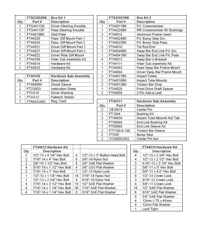
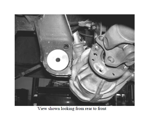
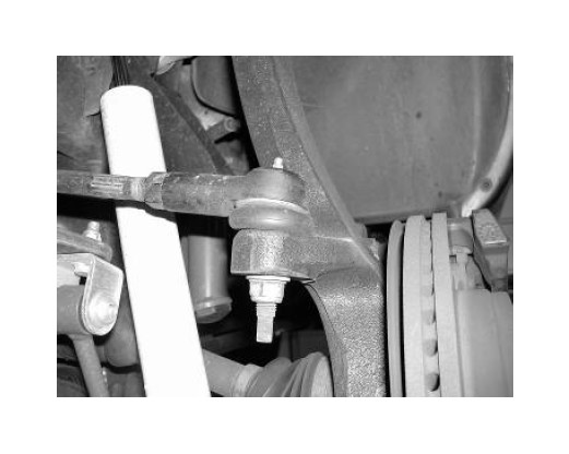
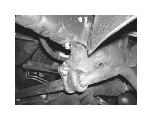
8. Working from the driver side of the vehicle, disconnect the tie rod ends from the steering knuckle by striking the knuckle to dislodge the tie rod end. Use care not to damage the tie rod end when removing. Discard the hardware as a new Fabtech tie rod end will be installed later. SEE PHOTO IN NEXT COLUMN.
9. Remove the brake caliper and place it next to the frame. Do not overstretch the brake hose when doing so. DO NOT LET THE BRAKE CALIPER HANG FROM THE BRAKE HOSE. Retain the hardware for reinstallation. Remove the brake rotor and save. Unplug the ABS wire at the plug behind the inner fender well and remove the ABS line clamp were it is attached to the spindle.
10. Remove the axle nut from the center of the hub and save.
11. Remove the upper and lower ball joint nuts and save. Using a large hammer strike the spindle to dislodge the ball joints from the spindle. USE CARE NOT TO DAMAGE THE THREADS ON THE BALL JOINTS. Remove the spindle from the truck.
12. Remove the bolts attaching the hub bearing to the spindle and save. Remove hub assembly along with the ABS sensor wire and dust shield from the spindle as one and save. NOTE; Do not disconnect the ABS sensor from the hub at anytime. Discard the spindle.
13. Remove the factory lower control arm bolts and save. Remove the lower control arm and save.
14. Remove the C.V. half shaft from the differential. This can be done by using a rubber mallet and striking the backside of the inner C.V. joint housing. Save the half shaft.
15. Repeat steps eight through fourteen on the passenger side of the truck.
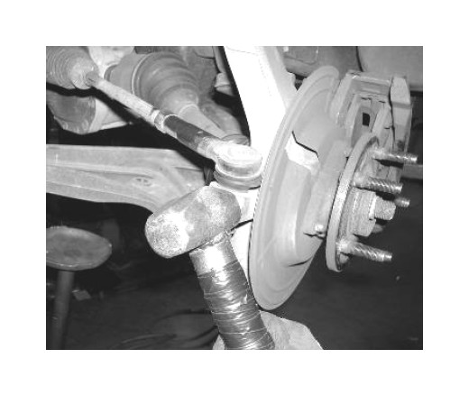
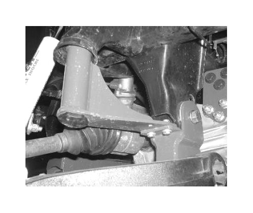
16. Remove the factory rear crossmember from the truck and discard the crossmember and hardware. SEE PHOTO ON NEXT PAGE.
17. Support the differential with a floor jack or transmission jack, remove the differential from the truck. Save the hardware from the driver rear differential mount and discard the rest.
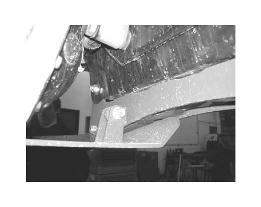
18. Locate the driver side rear lower control arm mount where the factory rear crossmember was previously removed. As shown in the picture below cut a 1” section from the frame. SEE PHOTOS BELOW AND IN NEXT COLUMN.
19. Locate the factory front lower control arm pockets. Grind 1/4” section from both pockets as shown in the photo. SEE PHOTO BELOW.
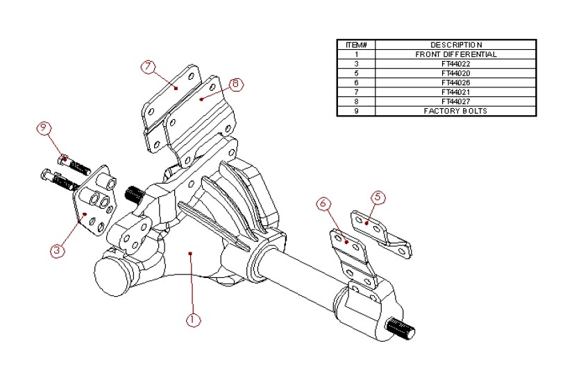
20. Locate FT44020 and FT44026 passenger side diff mounts. Using the supplied 1/2” X 2 3/4” hardware attach the brackets to the differential as shown in the diagram. Leave loose at this time. SEE THE DIAGRAM ON THE LAST PAGE.
21. Locate FT44021 and FT440027 Driver front diff mounts. Using the supplied 1/2”X 2 1/2” hardware attach the brackets to the differential as shown in the diagram. Leave loose at this time. SEE THE DIAGRAM ON THE LAST PAGE.
22. Locate FT44022 Driver rear diff mount. Using the original hardware attach the bracket to the original frame mount. Leave loose at this time. SEE THE DIAGRAM ON THE LAST PAGE.
23. Install the differential back into the truck attaching the new Fabtech drop brackets to the frame mounts. Use the supplied 1/2” x 2 3/4” bolts, nuts, and washer on the passenger side bracket, use the supplied 1/2” x 2 1/2” bolts, nuts, and washers on the driver side front bracket, and use the supplied 9/16” X 2 1/4” bolt, nuts, and washer on the driver rear brackets. Torque all differential hardware to 85 ft lbs.
24. Locate the factory rear lower control arm bushing in the frame. Use the specialty tool from Miller Tool Company, press each bushing out of the frame. Discard the bushing.
25. Locate the supplied FT44015 aluminum frame inserts. Install one into each factory rear lower control arm bushing holes. These can be installed into the frame using a large dead blow hammer. SEE PHOTOS BELOW.
26. Locate FT44011 front crossmember and install it into the front lower control arm pockets using the supplied 5/8” x 5” bolts, nuts, and washers. Leave loose at this time.
27. Locate FT44224BK rear crossmember and install it onto the new aluminum frame inserts previously installed using the 5/8” x 4 1/2” bolts, nuts, and washers. Leave loose at this time.
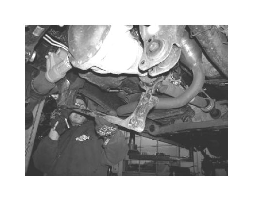
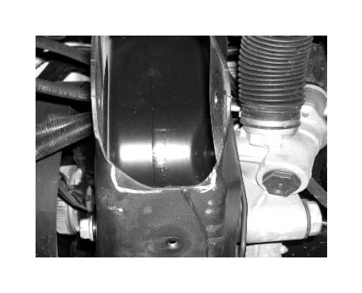
28. Locate the factory bump stop mount on the frame and remove the original bump stop. Using a die grinder with a grinding bit, open the hole on the top of the mount to 1 1/2” x 1 1/2” square. SEE PHOTO IN NEXT COLUMN.
29. Locate FT44024 (driver) front bump stop mount. Using the supplied 5/16” X 1 1/2” bolts, nuts, and washer attach the mount to the rear crossmember. Using the supplied 7/16” X 1” bolt and washer attach the upper part of the mount to the frame were the factory bump stop was previously mounted Torque the 7/16” bolt to 50 ft. lbs. and the 5/16” bolts to 18 ft. lbs. Install the supplied low profile bump stop to the bottom of the new mount. NOTE: On some models you will need to drill out the factory hole in the factory bump stop mount to 7/16”. SEE PHOTO BELOW.
30. Working from the driver side of the truck, install the factory lower control arm to the Fabtech crossmembers using the original hardware. The large factory Torx bolt goes into the rear lower control arm pivot. Leave loose at this time. 31. Install the C.V. half shaft back onto the differential by pushing the half shaft onto the splines until the snap ring locks.
32. Locate FT44115D (driver) Steering Knuckle. Attach the previously removed hub bearing to the knuckle in the same position as when removed using the original hardware and a small amount of the supplied thread locking compound on each bolt. Torque to 95 ft. lbs.
33. Attach the steering knuckle to the lower ball joint first, then slide the C.V. shaft end through the hub bearing, followed by the upper ball joint to the steering knuckle. Torque the lower ball joint nut to 85 ft lbs and the upper ball joint nut to 50 ft lbs. Using the original C.V. axle nut attach the C.V. axle to the hub assembly. Torque to 100 ft lbs.
34. Locate FT44019 skid plate and attach to the front crossmember using the supplied 1/2” X 2 3/4” bolt, nut, and washer, and to the rear crossmember using the supplied 1/2” X 1 1/4” bolt and washer. SEE PHOTO BELOW.
35. Torque the Fabtech crossmember bolts to 100 ft lbs and control arm pivot bolts to 110 ft. lbs.
36. Install the factory brake rotor and caliper. Use a small amount of the supplied thread lock compound on the caliper bolts and torque to 145 ft. lbs.
37. Locate FTS7159 front shocks (not included in the kit) and install onto the truck. Torque the upper mount to 20 ft lbs. and the lower mount to 35 ft lbs.
38. Using a measuring tape, measure the amount of threads showing from the tie rod end in. RECORD THIS MEASUREMENT. Loosen the jam nut holding the outer tie rod end on and remove the out tie rod end and discard. Leave the jam nut on the inner tie rod end.
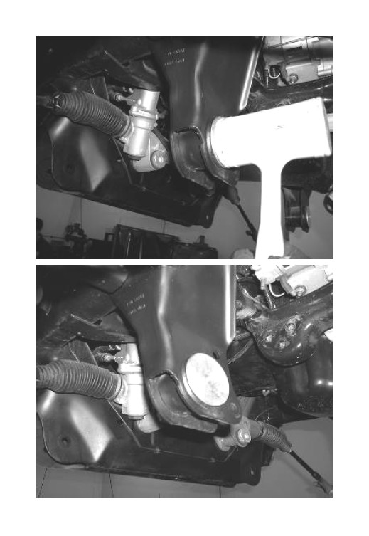
39. Locate FT44016 tie rod end and thread it onto the factory inner tie rod end to the measurement recorded earlier. Note: This is just a starting point, the toe adjustment will need to be set during the final alignment. Tighten the jam nut up to the tie rod end. Attach the tie rod end to the spindle using the supplied 14mm nut. Torque to 85 ft lbs. SEE PHOTO IN NEXT COLUMN.
40. Repeat steps thirty through thirty-nine on the passenger side of the truck.
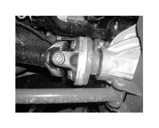
41. Locate FT44029 front drive shaft spacer. Using the supplied 12mm bolts, and washer attach the spacer and drive shaft to the front differential. Torque to 75 ft. lbs. SEE PHOTO BELOW.
42. Locate FT44044 (driver) FT44043 (pass) sway bar frame mounts. Attach the mounts to the frame using the original factory hardware. Leave loose. Attach the sway bar to the new brackets using the supplied 7/16” X 1 1/4” bolts, nuts, and washers. Torque all sway bar hardware to 55 ft. lbs. The sway bar should be offset forward a slight amount with the installation of the frame brackets. SEE PHOTO ON NEXT PAGE.
43. Locate FT44040 & FT44041 (driver & passenger) sway bar end links. Press one bushing and one sleeve into each end of the links.
44. Locate FT50013 sway bar u-brackets. Attach one to each end of the end links using the supplied 1/2” X 3” button head bolts, nuts, and washers. SEE DIAGRAM BELOW.
45. Using the supplied 3/8” nuts and washers attach the sway bar end links to the sway bar and the lower control arm. At times this may be easier to attach when the truck is completed and on the ground. SEE PHOTO BELOW
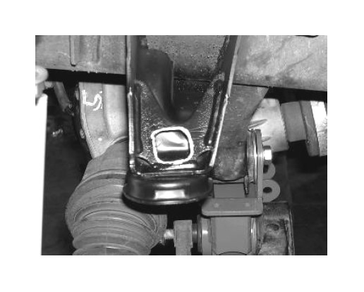
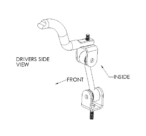
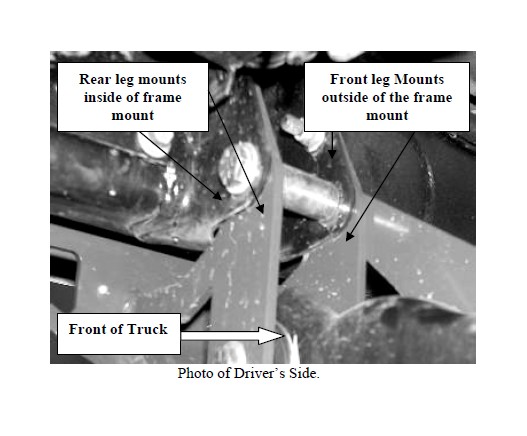
46. Locate FT44013 torsion bar drop bracket along with FT7100-6-100 frame sleeve. Locate the new drop bracket below the factory mount, aligning the new bracket against the frame (the Fabtech drop bracket mounts with the front leg of the bracket against the outside of the frame mount. The rear leg on the Fabtech bracket mounts on the inside of the frame bracket). Insert the sleeve into the factory bolt location as shown below. Use the supplied 1/2” X 4 1/4” bolt, nut, and washer on the factory frame mounts with the sleeve. Leave loose at this time. Repeat on the passenger side of the truck at this time. SEE PHOTO BELOW.
47. Using the supplied 7/16” X 4” bolts, nuts, and washers attach the factory crossmember to bracket mounts. Leave loose at this time. Using a drill with a 3/8” drill bit, drill the hole for the front mounting tab. Using the supplied 3/8” bolts, nuts, and washers attach it to the frame. Torque the 1/2” bolts to 80 ft. lbs, the 7/16” bolts to 60 ft. lbs, and the 3/8” bolts to 35 ft. lbs.
48. Locate the FT44017 impact strut tubes and install two bushings from the supplied bushing kit into each end of the tubes.
49. Using the supplied 7/16” x 3 1/2” bolts, nuts and washers attach the impact tubes to the rear crossmember tabs. Leave bolts loose at this time.
50. Attach FT44018 impact tube mounts to the free end of the impact tubes using the supplied 7/16” x 3 1/2” bolts, nuts, and hardware. Leave loose at this time.
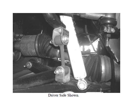
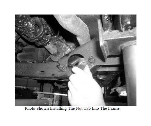
51. Swing the strut tube with the rear mount bracket attached up to meet the transmission crossmember. With a center punch mark the hole and drill out to 7/16”. Using the supplied 7/16” x 1 1/4” bolts and washers along with the supplied FT44034 nut tab attach the bracket to the frame. Torque the rear mount bracket to 50 ft lbs, and the 7/16” impact tube bolts to 45 ft lbs. SEE PHOTO BELOW.
52. Reinstall the driver and passenger side torsion bars into the truck and reset to the previous recorded measured height.
53. Install front tires and wheels. Torque lug nuts to wheel manufacturers specifications
Double Check That All Nuts And Bolts Are Now Tight Before Proceeding To The Rear.
REAR SUSPENSION INSTRUCTIONS:
54. Jack up the rear end of the vehicle and support the frame rails with jack stands. Block the front wheels so the truck will not roll. Release the parking brake at this time. While supporting the rear differential remove the rear shocks, u-bolts, and lower axle down. Save the u-bolts and hardware, discard the shocks. USE CARE NOT TO OVER EXTEND THE BRAKE LINES.
55. Separate the springs and install the provided FT44056 add a leaf with the new center bolt in a pyramid pattern smallest on the bottom graduating to the longest on top. The factory flat overload leaf should remain on the bottom of the pack. (Make sure that the Factory Locating Dowel Pin is aligned throughout the entire leaf pack when installing the new center pin) Clamp the spring and tighten the center bolt as not to leave a gap between the springs. Cut the thread of the bolt smooth with the nut. The nut should be on the top of the leaf spring pack.
56. Using the factory U-bolts, nuts, and washers align the axle and springs and torque the U-Bolts to 90lbs.
57. Install the new Fabtech shocks (not included with the kit) and Torque to 65 lbs using factory hardware on both upper and lower mounts.
58. Recheck all bolts for proper torque. Recheck the front and rear brake hoses and ABS lines for proper clearances.
59. Install tires and wheels and torque lug nuts to wheel manufacturers specifications. Turn front tires left to right and check for appropriate tire clearance. Note-Some oversized tires may require trimming of the bumper and valance.
60. Check the front-end alignment and set to the factory specifications.
61. Check front differential fluid level due to CV Shaft removal.
62. Adjust the front headlights to the proper angle.
RETORQUE ALL NUTS, BOLTS AND LUGS AFTER 50 MILES AND PERIODICALLY THEREAFTER.