FREE 1 to 3-Day Delivery on Orders $149+ Details
How to Install Amp Research PowerStep Running Boards on your Ram
Installation Time
1 hours
Tools Required
- Safety goggles
- Measuring tape
- Flat blade screwdriver
- Phillips head screwdriver
- Right angle drill
- 1/8” drill bit
- 13 mm socket
- Ratchet wrench and extension
- Soldering iron
- Wire crimpers
- Wire stripper / cutter
- Corrosion inhibiter
- 3/16” hex key wrench (allen wrench )
- 1/8” hex key wrench (allen wrench)
- 4 mm hex key wrench (allen wrench )
- Pop rivet tool
- Electrical tape

Shop Parts in this Guide
INSTALLATION GUIDE
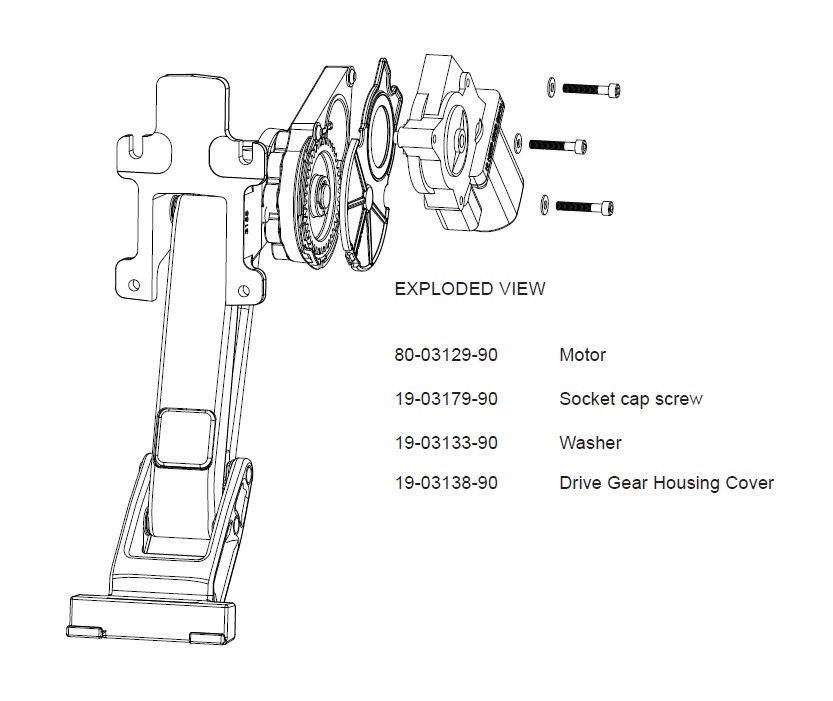
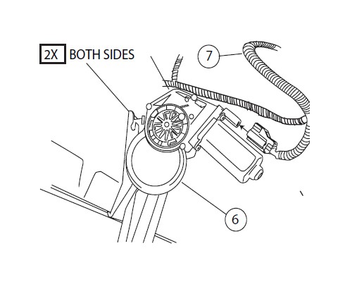
Attaching motor to linkage assembly
The motors need to be installed before continuing with the rest of the Power Step install.
CAUTION: HANDLE WITH CARE.
To ensure our customers receive all components with full integrity, we pack the motors separate from their linkage assemblies. This requires that the installer position and fasten the motor before continuing with the install. Please follow the instructions below and handle the assembly carefully.
CAUTION: Dropping the assembly or any excessive impact MAY cause damage to the motor.
Instructions:
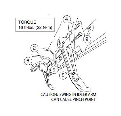
1. Position the gear cover in place as shown if not already in place.
2. Seat motor into position on the three mounting bosses. This may require an adjustment of the gear by moving the swing arms.
3. After seating into place, fasten the motor with the three motor mount screws with 4mm Hex Head. Tighten screws to 36 in-lbs (4N-m). Do not over torque.
Step 1.
Note: Steps 1-8 shown on driver side. Repeat these steps on passenger side.
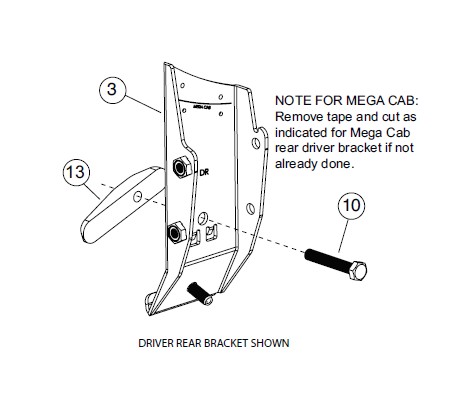
Counting large oval sill holes from the front, remove covering (plug or tape) from the below indicated mounting points.
QUAD CAB: 3rd and 7th from the front.
MEGA CAB: 3rd and 8th from the front.
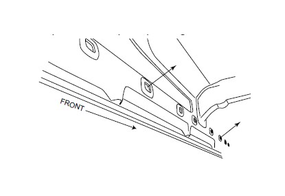
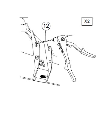
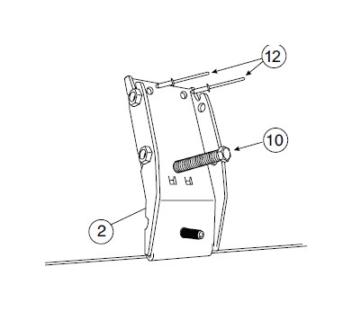
Step 2.
Prepare brackets for install
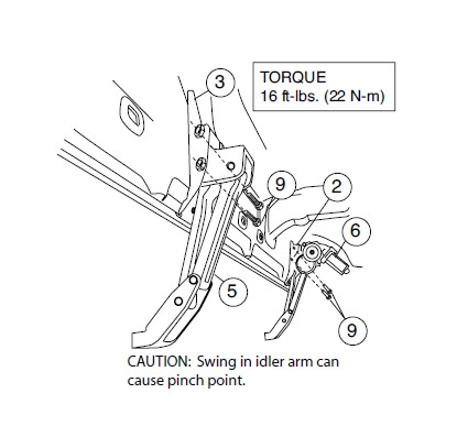
Step 3.
Install rear mounting bracket
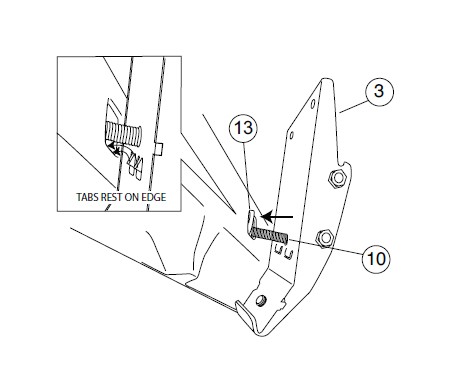
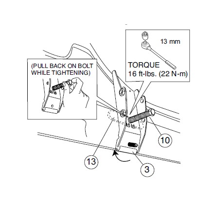
Step 4.
Fasten down rear mounting bracket
Step 5.
After drilling apply paint to prevent rusting.
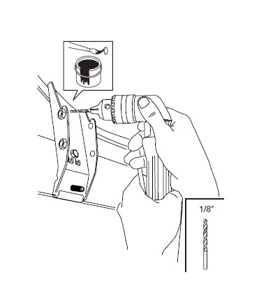
Step 6.
Bracket must be flush with the sidewall before riveting.
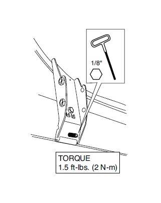
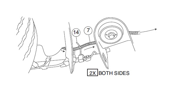
Step 7.
TORQUE 1.5 ft-lbs. (2 N-m)
Step 8.
Repeat steps 2 thru 6 for front mounting bracket.
Step 9.
DRIVER SIDE
Step 10.
PASSENGER SIDE
Install rear mounting bracket
Step 11.
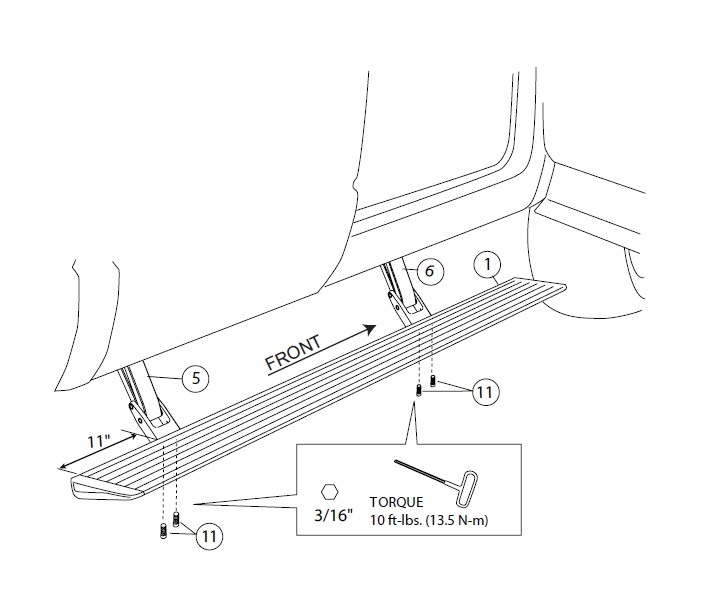
Mount step extrusion to linkage assemblies. Fasten loosely to allow for adjustments.
Step 12.
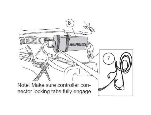
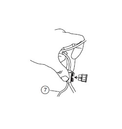
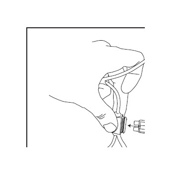
Attach 11” cable ties loosely around harness.
Attach wire harness to the control box. Slide controller through cable ties. Line up cable ties with grooves in controller and tighten.
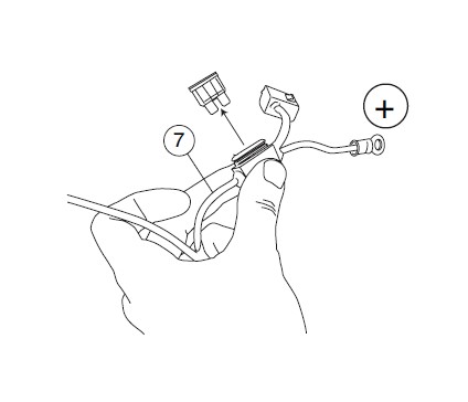
Step 13.
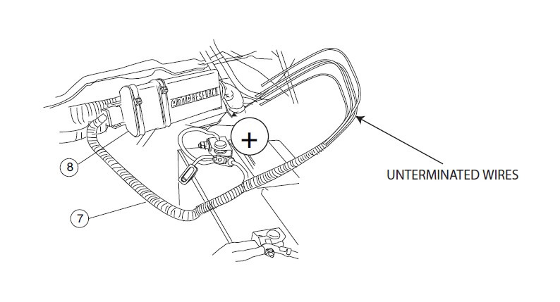
Remove fuse from Power Step wire harness.
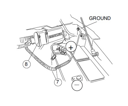
Step 14.
Attach power leads, red lead to positive battery terminal and the black lead to body ground as shown.
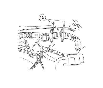
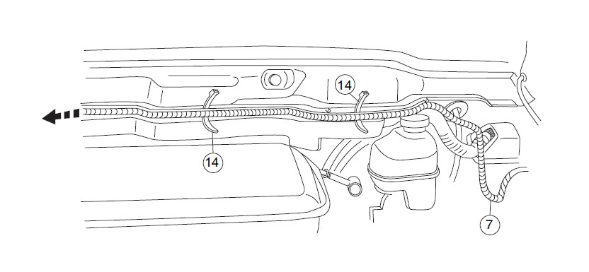
Step 15.
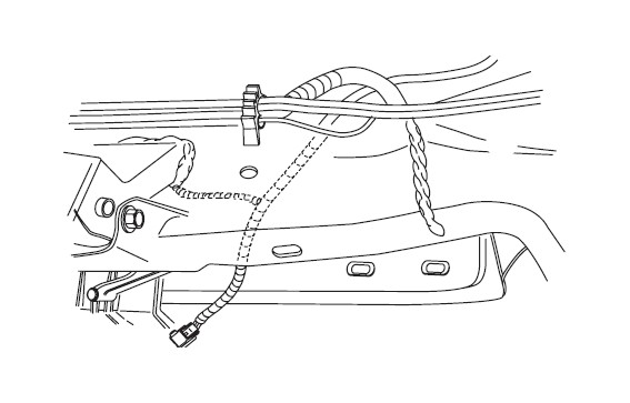
Route long leg of wire harness to passenger side across fire wall. Secure with tie wraps.
Step 16.
Step 17.
Step 18.
Step 19.
Step 20.
Step 21.
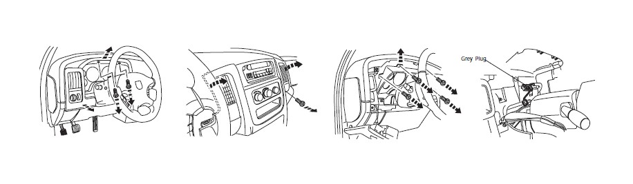
Remove plastic panel beneath steering column.
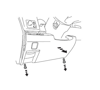
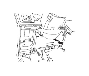
Step 22.
Remove metal panel revealed by step 21. Model years 2002-2005 will not have this panel to remove.
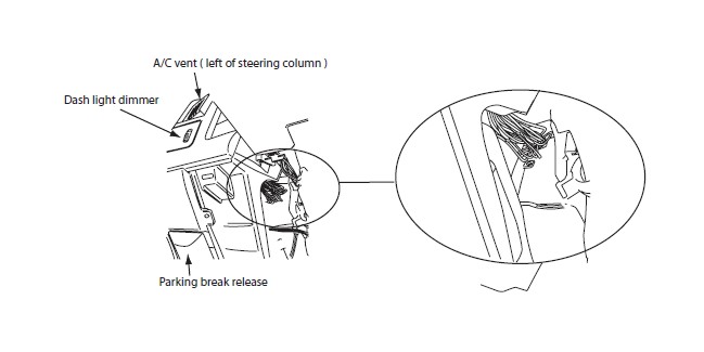
Step 23.
For 2006-2009 Models:
Locate bundle of wires high and to the left of diecast steering column mount.
Note: Bundle of wires leads toward back of fuel guage and is located directly above bundle of wires grounded to left panel.
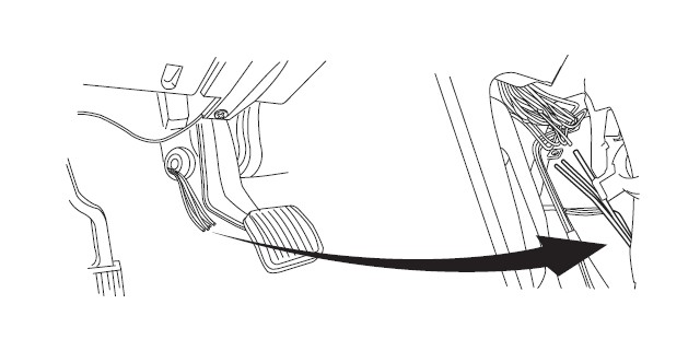
Step 24.
Pull wires through and run them up to the wires found in the previous step.
Step 25.
For 2002-2005 Models: Remove the cluster and instrument panel to access the grey plug.
Step 26.
Model Years 2004- 2009
Note: You may find two VL/YL wires in bundle. Only one works correctly.
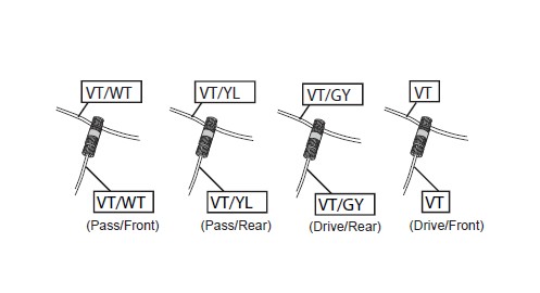
Step 27.
Model Years 2002- 2003
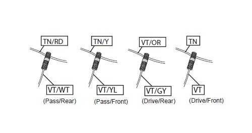
Step 28.
Step 29.
Using supplied Posi- TapsTM splice the Power Step trigger wires into their corresponding door ajar wire. See steps 26 and 27 for wire colors.
Step 30.
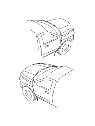
Step 31.
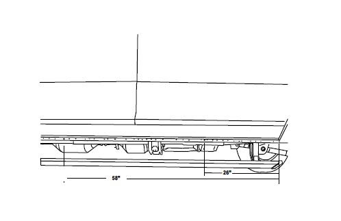
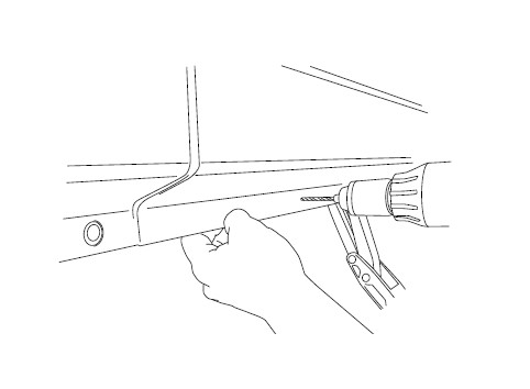
On each side of the vehicle measure from the front edge of door line on the pinch weld to the specified lengths below. Measure at 26” for the front LED Light and 58” for the rear LED Light.
Step 32.
Drill a 9/32” hole through the pinch weld at marked locations. Debur all holes.
Step 33.
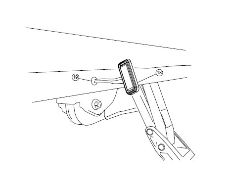
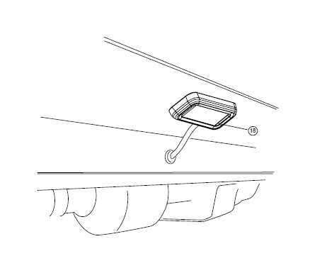
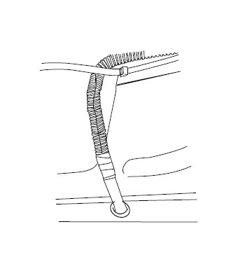
Insert grommet into drilled holes. Insert lamp wires through the grommets.
Step 34.
Affix lamp to rocker panel surface. Make sure lamp is affixed to a flat, clean surface.
Step 35.
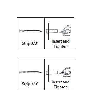
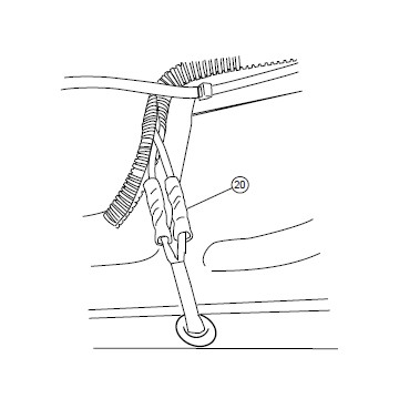
Using supplied butt connectors, connect the lamp wires. Red to Red, Black to Black. Once Crimped use heat gun to shrink tube.
Step 36.
Close and wrap with conduit and electrical tape. Secure all loose wires with cable ties, with lamp wires pulled upward to avoid any wire snagging.
Step 37.
Reinstall fuse.
Check that all doors activate the Power Step and the LED Lights work when doors open and close. Reinstall any remaining trim panels.
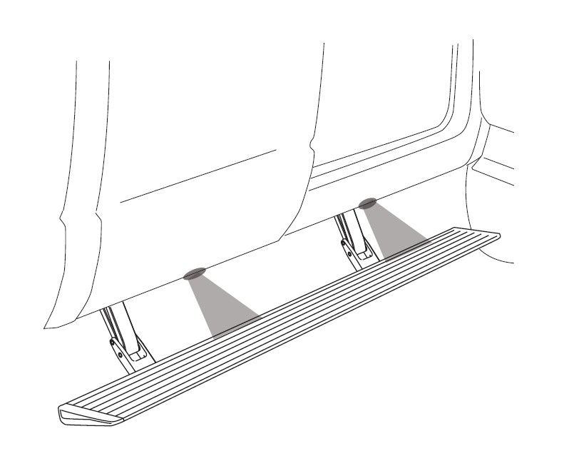
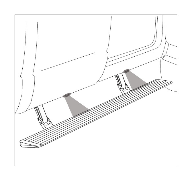
FINAL SYSTEM CHECK
Check that all doors activate the PowerStep and the LED lights work when doors open and close.
NORMAL OPERATION: When the doors open, PowerStep automatically deploys from under the vehicle. When the doors are closed, PowerStep will automatically return to the stowed/retracted position. Note that there is a 2-second delay before the PowerStep returns to the stowed/retracted position.
CORRECT OPERATION OF LIGHTS: All four lamps will illuminate upon opening any door of vehicle. Lamps will stay on until restowing of both Power Steps or until 5 minutes has expired with the doors open. When the lights timeout after 5 minutes, they can be reillumintated by closing and opening any door of vehicle.